Page is loading ...

MiniView™ Ultra 8 Port KVM Switch
User Manual (GCS138)

Welcome
For businesses that have grown faster than expected and four computers simply are no longer enough to meet constant needs, IOGEAR’s
eight-port MiniView™ Ultra is just the tool you need. The MiniView Ultra can reduce the need for redundant hardware monitors, mice and
keyboards. Now you can control all up to 512 computers with a single keyboard, monitor and mouse. The cumulative time, space and
financial savings can be considerable.
The MiniView™ Ultra is more than a simple eight-port KVM switch. Built-in AutoScan mode lets you conveniently monitor every attached
computer for a specified amount of time, while our On Screen Display technology allows you to assign a unique name to each computer
and access it via a slick, menu-driven interface. With its 1U, 19” rack-mountable casing and status-monitoring LEDs, the MiniView™ Ultra
is the perfect switch for your server room or any other multi-computer environment.
©2003 IOGEAR. All Rights Reserved. PKG-M0017
IOGEAR, the IOGEAR logo, MiniView, VSE are trademarks or registered trademarks of IOGEAR, Inc. Microsoft and Windows are registered trademarks of Microsoft Corpora-
tion. IBM is a registered trademark of International Business Machines, Inc. Macintosh, G3/G4 and iMac are registered trademarks of Apple Computer, Inc. IOGEAR makes no
warranty of any kind with regards to the information presented in this document. All information furnished here is for informational purposes only and is subject to change without
notice. IOGEAR, Inc. assumes no responsibility for any inaccuracies or errors that may appear in this document.

Package Contents & Requirements………………………....……...........................................................................................................
Features………………………………..……………………….................................................................................................…..............
Introduction ........................................................................................................................................................................................
Overview............................................................................................................................................................................................
Installation ………………………….…….........................................…..................................................................................................
Table of Contents
Powering Off ..…………..…........……..............................................................................................................................................…
Hot Plugging.......................................................................................................................................................................................
Port ID Numbering .………................................................................................................................................………....................…
Port Selection …...…...………..……….............................................................................................................................................…
OSD Operation ………………..………................................................................................................................................................
Function Keys …........………..……….............................................................................................................................................…
OSD Security …..……………..…….........................................................................................................................…....................…
PC Connection Table …..………….........................................................................................................................……..................…
Specifications …..….........................................................................................................................……..……..….........................…
Trouble Shooting.................................................................................................................................................................................
Technical Support .………………..………........................................................................................................................................…
Radio & TV Interference Statement.....................................................................................................................................................
Limited Warranty ........………………..……….......................................................................................................................................
02
03
04
05
07
14
15
16
17
18
20
25
26
27
28
29
30
30

2
Package Contents & Requirements
• 1 MiniView Ultra KVM switch
• 1 Power Adapter
• 1 Rack Mount Kit
• 1 Installation Manual
• 1 Quick Start Guide
• 1 Warranty Registration Card
Package Contents:
Note:
Please check to make sure that all components are included and
nothing is damaged. If you discover a problem, please contact your
dealer. Before connecting your MiniViewTM Ultra, read the manual
thoroughly and follow the installation and operation procedures
carefully in order to prevent any damage to the unit and/or any
devices it connects to.
System Requirements:
Computers with PS/2 or serial mouse* connection, PS/2 or AT
keyboard** connections, and HDDB15 VGA connection.
*Additional PS/2 to serial adapter required;
**Additional PS/2 to AT adapter required.
Optional Accessories:
G2L5002P – Bonded Microlite PS/2 KVM cable, 6’.
GUC100KM – PS/2 to USB adapter.
GCV160 – PS/2 to Mac ADB adapter

3
• Use one keyboard, monitor and mouse to control eight computers
• Control up to 512 computers by connecting multiple GCS138s together
• On Screen Display provides a convenient method for accessing the computers
• Add Macintosh support with IOGEAR’s optional Mac Adapter (GCV160)
• Connected computers can be added or removed from the setup without disturbing the other computers
• Keyboard/mouse translation allows PS/2 peripherals to control both PS/2 and serial-based computers
• Plug-n-Play monitor support. High-resolution video support (up to 1920 x 1440)
• No software required; built in AutoScan mode
• LEDs allow for easy status monitoring
• Lifetime technical support
• 3 Year Limited Warranty
Features

Introduction
The MiniView™ Ultra GCS138 is a KVM switch that controls access to multiple computers from a single console (keyboard, monitor, and mouse). Before the development of the
MiniView™ Ultra, the only way to control multiple computer configurations from a single console was through a complex and costly network system. Now, with the MiniView™
Ultra, you can easily access multiple computers in a simple and cost effective manner.
One MiniView™ Ultra can control up to eight PCs. Units can be cascaded to three levels, which means that as many as 73 MiniView™ units can control up to 512 PCs - all from
a single console.
Setup is fast and easy; just plug the cables into their appropriate ports. There is no software to configure so there is no need to get involved in complex installation routines or be
concerned with incompatibility problems. Since the MiniView™ Ultra accepts keyboard input directly, it works on virtually any hardware platform with all operating systems.
The MiniView™ Ultra provides three convenient methods to access any PC connected to the system: (1) using the port selection buttons on the front panel of each unit; (2)
entering HotKey combinations from the keyboard; and (3) selecting from on-screen menus through the On Screen Display (OSD) feature. In addition, a powerful Quick View Scan
feature allows you to auto scan and monitor the activities of all operating PCs on the installation one by one.
There is no better way to save time and money than with a MiniView™ Ultra. By allowing the MiniView™ Ultra to manage all the attached PCs, there is no need to purchase a
separate keyboard, monitor, and mouse for each PC, saving an enormous amount of space. It also eliminates the inconvenience and wasted effort involved in constantly moving
around from one PC to another.
4

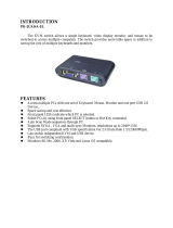
Overview
Front
5
1. Port LEDs
On Line: Lights ORANGE to indicate that the PC attached to the corresponding port is up and
running. If the LED is flashing, it indicates that the Port is being used for Cascading to another
MiniView
TM
ULTRA switch. Selected: Lights Green to indicate the current selected port. The
LED is steady under normal conditions, but flashes when its port is accessed under Auto
Scan mode.
2. Port Selection Switches
Press a switch to access the PC attached to the corresponding port. Pressing Buttons 1 and 2
simultaneously for 3 seconds performs a Keyboard and Mouse reset; pressing Buttons 7 and8
simultaneously starts Auto Scan Mode.
3. MiniView
TM
ULTRA Reset Switch
To reset the MiniView
TM
ULTRA, use a thin object (such as the end of a paper clip, or a ballpoint
pen), to press this recessed switch in to initiate a warm reset. If the switch is kept in for longer
than three seconds, a cold reset takes place.
4. Power LED
Lights to indicate that the MiniView
TM
ULTRA is receiving power.

Overview
Back
1. Port for optional power adapter
2. Console ports
3. CPU ports to connect computer, keyboard and mouse via our premium bonded KVM cables
4. VGA CPU ports to connect to your computer via our premium bonded KVM cables
6

Installation
Console Connection (power adapter connection)
To connect your console to the MiniView™ Ultra,
you will need your VGA monitor, PS/2 mouse, PS/2 keyboard
and the MiniView™ Ultra power adapter.
Attach the power adapter to your MiniView™ Ultra and plug
the other end of the adapter into a standard surge protector.
7

Installation
8
Console Connection (console ports on GCS138)
Step 1.
Connect your monitor cable into the console side of the MiniView™ Ultra video port.
Step 2.
Plug your PS/2 mouse and PS/2 keyboard into their designated ports on the console
side of the MiniView™ Ultra.

Installation
9
Step 1.
Connect the female VGA end of your IOGEAR KVM cable into the
male video port on the MiniViewTM Ultra labeled with a CPU port
number.
Step 2.
Plug in the PS/2 mouse and PS/2 keyboard connectors located on
the same end as the female video connector. The cables have
images on them indicating that they are for the keyboard or mouse.
CPU Port Connection

NOTE:
You may need to attach a PS/2 to AT adapter on the keyboard cable if your computer has an AT keyboard
connection. Also, if you do not have a PS/2 mouse port you will need to use our PS/2 to Serial adapter to
connect the mouse cable. You can use any manufacturer’s PS/2 to AT adapter but you must use our PS/2
to Serial adapters for the mouse.
Installation
10
Connecting the Computer (ports on the back of the computer)
Step 3.
Plug in the remaining PS/2 mouse and PS/2 keyboard connectors
into your computer’s keyboard and mouse ports.
Step 4.
Repeat steps 1-3 for any additional computers you wish to connect

Installation
11
Step 2.
Plug in the PS/2 mouse and PS/2 keyboard connectors located
on the same end as the female video connector. The cables
have images on them indicating that they are for the keyboard
or mouse.
Cascading MiniView™ Ultra units
Use standard IOGEAR PS/2 KVM cables to cascade units.
Step 1.
Connect the female VGA end of your IOGEAR KVM cable into the male video port on
an available CPU port of the MiniView™ Ultra.

Cascading MiniView™ Ultra units (continued)
Step 3.
Now, plug the male end of the video cable into the female video
port on the secondary MiniView™ Ultra’s console port.
Installation
12
Step 4.
Plug in the remaining PS/2 mouse and PS/2 keyboard connectors
into the keyboard and mouse ports on the secondary MiniView™
Ultra’s console port.

Congratulations! You have now completed the installation!
( ) connection indicate level 1 (8 computers)
( ) connection indicate level 2 (64 computers)
( ) connection indicate level 3 (512 computers)
(Max: 512 computers)
Cascading in Pyramid Format
Installation
13
Root/Slave Switch
Cascading units works in a pyramid format. The root unit is the first unit (top of pyramid) and the cascaded MiniView™ Ultras are the
secondary slave units. Only the first unit will be set to root while the preceding switches will be set to slave mode. There is a maximum of
three levels of MiniView™ Ultra for a maximum of 512 PCs.
.......
------

Powering Off
14
Powering Off and Restarting
If it becomes necessary to power off one of the MiniView™ units, you must do the
following before restarting it.
1. Shut down all the computers that are attached to it, as well as all the stations and all
the computers that are daisy chained down from it (all the child stations and the
computers attached to them).
NOTE: (1) If the unit is operating under Bus Power (without the optional Power Adapter),
you must unplug the power cords of any PCs that are connected to it that
have the Keyboard ‘Power On’ function, otherwise the switch will still receive
power from the PC.
(2) If the unit is operating under external power, unplug the power adapter cable.
(3) It is not necessary to shut down and restart any of the stations or computers
above the station you powered off.
3. After the MiniViews are up, Power On the PCs, starting with the ones attached to
the last station in the chain and working back to the station you originally shut down.
2. Wait 10 seconds, then power on the MiniView™ GCS138 stations starting with the
last station in the chain and working back to the station you originally shut down.

Hot Plugging
13
15
Hot Plugging
The MiniView™ Ultra supports hot plugging, which means that components can be
removed and added back into the installation by unplugging their cables from the CPU
ports without shutting the unit down. There are certain procedures that must be followed
in order for hot plugging to work properly:
• Hot Plugging CPU Ports:
1. The cable must be plugged back into the same port from which it was removed.
2. The mouse cable must be plugged in before the keyboard cable.
3. After plugging the cable back in, you must perform a KVM Reset on the First Stage
unit (by pressing the Reset switch).
• Hot Plugging Console Ports:
1. You may unplug the mouse and plug it back in again (to reset the mouse, for
example), as long as you use the same mouse.
2. If you plug in a different mouse, all the stations and all the computers on the
installation must be shut down for 10 seconds, then restarted.
Note: All MiniView™ units must be plugged in and receiving power prior to turning on
the power to the PCs. Press Port Selection Buttons 1 and 2 on the Level 1 unit
simultaneously for three seconds to perform a keyboard and mouse reset, if
necessary.

Port ID Numbering
16
Since each CPU Port on a MiniView installation is assigned a unique Port ID, you can
directly access any computer on any level. Specify the Port ID using the Hotkey port
selection method or the On Screen Display menu.
The Port ID is a one, two, or three digit number that is determined by the Stage Level
and CPU Port number of the MiniView unit that the computer is connected to. The first
digit represents the CPU Port number of the First Stage unit; the second digit
represents the CPU Port number of the Second Stage; the third digit represents the
CPU Port number of the Third Stage.
For example, a computer attached to a First Stage unit has a one digit Port ID Number
(1 - 8), that corresponds to the CPU Port number to which the computer is connected.
A computer attached to a Second Stage unit has a two digit Port ID number. The first
digit represents the CPU Port number (1 - 8), on the First Stage unit that the Second
Stage unit is cascaded down from; the second digit represents the CPU Port number
on the Second Stage unit that the computer is connected to. For example, a Port ID of
23 refers to a computer that is connected to CPU Port 3 of a Second Stage unit that,
in turn, is cascaded down from CPU Port 2 of the First Stage unit.

1. To access a computer attached to Port 3 of a Single Stage installation, key in 3 for
the Port ID, as follows:
[Ctrl], [Alt], [Shift], [3], [Enter]
2. To access a computer attached to Port 3 of a Second Stage unit that is cascaded
down from Port 2 of the First Stage unit, key in 23 for the Port ID, as follows:
[Ctrl], [Alt], [Shift], [2], [3], [Enter]
Note: You must key in the numbers one at a time.
3. To access a computer attached to Port 1 of a Third Stage unit that is cascaded
down from Port 4 of a Second Stage unit, which, in turn, is cascaded down from
CPU Port 2 of the First Stage unit key in 241 for the Port ID, as follows:
[Ctrl], [Alt], [Shift], [2], [4], [1], [Enter]
Port Selection
Port Selection
Controlling all the PCs connected up in your MiniView Ultra GCS138 installation from a
single console is simple. Four methods are available that provide instant access to any
PC on the chain: Manual, Quick View Scanning, HotKey, and OSD.
Quick View Scanning
Press Port Selection buttons 7 and 8 simultaneously for three
seconds to start the Quick View mode. This will cycle through the
ports one at a time. Press the [Space Bar] or a port key to stop it.
(See F2, p. 21)
Manual
Simply press the appropriate port selection switch on the MiniView
Ultra’s front panel. After you press the switch, the Selected LED lights
to indicate that the port is currently selected. The On Screen Display
automatically switches to highlight the PC that you have selected.
Note: On a daisy chained installation, you must press the Port
Selection switch on the MiniView Ultra Station that
connects directly to the PC you want to access.
HotKey
HotKey navigation allows you to conveniently access connected PCs directly
from the keyboard, instead of having to manually select them by pressing Port
Selection switches. To select a port with the HotKey method, do the following:
Note: After invoking the HotKey function with the [Ctrl+Alt+Shift] combination, you
must key in the Port ID and press [Enter] within one second for each keypress.
17

OSD Operation
18
OSD Operation
On Screen Display (OSD), provides a menu driven interface to handle the computer
switching procedure. Although HotKey switching still works, using OSD is a great deal
more convenient - especially in large, daisy chained installations where a great number
of computers are connected to several MiniView™ Ultra GCS138 units, and it is
difficult to keep track of which port a particular PC is attached to.
All operations start from the OSD Main Menu. To activate the Main Menu, press the
Control key twice ([Ctrl] [Ctrl]):
Note: You can use either the left or right Ctrl keys, but they must both be on the same
side (both left, or both right).
OSD always starts in List view, with the highlight bar at the same position it was in the
last time it was closed.
Note: You can optionally change the OSD HotKey to the Scroll Lock key
(see F6, p. 21), in which case you would press [Scroll Lock] [Scroll Lock].
• To activate a port, move the Highlight Bar to it then press [Enter].
• [Esc] cancels the current selection, or dismisses the current menu and moves back
to the menu one level above. If you are at the highest menu level, it deactivates OSD.
After executing any action by pressing [Enter], you automatically go back to the menu
one level above. Use the Up and Down Arrow Keys to move up or down through the
list one line at a time
• Use [Pg Up] and [Pg Dn] to move up or down through the list one screen at a time
/