Page is loading ...

MiniView
®
Ultra+
8-Port Multi Platform KVM Switch
User Manual (GCS1758)


Welcome
Thank you for purchasing the Miniview
®
Ultra+ KVM switch, one of the most versatile KVM switches
on the market. The New Miniview
®
Ultra+ is much more than a simple eight-port KVM switch. The dual
interface support allows you to connect both PS/2 and USB computers on the same switch. The multi-
platform support allows you to control Windows-based computers, Sun Solaris systems, Linux, or
even Macs by a single KVM switch. IOGEAR extended the multi-platform support by supporting the
special keys on both Sun and Mac keyboards.
©2004 IOGEAR. All Rights Reserved. PKG-M0114
IOGEAR, the IOGEAR logo, MiniView
®
, VSE are trademarks or registered trademarks of IOGEAR, Inc. Microsoft and Windows
are registered trademarks of Microsoft Corporation. IBM is a registered trademark of International Business Machines, Inc.
Macintosh, G3/G4 and iMac are registered trademarks of Apple Computer, Inc. IOGEAR makes no warranty of any kind with
regards to the information presented in this document. All information furnished here is for informational purposes only and is
subject to change without notice. IOGEAR, Inc. assumes no responsibility for any inaccuracies or errors that may appear in this
document.

Package Content
Overview
Features
System Requirements
Introduction
Installation
Operation
Hotkey Port Control
Alternate Hotkey Invocation Key
Keyboard Emulation
OSD Operation
Firmware Update Utility
Appendix
Troubleshooting
Specification
Technical Support
Radio and TV Interference Statement
Limited Warranty
2
3
4
5
6
10
15
20
24
25
27
38
45
46
47
48
49
50
Table of Contents

2
This package consists of:
1 Miniview
®
Ultra+ KVM
1 Firmware Upgrade Cable
1 Power Adapter
1 Rack Mount Kit
1 User Manual
1 Quick Start Guide
1 Warranty / Registration Card
Check to make sure that all the components are present and that nothing was damaged in shipping. If you
encounter a problem, please contact your dealer.
Package Contents

IOGEAR’s new eight-port Miniview
®
Ultra+ KVM switch is the ideal tool to help reduce redundant hardware.
Eight monitors, mice and keyboards are simply too expensive, bulky and inconvenient for most system
administrators. Why bother when you can control all eight, or even up to 512 computers with a single
keyboard, monitor and mouse? The added audio support allows you to enjoy music while working. Just think
of the time, space and money you’ll save, and added fun.
The New Miniview
®
Ultra+ is much more than a simple eight-port KVM switch. The dual interface support
allows you to connect both PS/2 and USB computers on the same switch. The multi-platform support allows
you to control Windows-based computers, Sun Solaris systems, Linux, or even Macs by a single KVM
switch. IOGEAR extended the multi-platform support by supporting the special keys on both Sun and Mac
keyboards. This KVM switch also comes with the IOGEAR VSE technology, which provides excellent video
resolution - up to 2048 x 1536. Built-in AutoScan mode lets you conveniently monitor every attached
computer for a specified amount of time, while our On Screen Display (OSD) technology allows you to assign
a unique name to each computer and access it via a smooth menu-driven interface. With its 1U, 19” rack-
mountable casing and status-monitoring LEDs, the Miniview
®
Ultra+ is the perfect switch for your server
room or any other multi-computer environment.
Overview
3

Features
• Dual interface support – supports computers with either PS/2 or USB Keyboard and mouse.
• Multi platform support – Windows, Mac, and Sun Solaris
• Easy to install – just plug the cables in
• Audio support allows sharing multimedia speakers and microphone
• Easy to operate – computer selection via front panel switches, intuitive OSD (on screen display), and Hot
Keys
• Security – 2 level password protection for OSD
• Hot Pluggable – both console side and computer side are hot swappable and auto-detect device changes
• LED Display for easy status monitoring
• Auto Scan Mode for monitoring all computers
• Complete keyboard emulation for error free booting
• Superior video quality; 2048 x 1536; support DDC2B.
• Total capacity expandable to support 512 computers via 3 levels of cascading
• Supports special keys on Sun and Mac keyboards
• Firmware upgradeable through flash ROM
• Designed for both desktop and rack mount
4

System Requirements
Console:
VGA, SVGA, or Multisync monitor capable of the highest resolution that you will be using on any computer in
the installation
USB mouse
USB keyboard
Computers:
VGA, SVGA or Multisync card;
Either a Type-A USB port, or PS/2 mouse and keyboard ports.
Cables:
For PS/2 computers, use IOGEAR part number G2L530XP*;
For USB computers, use IOGEAR part number G2L530XU*.
*”X” stands for the length of the cable: “1” is 3', “2” is 6', “3” is 10'.)
5

43
2
1
Introduction
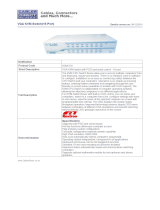
1. Port Selection Switches – Press a switch to access the computer attached to its corresponding port.
Pressing Buttons 1 and 2 simultaneously for 2 seconds performs a keyboard and mouse reset. Pressing
Buttons 7 and 8 simultaneously for 2 seconds starts
Auto Scan Mode
.
6
Front View

Introduciton
7
2. Port LEDs – The Port LEDs are built into the Port Selection Switches. The upper ones are the On Line
LEDs; the lower ones are the Selected Port LEDs.
The
On Line
LEDs light ORANGE to indicate that the computer attached to the corresponding port is up
and running. If the LED is flashing, it indicates that the port is being used for cascading to another
MiniView
®
Ultra+ (see
Two Stage Installation
, p. 12).
The
Selected
LEDs light GREEN to indicate that the computer attached to the corresponding port is the
one that has the KVM focus. The LED is steady under normal conditions, but flashes when its port is
accessed under
Auto Scan Mode
(see
F7 SCAN
, p. 20).
3. Reset – Use a thin object (such as the end of a paper clip, or a ballpoint pen), to press this recessed
switch in to initiate a reset of the unit. Press this briefly for a warm reset. If the switch is kept in for longer
than three seconds, a cold reset takes place.
Warm Reset: Will rescan your ports for connections.
Cold Reset: Cycles the power off and clear the internal memory.
4. Power LED – Lights to indicate that the unit is receiving power.

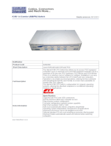
1 23
45
Introduction
Rear View
8
1. Firmware Upgrade Section – Firmware Upgrade Switch : During normal operation and while performing a
fimware upgrade, this switch should be in the NORMAL position. See p. 44 for details about the use of this
switch.
Firmware Upgrade Port : The Firmware Upgrade Cable that transfers the firmware upgrade data from the
administrator’s computer to the GCS1758 plugs into this RJ-11 connector. See p. 44 for firmware
upgrading details.
2. Console Port Section – Ports to plug in your microphone, speakers, monitor, keyboard and mouse are
found here. Each port is marked with an appropriate icon to indicate itself.

Introduction
9
3. CPU Port Section – The cables that link the switch to your computers plug in here. Each CPU port is
comprised of a microphone jack, speaker jack, and KVM data connector.
Note: The shape of these 15-pin connectors has been specifically modified so that only KVM cables
designed to work with this switch can plug in. Do NOT attempt to use ordinary 15 pin VGA connector
cables to link these ports to the computers.
4. Cable Tie Slot – If you want to use a cable tie to gather the cables, you can run it through this
slot to attach it to the unit.
5. Power Jack – The power adapter cable plugs into this jack.

Installation
Before you Begin
1. You must unplug the power cords of any computers
that does not support hot-plugging feature.
2. To prevent damage to your installation make sure
that all devices on the installation are properly
grounded.
10
Single Stage Installation
To set up the single stage installation of GCS1758,
refer to the installation diagrams on the following
page, and do the steps as indicated:
1. Plug your USB keyboard, USB mouse, monitor,
microphone and speakers into the Console USB
Ports located on the unit’s rear panel.
2. Using a KVM cable set, plug the custom SPDB15
connector into any available CPU Port on the
switch and plug the accompanying microphone
and speaker cables into the CPU Port’s
microphone and speaker jacks.
Note: Be sure that all the plugs are in the same
CPU Port sockets (all in Port 1, all in Port 2,
etc.).

Installation
11
3. At the other end of the cable (the computer end):
a) For a computer with USB connections, plug the
USB, video, microphone and speaker cables into
their respective ports on the computer.
b) For a computer with PS/2 connections, plug the
keyboard, mouse, video, microphone and speaker
cables into their respective ports on the computer.

Installation
12
Two Stage Installation
To control even more computers, you can connect
up to eight additional GCS1758 units cascading to
the CPU ports of the first stage unit. As many as 64
computers can be controlled in a complete two
stage installation.
4. Repeat steps 2 - 3 for any other computers you
are connecting up.
5. Plug the power adapter cable into the switch’s
Power Jack, then plug the power adapter into an
AC power source. This completes the single stage
installation, and you can turn on the power to the
computers.

13
2. For each Second Stage unit, plug the power
adapter cable into the switch’s power jack; plug the
power adapter into an AC source.
3. Plug the First Stage unit’s power adapter cable
into its power jack, then plug the power adapter
into an AC source.
4. Turn on the power to all the computers.
Note: The Power On sequence requires that all
third stage units be powered on first. After they are
all on, the Second Stage units must be powered on
next. After all the second stage units are on, the
first stage unit must be powered on. Only after all
the switches have been powered on in this
sequence, can the computers be powered on.
Three Stage Installation
The procedures for setting up a three stage
installation are essentially the same as for a two
stage installation. With a three stage setup, as
many as 512 GCS1758 computers can be controlled
in a complete installation. A table showing the
relation between the number of computers and the
number of switches needed to control them is
provided on p. 45.
Switches cannot be cascaded beyond the third
level. Once you have finished cabling up (see Two/
Three Stage Installation for details, if necessary),
power up according to the following sequence:
1. For each Third Stage unit, plug the power adapter
cable into the switch’s power jack; plug the power
adapter into an AC source.
Installation

Installation
14

Operation
15
Hot Plugging
The Miniview
®
Ultra+ supports hot plugging.
Components can be removed and added back into
the installation by unplugging and replugging their
cables from their respective ports without the need
to shut the switch down. For hot plugging to work
properly, the following procedures must be
observed:
Hot Plugging CPU Ports:
When hot plugging cables from the CPU ports:
1. The cable must be plugged back into the
same
port
it was removed from.
2. After plugging the cable back in, you must
perform a KVM Reset on the First Stage unit (by
pressing the Reset switch In).
Hot Plugging Console Ports:
The unit supports hot plugging of the keyboard,
monitor, and mouse.
Note: If there is no response to mouse and/or PS/2
keyboard input after hot plugging (or at any other
time), simultaneously press and hold Port Select
buttons 1 and 2 on the First Stage unit for 3
seconds to perform a PS/2 Keyboard and PS/2
Mouse reset.

Operation
16
Powering Off:
If it becomes necessary to power off one of the
GCS1758 units, you must do the following:
Shut down all the computers that are attached to the
unit which do not support hot plugging feature, such
as PS/2 computers or computers with Novell OS, etc.
Port ID Numbering:
Each CPU Port on a GCS1758 installation is
assigned a unique
Port ID
. You can directly access
any computer on any level of the installation by
specifying the Port ID of the CPU port that the
computer is connected to - either with the Hotkey
port selection method (see p. 20), or with the OSD
(see p. 27).
The Port ID is a one, two, or three digit number. It is
determined by the Stage Level and CPU Port number
of the switch that a computer is connected to.
The first digit represents the CPU Port number of the
First Stage unit; the second digit represents the CPU
Port number of the Second Stage
unit; the third digit represents the CPU Port number
of the Third Stage unit.

Operation
17
´ A computer attached to a First Stage unit has a
one digit Port ID (from 1-4 for the CS-1754; from 1-
8 for the CS-1758), that corresponds to the CPU
Port number that it is connected to.
´ A computer attached to a Second Stage unit has a
two digit Port ID. The first digit represents the CPU
Port number on the First Stage unit that the
Second Stage unit links back to; the second digit
represents the CPU Port number on the Second
Stage unit that the computer is connected to. For
example, a Port ID of 2 3 would refer to a computer
that is connected to CPU Port 3 of a Second Stage
unit that links back to CPU Port 2 of the First
Stage unit.
´ Likewise, a computer attached to a Third Stage
unit has a three digit Port ID. As in the previous
example, a Port ID of 2 4 1 would refer to a
computer that is connected to CPU Port 1 of a
Third Stage unit, that links back to CPU Port 4 of a
Port Selection:
The Miniview Ultra+ provides three methods to
obtain instant access to any computer in your
installation: Manual,
Hotkey
, and OSD.
• Manual - Simply press the appropriate
Port
Selection Switch
on the GCS1758’s front panel.
After you press the switch, the
Selected
LED
lights to indicate that the port has the KVM
focus. The OSD (see p. 27) automatically
switches to highlight the computer that you
have selected.
Note:
1. On a cascaded installation, you must press
the Port Selection switch on the GCS1758
Second Stage unit, which, in turn, links back to CPU
Port 2 of the First Stage unit.
/