Page is loading ...

QUICKSTART DOC. 6935B (2027065) 05.11
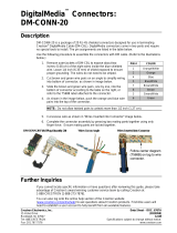
quickstart guide
DM-RX1-1G & DM-TX1-1G
www.crestron.com
888.273.7876 201.767.3400
Specifications subject to
change without notice.
For details, refer to the latest version of the DM-RX1-1G and DM-TX1-1G
DigitalMedia
™
CAT Receiver and Transmitter Operations & Installation
Guides, Doc. 6969 and Doc. 6849.
DigitalMedia
™
CAT Receiver and Transmitter
DM-RX1-1G & DM-TX1-1G
1
Mounting
2
Rear Connections
3
Front Panel Connections
Rear connections for video, data management, control and power as described here are via
DigitalMedia™ Cable (DM-CBL-P) which has been fed through an installed 1-gang electrical
box (not supplied). Refer to the illustrations below and do the following:
1. Confirm that DMNe
t
®
system power is OFF.
2. Strip 3 inches (77 mm) of the DigitalMedia Cable to
expose the three inner cables.
NOTE: For the "D" and "M" cables, do not allow the twisted pairs to untwist for more than
1/2 inch (13 mm).
NOTE: Maintain equal wire lengths within 1/8 inch (3 mm).
3. Strip the outer jacket of the blue “D” cable 1 3/4 inch
(45 mm) from the end. Gather and twist the braid
.
4. Trim the foil shield to 1/2 inch (13 mm). Refer to the
illustration to the right.
5. Remove the white neoprene sheath and separate the
twisted pairs to expose the spline. Cut the spline so
it is nearly flush with the foil shield. Return twisted
pairs to their original position.
6. Neatly wrap the twisted braid around the foil shield.
Only the silver side of the foil shield is conductive.
Refer to the
illustration to the right.
The illustration below provides a basic application for the
DigitalMedia CAT Receiver and Transmitter.
G Black & Ground
B Gray
A Orange
24 Red
11. Route the yellow and gray cables to the other side of the unit and clamp the
prepared cables together to the unit using the supplied clamp and nut.
12. Using a miniature flat head screwdriver (not supplied), make the connections
as specified, using the labels on the unit as a guide.
a. Insert the twisted pairs of the gray DMNet cable into the G B A 24
terminal block as shown in the table to the right, and tighten each
screw base.
b. Insert the twisted pairs of the blue "D" cable into the D terminal block and
tighten each screw base. Refer to the label above the terminal block for
wire locations.
c. Insert the twisted pairs of the yellow "M" cable into the M terminal block
and tighten each screw base. Refer to the label above the terminal block
for wire locations.
13. Remove the pre-cut insulation from the groundiing wire and connect it to the
electrical box or a ground wire in the electrical box (the electrical box must be
earth grounded).
14. On the DM-TX1-1G module, set the DIP switches to reflect the installed cable
type and the desired mode. Refer to the following table. For additional
information, refer to the latest version of the DM-TX1-1G DigitalMedia CAT
Transmitter Operations & Installation Guide (Doc. 6849) available from the
Crestron Web site (www.crestron.com/manuals).
9. Strip the outer jacket of the yellow "M" cable approximately 2 inches (51 mm)
from the end, and
strip the insulation from the ends of each wire, exposing
approximately 3/16 inch (5 mm) of bare copper.
10. Strip the outer jacket of the gray DMNet cable approximately 1 inch (26 mm)
from the end, and strip the insulation from the ends of each wire, exposing
approximately 3/16 inch (5 mm) of bare copper.
Twisted Braid
Must Fully
Contact Inside
of Clamp
DM-TX1-1G
6503433
BRN
WH/BR
ORG
WH/OR
GRN
WH/GR
BLU
WH/B
LU
D
SW1
ON
OFF
SW2
7. Strip the insulation from the ends of each wire, exposing approximately 3/16 inch
(5 mm) of bare copper.
8. Using an adjustable wrench, clamp the prepared cable to the unit as shown in
the following diagram.
D Cable
M Cable
Data/Control
Cable
Assy, DM-TX1-1G Module
(6503433 or 6504686), Qty. 1
Wall Plate With Hardware
(Not Supplied)
Screw, 6-32 X 3/4", Oval Head
(2009684), Qty. 2 Total
Assy, Insert, Black,
(4510566), Qty. 1
1-Gang Electrical Box
(Not Supplied)
Or
Assy, DM-RX1-1G Module
(6503434 or 6504685), Qty. 1
Ground
Wire
NOTE: Braid should wind neatly around foil shield.
Loose braid may cause shorts.
SW1 SW2
DM-CBL DigitalMedia Cable
(DMNet
Master
mode)
Video inactive (DMNet Slave mode)
Assy, Insert, White,
(4512253), Qty. 1
Or
ON
ON
After connecting the DigitalMedia Cable to the
rear panel connectors, attach the ground wire to
the electrical box, and mount the gang receiver
or transmitter in the electrical box.
Crestron, the Crestron logo, DigitalMedia, and DMNet are trademarks
or registered trademarks of Crestron Electronics, Inc. in the United
States and other countries. Other trademarks and trade names may
be used in this document to refer to either the entities claiming the
marks and names or their products. Crestron disclaims proprietary
interest in the marks and names of others.
©2011 Crestron Electronics, Inc.
Twisted Wire Braid
Reserved for factory use only
ON
OFF
OFF
ON
OFF OFF
/