Page is loading ...

QUICKSTART DOC. 6948B (2027114) 11.10
quickstart guide
DM-TX Gang Series
www.crestron.com
888.273.7876 201.767.3400
©2010 Specifications subject to
change without notice.
For details, refer to the latest revision of the DM-TX-200-2G and
DM-TX-400-3G DigitalMedia
™
Transmitter Guide, Doc. 6949.
DigitalMedia
™
Gang Transmitters
All brand names, product names, and trademarks
are the property of their respective owners.
DM-TX Gang Series
1
Rear Panel Connections
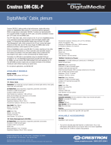
Rear panel connections for video, data management, and control and power are via DigitalMedia™ Cable
(DM-CBL-P) which has been installed into the electrical boxes. Refer to the illustrations below and do the following:
1. Confirm DMNET system power is OFF.
2. Strip approximately 12 inches (305 mm) of the outer jacket from the DM-CBL-P
cable to expose the three inner cables: 'D' (blue), 'M' (yellow), and 'data/control' (gray).
3. Using the illustrations as a guide, route the cables to their connector locations and secure to
the threaded studs mounted on the chassis using strain relief clamps and nuts provided.
4. Strip the outer jacket of the blue 'D' cable 1 3/4 inches (45 mm) from the
end. Gather and twist the braid.
5. Trim the foil shield to 1/2 inch (13 mm). Refer to the illustration to the right.
6. Rem
ove the white neoprene sheath and separate the twisted pairs to expose
the spline. Cut the spline so it is nearly flush with the foil shield. Return twisted
pairs to their original position.
7. Neatly wrap the twisted braid around the foil shield. Only the silver side of the
foil shield is conductive.
NOTE: Braid should wind neatly around foil shield. Loose braid may cause shorts.
8. As shown in the illustrations of the rear panel,
carefully remove approximately
1/2 inch (13 mm) section of the outer jacket of the blue 'D' cable at the clamp
location to expose the shield braid and allow the clamp to establish chassis
ground.
9. Route the twisted pairs to their connector locations (refer to the connector label),
trim to appropriate length and strip the wires 1/8 inch (~3 mm). Insert the wires into
the appropriate terminals and tighten the screws to hold them in place.
NOTE: Maintain equal wire lengths within 1/8 inch (~3 mm).
NOTE: Do not allow the twisted pairs to untwist for more than 1/2 inch (13 mm).
10. Strip approximately 2 inches (51 mm) of the yellow 'M' cable outer jacket.
11 Route the twisted pairs to their connector locations (refer to the connector label),
trim to appropriate length and strip the wires 1/8 inch (~3 mm). Insert the wires
into the terminals and tighten the screws to hold them in place.
12. Remove approximately 1 inch (26 mm) of the gray data/control cable outer
jacket. Trim the foil shield around the orange and gray wires flush to the outer
jacket.
13. Route the insulated wires and the bare ground wire to their connector locations.
Trim to appropriate length and strip the insulated wires 1/8 inch (~3 mm). Insert
the wires into the terminals (the ground wire and the black wire are located
together) and tighten the screws to hold them in place.
Mounting
2
3-Gang Electrical Box
(Not Supplied)
Assy, DM-TX-400-3G Module,
(6503589 or 6504688)
Wall Plate With Hardware
(Not Supplied)
-
D Cable
M Cable
Data/Control
Cable
Ground
Wire
2-Gang Electrical Box
(Not Supplied)
Assy, DM-TX-200-2G Module,
(6503588 or 6504687)
Screws (4) #06-32 x 3/4"
Truss Combo Head (2009211)
Wall Plate With Hardware
(Not Supplied)
D Cable
M Cable
Data/Control
Cable
Ground
Wire
After connecting the DigitalMedia cable to the rear panel connectors, attach the ground wire to
the electrical box or to a wire in the electrical box, and mount the gang transmitter in the
electrical box using the #06-32 x 3/4" screws provided.
DM-CBL-P
DigitalMedia Cable
DM-CBL-P
DigitalMedia Cable
1
DM-TX-400-3G
MADE IN COO
6503589
BRN
WH/BR
ORG
WH/OR
GRN
WH/GR
BLU
WH/BLU
D
BRN
WH/BR
ORG
WH/OR
GRN
WH/GR
BLU
WH/BLU
M
DM-TX-400-3G
DM-TX-200-2G
MADE IN COO
6503588
BRN
WH/BR
ORG
WH/OR
GRN
WH/GR
BLU
WH/BLU
D
BRN
WH/BR
ORG
WH/OR
GRN
WH/GR
BLU
WH/BLU
M
DM-TX-200-2G
G
B
A
24
G Black & Ground
B Gray
A Orange
24 Red
Data/Control
Connections
Remove approximately
1/2 inch (13 mm) of the outer
jacket to expose the shield
braid. Use strain relief clamp
to establish chassis ground.
Screws (6) #06-32 x 3/4"
Truss Combo Head (2009211)
CAUTION: Excess wire pinched between the unit and electrical box could cause a short. Make sure
all excess wire is completely inside the electrical box, not between the box and the side of the unit.

QUICKSTART DOC. 6948B (2027114) 11.10
quickstart guide
DM-TX Gang Series
www.crestron.com
888.273.7876 201.767.3400
©2010 Specifications subject to
change without notice.
For details, refer to the latest revision of the DM-TX-200-2G and
DM-TX-400-3G DigitalMedia
™
Transmitter Guide, Doc. 6949.
DigitalMedia
™
Gang Transmitters
All brand names, product names, and trademarks
are the property of their respective owners.
DM-TX Gang Series
3
Front Panel Connections / Controls / Indicators
Refer to the illustrations below and use appropriate cables (not
supplied) to connect audio, video, data management, and control
sources to the DigitalMedia gang transmitters.
Refer to the adjacent table for a description of the LED indications.
DM-TX-200-2G Front Panel Connections
DM-TX-400-3G Front Panel Connections
LAPTOP
KEYBOARD
& MOUSE
HDMI
HDMI
Audio
(Optional)
Audio
(Optional)
USB
USB
Composite
&
Analog Audio
Component
&
SPDIF
2
CONTROL/
INDICATOR
DESCRIPTION
PWR
RESET
SETUP
DM LINK
HDMI
PC
YPbPr
VID
Green led, indicates operating power supplied via DMNet
Miniature recessed pushbutton for hardware reset
Red LED and 1 miniature recessed pushbutton for Ethernet auto-discovery
Green LED, indicates connection to a downstream DM device
Green LED, indicates HDMI input selected
Green LED, indicates PC input selected
Green LED, indicates YPbPr input selected
Green LED, indicates VID input selected
DM-TX-200-2G / 400-3G Front Panel Controls & Indicators
DM-TX-200-2G DM-TX-400-3G
X X
X X
X X
X X
X X
X X
X
X
LAPTOP
KEYBOARD
& MOUSE
/


