Page is loading ...

Crestron DM-MD6X1
6X1 DigitalMedia™ Switcher
Operations Guide

This document was prepared and written by the Technical Documentation department at:
Crestron Electronics, Inc.
15 Volvo Drive
Rockleigh, NJ 07647
1-888-CRESTRON
Regulatory Compliance
This product is Listed to applicable UL Standards and requirements by Underwriters Laboratories Inc.
Federal Communications Commission (FCC) Compliance Statement
This device complies with part 15 of the FCC Rules. Operation is subject to the following conditions:
(1) This device may not cause harmful interference and (2) this device must accept any interference received,
including interference that may cause undesired operation.
CAUTION: Changes or modifications not expressly approved by the manufacturer responsible for compliance
could void the user’s authority to operate the equipment.
NOTE: This equipment has been tested and found to comply with the limits for a Class B digital device,
pursuant to part 15 of the FCC Rules. These limits are designed to provide reasonable protection against harmful
interference in a residential installation. This equipment generates, uses and can radiate radio frequency energy
and, if not installed and used in accordance with the instructions, may cause harmful interference to radio
communications. However, there is no guarantee that interference will not occur in a particular installation. If
this equipment does cause harmful interference to radio or television reception, which can be determined by
turning the equipment off and on, the user is encouraged to try to correct the interference by one or more of the
following measures:
Reorient or relocate the receiving antenna
Increase the separation between the equipment and receiver
Connect the equipment into an outlet on a circuit different from that to which the receiver is connected
Consult the dealer or an experienced radio/TV technician for help
This Class B digital apparatus complies with Canadian ICES-003.
Cet appareil numérique de la classe B est conforme à la norme NMB-003 du Canada.
Industry Canada (IC) Compliance Statement
As of the date of manufacture, the DM-MD6X1 has been tested and found to comply with specifications for CE
marking and standards per EMC and Radiocommunications Compliance Labelling.
This device includes an aggregation of separate independent works that are each generally copyrighted by Crestron Electronics, Inc., with all rights
reserved. One of those independent works, Linux Bridge Project, is copyrighted under the GNU GENERAL PUBLIC LICENSE, Version2,
reproduced in “GNU General Public License” on page 36, where the corresponding source code is available at: ftp://ftp.crestron.com/gpl.
Dolby is a registered trademark of Dolby Laboratories. DTS is a registered trademark of DTS, Inc.
HDMI is a trademark or registered trademarks of HDMI Licensing LLC in the United States and other countries.
©2011 Crestron Electronics, Inc.

Crestron DM-MD6X1 6X1 DigitalMedia™ Switcher
Contents
6X1 DigitalMedia™ Switcher: DM-MD6X1 1
Introduction ...............................................................................................................................1
Features and Functions................................................................................................ 1
Applications.................................................................................................................4
Internal Block Diagram ............................................................................................... 5
Specifications ..............................................................................................................6
Physical Description..................................................................................................10
Setup ........................................................................................................................................16
Network Wiring.........................................................................................................16
HDCP Signal Path ..................................................................................................... 16
Ethernet Setup ...........................................................................................................17
Identity Code ............................................................................................................. 18
Installation................................................................................................................. 18
Hardware Hookup .....................................................................................................20
Programming Software............................................................................................................24
Earliest Version Software Requirements for the PC .................................................24
Programming with Crestron SystemBuilder.............................................................. 24
Programming with SIMPL Windows ........................................................................ 24
Uploading and Upgrading........................................................................................................ 28
Establishing Communication..................................................................................... 28
Programs and Firmware ............................................................................................29
Program Checks ........................................................................................................ 30
DMTool..................................................................................................................... 30
Operation .................................................................................................................................31
Problem Solving ......................................................................................................................32
Check Network Wiring..............................................................................................33
Reference Documents................................................................................................34
Further Inquiries ........................................................................................................34
Future Updates ..........................................................................................................34
Return and Warranty Policies .................................................................................................. 35
Merchandise Returns / Repair Service ...................................................................... 35
CRESTRON Limited Warranty.................................................................................35
GNU General Public License ..................................................................................................36
Operations Guide – DOC. 6850D Contents • i


Crestron DM-MD6X1 6X1 DigitalMedia™ Switcher
6X1 DigitalMedia™ Switcher:
DM-MD6X1
Introduction
The Crestron
®
DM-MD6X1 DigitalMedia™ switcher delivers an incredibly versatile
and cost-effective solution for managing a complete range of digital and analog AV
sources in a small conference room or classroom, or as part of a larger DigitalMedia
distribution system. High-resolution computer signals, standard and high-definition
video, stereo analog and digital multichannel audio sources are all handled by the
DM-MD6X1, providing a perfect standalone switcher or multiformat interface for
installation in an equipment rack or presentation lectern.
Additional DigitalMedia inputs and output allow the DM-MD6X1 to work with the
full line of Crestron DM
®
transmitters, switchers, receivers, and room controllers,
affording extensive capabilities for routing and distributing all of today’s multimedia
AV signal types throughout a single room or larger facility. Combining DM
technology with a full complement of analog connections affords a perfect signal
converter for integrating DigitalMedia into any analog-based system such as
Crestron MPS, QuickMedia
®
, and the CEN-RGBHV Series (all sold separately).
Features and Functions
• DigitalMedia switcher and interface
• HDMI
®
, RGB, and multiformat BNC video inputs
• Balanced analog and S/PDIF audio inputs
• 3 DM CAT inputs and 1 DM CAT output
• HDMI and analog stereo audio outputs
• Integrated USB HID (Human Interface Device) keyboard/mouse
extender and switch
• Supports HDMI with multichannel lossless audio
• Supports video resolutions up to WUXGA 1920 x 1200 and HD
1080p60
• Detects and reports detailed video and audio input information
• Performs automatic AV signal format management via EDID
(Continued on following page)
Operations Guide – DOC. 6850D 6X1 DigitalMedia™ Switcher: DM-MD6X1 • 1

6X1 DigitalMedia™ Switcher Crestron DM-MD6X1
Features and Functions
(Continued)
• Allows cable length to 450 feet (~137 meters) using DigitalMedia
Cable
1
• QuickSwitch HD
®
technology achieves low-latency HDMI switching
• Enables device control via CEC
• Supports 3D HDTV via DM in/out
• Easy setup and diagnostics tools via software
• Extends the life of analog-based AV systems
• Built-in power distribution for DM transmitters and room controller
• 2-space 19-inch rack-mountable
Multimedia Computer/AV Switcher
Inputs on the DM-MD6X1 include multi-format BNC video, RGB, HDMI
®
,
balanced line level and S/PDIF digital audio. The HDMI input supports HDMI with
HDCP, handling WUXGA computer resolutions and 1080p60 HDTV with
multichannel lossless audio. The HDMI input can also handle DVI and DisplayPort
Multimode signals using an appropriate adapter or dongle
2
. The RGB input handles
analog RGB signals up to WUXGA 1920x1200 pixels, as well as component video
up to 1080p60
3
. The multi-format BNC input also accepts component HDTV signals
up to 1080p60, as well as standard definition NTSC/PAL composite and S-video.
Dedicated audio inputs include two stereo balanced line level analog and one S/PDIF
coaxial digital.
Additional inputs are easily added at locations up to 450 feet (~137 m)
1
away using
DM Transmitters. Three CAT-type DM inputs are provided on the DM-MD6X1,
accepting inputs from individual DM Transmitters as well as other DM switchers. A
single DM CAT output is provided to drive a DM Receiver/Room Controller at the
display location, or to feed another DM switcher. HDMI and analog audio outputs
are also included to feed a local video display and audio system. The analog stereo
output includes professional balanced terminals and programmable volume control.
DigitalMedia
As the leader in HDMI and control system technologies, Crestron has developed
DigitalMedia, the first complete HD AV distribution system that takes HDMI to a
higher level, and allows virtually any mix of AV sources to be distributed throughout
the home, office, school, or virtually any other facility.
DigitalMedia distributes uncompressed digital video and audio signals up to 450 feet
(~137 m) using DM cable
1
. DigitalMedia thoughtfully manages all of the different
signals and devices, matching each source's output to the capabilities of the selected
display(s) without using scaling or compression. Every signal is preserved in its
native video resolution and audio format, ensuring a pure, lossless signal path
throughout.
1. For DigitalMedia CAT wiring, use DM-CBL DigitalMedia Cable. Up to two DM Repeaters (model
DM-DR, sold separately) may be required. Refer to the latest version of the Creston DigitalMedia
Design Guide (Doc. 4789) for complete wiring guidelines. It is available from the Crestron Web site
(www.crestron.com/dmresources
).
2. HDMI requires an appropriate adapter or interface cable to accommodate a DVI or DisplayPort
Multimode signal. CBL-HD-DVI and CBL-DP-HD interface cables available separately.
3. The RGB input can accept component, composite, and S-video signals via direct interface to Crestron
MPS Series products, or through an appropriate adapter (all sold separately). Input sync detection is
not provided for composite or S-video signal types through the RGB connection.
2 • 6X1 DigitalMedia™ Switcher: DM-MD6X1 Operations Guide – DOC. 6850D

Crestron DM-MD6X1 6X1 DigitalMedia™ Switcher
QuickSwitch HD
®
Technology
Crestron exclusive QuickSwitch HD
®
technology minimizes the annoying switching
latency that plagues typical HDMI switchers. QuickSwitch HD achieves very fast
switching of HDMI signals by maintaining a constant HDCP connection with each
HDMI device in the system, eliminating the need to re-authenticate each time a
different source is selected.
Keyboard/Mouse Extender
The DM-MD6X1 also functions as a keyboard/mouse extender and switcher,
allowing a computer or other USB HID-compliant host device connected to the
DM-MD6X1 to be controlled by a keyboard and mouse at the display location using
a DM-RMC-100-1 room controller (sold separately), or at a presenter’s location
using select DM transmitters.
EDID Format Management
The DM-MD6X1 allows for management of the EDID (Extended Display
Identification Data) information that passes between the display devices and input
sources in the system. Using Crestron Toolbox™ software, the format and resolution
capabilities of each device can be assessed and managed through the DM-MD6X1,
ensuring reliable operation by instructing sources to output only the resolutions and
formats that can be handled by the displays and system wiring.
CEC Embedded Device Control
The primary objective of every Crestron system is to enable precisely the control
desired for a seamless user experience. DigitalMedia provides an alternative to
conventional IR and RS-232 device control by harnessing the CEC (Consumer
Electronics Control) signal embedded in HDMI. Through its connection to the
control system, the DM-MD6X1 provides a gateway for controlling AV devices
right through their HDMI connections, potentially eliminating the need for any
dedicated control wires or IR probes. Through proper CEC signal management,
DigitalMedia allows you to take control of each device in the system as you like.
Easy Setup
The DM-MD6X1 is designed to be placed on a shelf or mounted in an equipment
rack or lectern. The front panel provides basic operation right out of the box.
User-friendly setup and troubleshooting tools are provided via Crestron Toolbox
software, performing automatic input and output configuration while letting the
installer make intelligent design decisions along the way. The switcher even tests and
measures the length of each DM cable, automatically making the appropriate
calibrations for optimal signal transmission to each DM device.
Operations Guide – DOC. 6850D 6X1 DigitalMedia™ Switcher: DM-MD6X1 • 3

6X1 DigitalMedia™ Switcher Crestron DM-MD6X1
A Digital Upgrade for Legacy Systems
The DM-MD6X1 also affords a perfect signal converter for integrating DigitalMedia
with analog-based systems like Crestron MPS, QuickMedia
®
, and the CEN-RGBHV
Series (all sold separately). A simple HD15 VGA cable connected between the
output of an MPS system and the input of the DM-MD6X1 allows every RGB,
component, S-video, and composite video input on the MPS to be converted to
DigitalMedia*. Analog audio is converted similarly through a simple balanced stereo
audio cable. The DM-MD6X1’s HDMI and DM inputs may also be used to expand
the input capabilities of the MPS system to handle digital AV sources, and its analog
audio output can easily be fed into any spare input on the MPS to allow the digital
audio signals to be amplified and controlled through the MPS system.
Applications
The following diagram shows a DM-MD6X1 in a lecture hall application.
DM-MD6X1 in a Lecture Hall Application
* The RGB input can accept component, composite, and S-video signals via direct interface to Crestron
MPS Series products, or through an appropriate adapter (sold separately). Input sync detection is not
provided for composite or S-video signal types through the RGB connection.
4 • 6X1 DigitalMedia™ Switcher: DM-MD6X1 Operations Guide – DOC. 6850D

Crestron DM-MD6X1 6X1 DigitalMedia™ Switcher
Internal Block Diagram
The following diagram represents the signal path through the DM-MD6X1.
Internal Block Diagram of the DM-MD6X1
The following table shows valid audio breakaway routes through the DM-MD6X1. If
an invalid route is established, video will be transmitted but audio will not.
Audio
AUDIO IN 1 /
S/PDIF IN 3
AUDIO IN 2 HDMI 3 DM 4 DM 5 DM 6
VIDEO IN
1
RGB 2
HDMI 3
DM 4
DM 5
Video
DM 6
Operations Guide – DOC. 6850D 6X1 DigitalMedia™ Switcher: DM-MD6X1 • 5

6X1 DigitalMedia™ Switcher Crestron DM-MD6X1
Specifications
Specifications for the DM-MD6X1 are listed in the following table.
DM-MD6X1 Specifications
SPECIFICATION DETAILS
Video
Switcher
6x1 combination digital/analog switch,
Crestron QuickSwitch HD
Input Signal Types
DM CAT (DigitalMedia over shielded
twisted-pair copper wire), HDMI, DVI
1
,
DisplayPort Multimode
1
, RGB, component
(YP
b
P
r
)
2
, S-video (Y/C)
2
, composite
2
Output Signal Types DM CAT, HDMI, DVI
1
Formats
HDMI, DVI, HDCP content protection
support, 3D (via DM inputs only), RGBHV
up to UXGA/WUXGA, HDTV up to
1080p60, NTSC or PAL
Input Resolutions, HDMI,
Progressive
640 x 480 @ 60 Hz
720 x 480 @ 60 Hz (480p)
720 x 576 @ 50 Hz (576p)
800 x 600 @ 60 Hz
848 x 480 @ 60 Hz
852 x 480 @ 60 Hz
854 x 480 @ 60 Hz
1024 x 768 @ 60 Hz
1024 x 852 @ 60 Hz
1024 x 1024 @ 60 Hz
1280 x 720 @ 50 Hz (720p50)
1280x720 @ 60 Hz (720p60)
1280 x 768 @ 60 Hz
1280 x 800 @ 60 Hz
1280 x 960 @ 60 Hz
1280 x 1024 @ 60 Hz
1360 x 768 @ 60 Hz
1365 x 1024 @ 60 Hz
1366 x 768 @ 60 Hz
1400 x 1050 @ 60 Hz
1440 x 900 @ 60 Hz
1600 x 900 @ 60 Hz
1600 x 1200 @ 60 Hz
1680 x 1050 @ 60 Hz
1920 x 1080 @ 24 Hz (1080p24)
1920 x 1080 @ 25 Hz (1080p25)
1920 x 1080 @ 50 Hz (1080p50)
1920 x 1080 @ 60 Hz (1080p60)
1920 x 1200 @ 60 Hz
2048 x 1080 @ 24 Hz
2048 x 1152 @ 60 Hz
plus any other resolution allowed by HDMI
up to 165 MHz pixel clock
Input Resolutions, HDMI,
Interlaced
720 x 480 @ 30 Hz (480i)
720 x 576 @ 25 Hz (576i)
1920 x 1080 @ 25 Hz (1080i25)
1920 x 1080 @ 30 Hz (1080i30)
plus any other resolution allowed by HDMI
up to 165 MHz pixel clock
(Continued on following page)
6 • 6X1 DigitalMedia™ Switcher: DM-MD6X1 Operations Guide – DOC. 6850D

Crestron DM-MD6X1 6X1 DigitalMedia™ Switcher
DM-MD6X1 Specifications (Continued)
SPECIFICATION DETAILS
Video (Continued)
Input Resolutions, RGB
640 x 480 @ 60 Hz
720 x 480 @ 60 Hz (480p)
720 x 576 @ 50 Hz (576p)
800 x 600 @ 60 Hz
848 x 480 @ 60 Hz
1024 x 768 @ 60 Hz
1280 x 720 @ 50 Hz (720p50)
1280 x 720 @ 60 Hz (720p60)
1280 x 768 @ 60 Hz
1280 x 800 @ 60 Hz
1280 x 960 @ 60 Hz
1280 x 1024 @ 60 Hz
1360 x 768 @ 60 Hz
1366 x 768 @ 60 Hz
1400 x 1050 @ 60 Hz
1440 x 900 @ 60 Hz
1600 x 1200 @ 60 Hz
1680 x 1050 @ 60 Hz
1920 x 1080 @ 24 Hz (1080p24)
1920 x 1080 @ 50 Hz (1080p50)
1920 x 1080 @ 60 Hz (1080p60)
1920 x 1200 @ 60 Hz
2048 x 1080 @ 24 Hz
2048 x 1152 @ 60 Hz
Input Resolutions, Component
480i
576i
480p
576p
720p50
720p60
1080i25 (1125 lines)
1080i30
1080p30
1080p50 (1125 lines)
1080p60
Input Resolutions, Composite
and S-video
480i
576i
Output Resolutions Matched to inputs
Analog-To-Digital Conversion 10-bit 165 MHz per each of three channels
Audio
Switcher
6x1 combination digital/analog switch,
limited audio breakaway
3
; independent
input compensation and master volume
adjustment for analog output
Input Signal Types
DM CAT, HDMI, DisplayPort Multimode
1
,
S/PDIF coaxial, analog stereo
Output Signal Types DM CAT, HDMI, analog stereo
Formats, HDMI and S/PDIF
Dolby
®
Digital, Dolby Digital EX, DTS
®
,
DTS-ES, DTS 96/24, 2ch PCM
Formats, HDMI only Up to 8ch PCM
Formats, Analog Stereo 2-Channel
(Continued on following page)
Operations Guide – DOC. 6850D 6X1 DigitalMedia™ Switcher: DM-MD6X1 • 7

6X1 DigitalMedia™ Switcher Crestron DM-MD6X1
DM-MD6X1 Specifications (Continued)
SPECIFICATION DETAILS
Audio (Continued)
Analog-To-Digital Conversion 24-bit 48 kHz
Digital-To-Analog Conversion 24-bit 48 kHz
Volume Gain Range
(analog out)
-80 dB to 0 dB, adjustable from 0% to 100%
Input Compensation
(analog out)
±10 dB per input
Performance (analog)
Frequency Response
S/N Ratio
THD+N
Stereo Separation
20 Hz to 20 kHz ±0.75 dB
>90 dB, 20 Hz to 20 kHz A-weighted
<0.05% @ 1 kHz
>90 dB
Communications
DigitalMedia
DM CAT, DMNet, HDCP management,
EDID format management, CEC
Ethernet
10BASE-T/100BASE-TX, auto-switching,
auto-negotiating, auto-discovery, full/half
duplex, TCP/IP, UDP/IP, CIP, DHCP, RSTP
USB Supports USB HID class devices
Ethernet Switch
Provides (1) onboard
10BASE-T/100BASE-TX Ethernet port,
(1) internal 10BASE-T/100BASE-TX
Ethernet port for the switcher, and
(4) remote 10BASE-T/100BASE-TX
Ethernet ports via select outboard devices
Power Requirements
Main Power 90 Watts @ 100-240 Volts AC, 50/60 Hz
Available DMNet Power
30 Watts (1.25 Amps @ 24 Volts DC) from
internal power supply
Default IP ID 03
Minimum 2-Series Control
System Update File
4, 5, 6
Version 4.003.0015 or later
Environmental
Temperature 32° to 104°F (0° to 40°C)
Humidity 10% to 90% RH (non-condensing)
Heat Dissipation 307 BTU/hr
Enclosure
Chassis
Metal with black finish, vented sides,
fan-cooled
Faceplate
Extruded aluminum, black finish with
polycarbonate label overlay
Mounting
Freestanding or 2U 19-inch rack-mountable
(adhesive feet and rack ears included)
(Continued on following page)
8 • 6X1 DigitalMedia™ Switcher: DM-MD6X1 Operations Guide – DOC. 6850D

Crestron DM-MD6X1 6X1 DigitalMedia™ Switcher
DM-MD6X1 Specifications (Continued)
SPECIFICATION DETAILS
Dimensions
Height 3.47 in (89 mm) without feet
Width
17.03 in (433 mm)
19.00 in (483 mm) with ears
Depth 12.21 in (310 mm)
Weight 7.5 lb (3.4 kg)
Available Accessories
CBL-DP-HD
Crestron Certified DisplayPort to HDMI
Interface Cable
CBL-HD Crestron Certified HDMI Interface Cable
CBL-HD-DVI
Crestron
Certified HDMI to DVI Interface
Cable
CBL-RCA
Crestron
Certified RCA Coaxial Digital Audio
Interface Cable
CBL-VGA
Crestron Certified DB15HD Computer VGA
Interface Cable
DM-CBL DigitalMedia Cable
DM-CONN DigitalMedia Cable Connector
DM-DR DigitalMedia CAT Repeater
MP-WP130
Media Presentation Wall Plate - DB15HD
Computer VGA with Mini-TRS Stereo Audio,
Bulkhead
MP-WP131
Media Presentation Wall Plate - DB15HD
Computer VGA w/Mini-TRS Stereo Audio,
Breakout
MP-WP140
Media Presentation Wall Plate – DVI with
Mini-TRS Stereo Audio
MP-WP150
Media Presentation Wall Plate - HDMI with
Mini-TRS Stereo Audio
MP-WP152 Media Presentation Wall Plate – HDMI
MP-WP160
Media Presentation Wall Plate - DisplayPort
with Mini-TRS Stereo Audio
MP-WP162 Media Presentation Wall Plate – DisplayPort
MP-WP185
Media Presentation Wall Plate - Crestron
DigitalMedia CAT with DMNet
1. HDMI requires an appropriate adapter or interface cable to accommodate a DVI or DisplayPort
Multimode signal. CBL-HD-DVI and CBL-DP-HD interface cables available separately.
2. The RGB input can accept component, composite, and S-video signals via direct interface to Crestron
MPS Series products, or through an appropriate adapter (not included). Input sync detection is not
provided for composite or S-video signal types through the RGB connection.
3. Audio breakaway capabilities and limitations: AUDIO/SPDIF IN 1 and AUDIO IN 2 may each be
switched freely regardless which video input is selected; HDMI IN 3 audio may be switched freely
only when HDMI IN 3 video, or any DM IN video input, is selected; HDMI IN 3 audio cannot be
selected when VIDEO IN 1 or RGB IN 2 video inputs are selected; DM IN 4, DM IN 5, and
DM IN 6 audio may each be switched freely except when any other numbered DM IN video input is
selected; AUDIO IN 1 and SPDIF IN 1 inputs are mutually exclusive.
4. The latest software versions can be obtained from the Crestron Web site. Refer to the NOTE
following these footnotes.
5. Crestron 2-Series control systems include the AV2 and PRO2. Consult the latest Crestron Product
Catalog for a complete list of 2-Series control systems.
Operations Guide – DOC. 6850D 6X1 DigitalMedia™ Switcher: DM-MD6X1 • 9

6X1 DigitalMedia™ Switcher Crestron DM-MD6X1
6. When loading firmware through the RS-232 port of the control system, be sure that the baud rate is at
38400 (Cresnet
®
speed) or lower. Otherwise, Toolbox may post the “Transfer Failed” message.
NOTE: Crestron software and any files on the Web site are for authorized Crestron
dealers and Crestron Authorized Independent Programmers (CAIP) only. New users
may be required to register to obtain access to certain areas of the site (including the
FTP site).
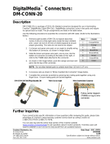
Physical Description
This section provides information on the connections, controls and indicators
available on your DM-MD6X1.
DM-MD6X1 Physical View
DM-MD6X1 Physical View
DM-MD6X1 Overall Dimensions (Front View)
3.47 in
(89 mm)
17.03 in
(433 mm)
7654321
10 • 6X1 DigitalMedia™ Switcher: DM-MD6X1 Operations Guide – DOC. 6850D

Crestron DM-MD6X1 6X1 DigitalMedia™ Switcher
DM-MD6X1 Overall Dimensions (Top View)
DM-MD6X1 Overall Dimensions (Rear View)
Operations Guide – DOC. 6850D 6X1 DigitalMedia™ Switcher: DM-MD6X1 • 11

6X1 DigitalMedia™ Switcher Crestron DM-MD6X1
Connectors, Controls & Indicators
#
CONNECTORS
1
,
CONTROLS &
INDICATORS
DESCRIPTION
1
COMPUTER (front)
(1) USB Type B female
USB 1.1 computer console port
(6 ft cable included)
PIN DESCRIPTION
1 +5 VDC
2 Data -
3 Data +
4 Ground
2 PWR LED
(1) Green LED, indicates operating power
supplied via main power input
3 USB HID DISABLED
(1) Red LED, indicates the COMPUTER port
is in use, causing USB HID to be disabled
4 RESET
(1) Recessed miniature push button for
hardware reset, reboots the switcher
5
SYNC
(Button and LED)
(1) Push button and red LED, selects Sync
mode so the INPUTS LEDs indicate input
signal presence
6
ROUTE
(Button and LED)
(1) Push button and red LED, selects Route
mode to allow routing changes
7
INPUTS 1 – 6
(Buttons and LEDs)
(6) Push buttons and red LEDs, select input
for routing
8
VIDEO IN 1
(3) BNC female comprising (1) auto-sensing
multi-format analog video input;
Signal Types: Component (YP
b
P
r
), S-video
(Y/C), or composite input;
Input Level: 1 V
p-p
nominal
Input Impedance: 75 Ohms nominal
9
RGB IN 2
2
(1) DB15HD female, RGB (VGA) or
component (YP
b
P
r
) video input
3;
Formats: RGBHV, RGBS, RG
s
B, YP
b
P
r
;
Input Levels: 0.5 to 1.5 V
p-p
with built-in DC
restoration
Input Impedance: 75 Ohms
Sync Input Type: Autodetect RGBHV, RGBS,
RG
s
B, YP
b
P
r
Sync Input Level: 3 to 5 V
p-p
Sync Input Impedance: 1k Ohms
10
HDMI IN 3
(1) 19-pin Type A HDMI female;
HDMI digital video/audio input
11
DM IN D/M (4 – 6)
4, 5, 6
(3) DM CAT inputs, each composed of
(2) 8-pin RJ-45 female, shielded;
Connect to DM CAT outputs of DM
transmitters or other DM devices via
DM-CBL cable
(Continued on following page)
12 • 6X1 DigitalMedia™ Switcher: DM-MD6X1 Operations Guide – DOC. 6850D

Crestron DM-MD6X1 6X1 DigitalMedia™ Switcher
Connectors, Controls & Indicators (Continued)
#
CONNECTORS
1
,
CONTROLS &
INDICATORS
DESCRIPTION
12
DM OUT D/M
4, 5, 6
(1) DM CAT output composed of (2) 8-pin
RJ-45 female, shielded;
Connect to DM CAT input of a DM
receiver/room controller, switcher, or other
DM device via DM-CBL cable
13
HDMI OUT
(1) 19-pin Type A HDMI female;
HDMI digital video/audio output;
Carries same audio and video signals as
DM OUT
14
USB HID
(1) USB Type B female;
USB 1.1 device port for connection to the
USB host interface of a computer or other
USB HID-compliant host device
15
LAN
6
GREEN
LED
YELLOW
LED
PIN 8
PIN 1
(1) 8-pin RJ-45 female with two LED
indicators;
10BASE-T/100BASE-TX Ethernet port;
Green LED indicates link status;
Yellow LED indicates Ethernet activity
PIN SIGNAL PIN SIGNAL
1 TX + 5 N/C
2 TX - 6 RX -
3 RX + 7 N/C
4 N/C 8 N/C
16
SETUP (rear)
(Button and LED
(1) Red LED and (1) miniature recessed
push button for Ethernet auto-discovery
17
AUDIO IN 1 – 2
(2) 5-pin 3.5 mm detachable terminal blocks;
Balanced/unbalanced stereo line-level
inputs;
AUDIO IN 1 and SPDIF IN 1 inputs are
mutually exclusive;
Input Impedance: 24k Ohms
balanced/unbalanced
Balanced Input Level: 4 V
rms
maximum
Unbalanced Input Level: 2 V
rms
maximum
18
SPDIF IN 1
(1) RCA female, S/PDIF coaxial digital audio
input;
SPDIF IN 1 and AUDIO IN 1 inputs are
mutually exclusive;
Input Impedance: 75 Ohms
19
AUDIO OUT
7
(1) 5-pin 3.5 mm detachable terminal block;
Balanced/unbalanced stereo line-level
output, variable level;
Output Impedance: 200 Ohms balanced,
100 Ohms unbalanced
Maximum Output Level: 4 V
rms
balanced,
2 V
rms
unbalanced
(Continued on following page)
Operations Guide – DOC. 6850D 6X1 DigitalMedia™ Switcher: DM-MD6X1 • 13

6X1 DigitalMedia™ Switcher Crestron DM-MD6X1
Connectors, Controls & Indicators (Continued)
#
CONNECTORS
1
,
CONTROLS &
INDICATORS
DESCRIPTION
20
DM IN 24 A B G
(4-6)
8, 9, 10
(3) 4-pin 3.5 mm detachable terminal blocks,
DMNet ports;
Connects to DMNet ports of DM transmitters
or other DM devices via DM-CBL cable
4
21
DM OUT 24 A B G
8, 9, 10
(1) 4-pin 3.5 mm detachable terminal block,
DMNet port;
Connects to DMNet port of a DM
receiver/room controller, switcher, or other
DM device via DM-CBL cable
4
22
EXT PWR
10
(1) 3-pin 3.5 mm detachable terminal block,
power selection port;
Connects to an external power supply
11
, or
to the internal power source via a jumper, to
power the DM devices connected to
DM IN 4 – 6 and DM OUT;
Maximum Load: 75 Watts
(3.13 Amps @ 24 Volts DC) total for all ports
when connected to external power supply
11
,
otherwise limited to available DMNet power
(refer to “Power Requirements” in the
“Specifications” table which begins on page
6).
23
100-240V ~2.3A
50/60Hz
(1) IEC C14 male chassis plug, main power
input;
Mates with removable power cord, included
24
G
(1) 6-32 screw, chassis ground lug
1. Interface connectors for 24 A B G, EXT PWR, AUDIO IN and AUDIO OUT ports are provided
with the unit.
2. Refer to the following table for the RGB connector pinouts.
PIN # RGB YP
b
P
r
S-VIDEO COMPOSITE
1 R P
r
C
2 G Y Y
3 B P
b
Comp
13 H
14 V
3. The RGB input can accept component, composite and S-video signals via direct interface to Crestron
MPS Series products (sold separately) or through an appropriate adapter (not included). Input sync
detection is not provided for composite or S-video signal types through the RGB connection.
14 • 6X1 DigitalMedia™ Switcher: DM-MD6X1 Operations Guide – DOC. 6850D

Crestron DM-MD6X1 6X1 DigitalMedia™ Switcher
4. For DigitalMedia CAT wiring, use DM-CBL DigitalMedia Cable. Up to two DM Repeaters (model
DM-DR, sold separately), may be required. Refer to the latest version of the Crestron DigitalMedia
Design Guide (Doc. 4789) for complete wiring guidelines.
5. The DM OUT port consists of two separate RJ-45 connectors labeled D and M. The D port carries
HDMI signal. The M port carries data. Refer to the following table for the connector pinouts.
18
PIN # WIRE COLOR
1 Orange/White
2 Orange
3 Green/White
4 Blue
5 Blue/White
6 Green
7 Brown/White
8 Brown
6. To determine which is pin 1 on the cable, hold the cable so the end of the eight pin modular jack is
facing away from you, with the clip down and copper side up. Pin 1 is on the far left.
7. The source gain compensation only has an effect on the analog audio output (AUDIO OUT) and has
no effect on the DM or HDMI outputs. In addition, the total gain at the output will never exceed 0 dB,
as the total output range is –80 dB to 0 dB. This signifies that a +10 dB input compensation will start
to decrease to 0 dB as the output volume increases from –10 dB to 0 dB.
8. DMNet wiring is not compatible with Cresnet wiring. DMNet wiring cannot be daisy chained.
9. Refer to the following table for the 24 A B G connector pinouts.
PIN # SIGNAL DESCRIPTION WIRE COLOR
G Ground DC Ground Black
B DMNet- DMNet Grey
A DMNet+ DMNet Orange
24 24V DC DC Power Red
10. If a DM switcher or other DM device is supplying power and is connected to a DM port of the
DM-MD6X1 or other DM midpoint, then the +24V wire between the DM device and the
DM-MD6X1 must be disconnected. The A B G wires must remain connected.
11. For external DMNet power, use a Crestron CNPWS-75, C2N-SPWS300 (both sold separately), or
other Cresnet power supply as required. Do not interconnect DMNet with Cresnet.
Operations Guide – DOC. 6850D 6X1 DigitalMedia™ Switcher: DM-MD6X1 • 15

6X1 DigitalMedia™ Switcher Crestron DM-MD6X1
Setup
Network Wiring
When wiring the DM network, consider the following:
NOTE: DMNet wiring and Cresnet
®
wiring are not compatible.
• Use Crestron Certified Wire.
• Use Crestron power supplies for Crestron equipment.
• Provide sufficient power to the system.
CAUTION: Insufficient power can lead to unpredictable results or damage
to the equipment. Use the Crestron Power Calculator to help calculate how
much power is needed for the system (www.crestron.com/calculators
).
• For DigitalMedia CAT wiring, use DM-CBL DigitalMedia Cable. Up to
two DM Repeaters (model DM-DR, sold separately) may be required. Refer
to the latest revision of the Crestron DigitalMedia Design Guide (Doc.
4789) for complete wiring guidelines.
The DM-MD6X1 can also use high-speed Ethernet for communications between the
device and a control system, computer, media server and other IP-based devices. For
general information on connecting Ethernet devices in a Crestron system, refer to the
latest version of the Crestron e-Control
Reference Guide (Doc. 6052), which is
available from the Crestron Web site (www.crestron.com/manuals
). For information
specifically related to Ethernet connectivity using DigitalMedia devices, refer to the
latest version of the Crestron IP Considerations Guide (Doc. 4579), which is also
available from the Crestron Web Site (www.crestron.com/dmresources).
HDCP Signal Path
Sources using HDCP limit the number of display devices it can transmit to while
simultaneously limiting the depth of devices in the signal path. Too many devices or
greater than allowed depth in a signal path (from source to display) may create
problems with displaying audio and video content. The HDCP specification states
that the maximum depth of devices between source and display is six. Some
examples are shown in the following diagrams.
Examples of Reported HDCP Devices and Reported HDCP Depth
16 • 6X1 DigitalMedia™ Switcher: DM-MD6X1 Operations Guide – DOC. 6850D
/