Page is loading ...

Crestron DM-RMC-100
DigitalMedia™ Room Controller
& DM
®
CAT Receiver
Operations & Installation Guide

This document was prepared and written by the Technical Documentation department at:
Crestron Electronics, Inc.
15 Volvo Drive
Rockleigh, NJ 07647
1-888-CRESTRON
Regulatory Compliance
Federal Communications Commission (FCC) Compliance Statement
This Class B digital apparatus complies with Canadian ICES-003.
Cet appareil numérique de la classe B est conforme à la norme NMB-003 du Canada.
Industry Canada (IC) Compliance Statement
This device complies with part 15 of the FCC Rules. Operation is subject to the following conditions:
(1) This device may not cause harmful interference and (2) this device must accept any interference received,
including interference that may cause undesired operation.
CAUTION: Changes or modifications not expressly approved by the manufacturer responsible for compliance
could void the user’s authority to operate the equipment.
NOTE: This equipment has been tested and found to comply with the limits for a Class B digital device,
pursuant to part 15 of the FCC Rules. These limits are designed to provide reasonable protection against harmful
interference in a residential installation. This equipment generates, uses and can radiate radio frequency energy
and, if not installed and used in accordance with the instructions, may cause harmful interference to radio
communications. However, there is no guarantee that interference will not occur in a particular installation. If
this equipment does cause harmful interference to radio or television reception, which can be determined by
turning the equipment off and on, the user is encouraged to try to correct the interference by one or more of the
following measures:
Reorient or relocate the receiving antenna
Increase the separation between the equipment and receiver
Connect the equipment into an outlet on a circuit different from that to which the receiver is connected
Consult the dealer or an experienced radio/TV technician for help
As of the date of manufacture, the DM-RMC-100 has been tested and found to comply with specifications for
CE marking and standards per EMC and Radiocommunications Compliance Labelling.
This device includes an aggregation of separate independent works that are each generally copyrighted by Crestron Electronics, Inc.,
with all rights reserved. One of those independent works, Linux Bridge Project, is copyrighted under the GNU GENERAL PUBLIC
LICENSE, Version2, reproduced in “GNU General Public License” on page 37, where the corresponding source code is available at:
ftp://ftp.crestron.com/gpl.
Crestron, the Crestron logo, DigitalMedia, DM, SIMPL Windows, SystemBuilder and Toolbox are trademarks or registered
trademarks of Crestron Electronics, Inc. in the United States and other countries. Windows is either a registered trademark or
trademark of Microsoft Corporation in the United States and/or other countries. Dolby is a registered trademark of Dolby
Laboratories. DTS is a registered trademark DTS, Inc. HDMI is a trademark or registered trademark of HDMI Licensing LLC in the
United States and other countries. Other trademarks and trade names may be used in this document to refer to either the entities
claiming the marks and names or their products. Crestron disclaims any proprietary interest in the marks and names of others.
©2011 Crestron Electronics, Inc.

Crestron DM-RMC-100 DigitalMedia™ Room Controller, CAT
Contents
DigitalMedia™ Room Controller & DM
®
CAT Receiver: DM-RMC-100 1
Introduction ...............................................................................................................................1
Features and Functions................................................................................................ 1
Applications.................................................................................................................5
Specifications ..............................................................................................................6
Physical Description..................................................................................................10
Setup ........................................................................................................................................18
Network Wiring.........................................................................................................18
Identity Code ............................................................................................................. 19
Installation................................................................................................................. 19
Hardware Hookup .....................................................................................................21
Programming Software............................................................................................................23
Earliest Version Software Requirements for the PC ................................................. 23
Programming with Crestron SystemBuilder.............................................................. 23
Programming with SIMPL Windows ........................................................................ 23
Uploading and Upgrading........................................................................................................ 27
Establishing Communication.....................................................................................27
Firmware ...................................................................................................................30
IP Configuration........................................................................................................ 31
Problem Solving ......................................................................................................................32
Troubleshooting......................................................................................................... 32
Check Network Wiring..............................................................................................34
Reference Documents................................................................................................35
Further Inquiries ........................................................................................................35
Future Updates ..........................................................................................................35
Return and Warranty Policies .................................................................................................. 36
Merchandise Returns / Repair Service ...................................................................... 36
CRESTRON Limited Warranty.................................................................................36
GNU General Public License ..................................................................................................37
Operations & Installation Guide – DOC. 6743-1F Contents • i


Crestron DM-RMC-100 DigitalMedia™ Room Controller, CAT
DigitalMedia™ Room Controller &
DM
®
CAT Receiver: DM-RMC-100
Introduction
The DM-RMC-100 provides a convenient one-box interface solution to
support a single display device as part of a complete DigitalMedia™
system. It functions as a DM
®
CAT receiver and control interface,
providing a single HDMI
®
output along with a variety of control ports. Its
compact, low-profile design allows the DM-RMC-100 to be installed
discreetly behind a flat panel display or above a ceiling mounted
projector.
Features and Functions
• DigitalMedia receiver and display controller
• DM CAT input supports up to 450 foot (137 meter) cable length
1
• Low-profile surface mount design
• Provides one HDMI
®
or DVI display output
2
• Handles HD video with Deep Color and 3D
• Includes USB HID keyboard/mouse port
• Enables device control via CEC, RS-232, IR, or Ethernet
(Continued on following page)
1. For DigitalMedia CAT wiring, use DM-CBL DigitalMedia Cable. Up to two DM
Repeaters (model DM-DR, sold separately) may be required. Refer to the latest
version of the Creston DigitalMedia Design Guide (Doc. 4789) for complete
wiring guidelines. It is available from the Crestron Web site at
(www.crestron.com/dmresources
).
2. HDMI requires an appropriate adapter or interface cable to accommodate a DVI
signal. CBL-HD-DVI interface cable available separately.
Operations & Installation Guide – DOC. 6743-1F Room Controller, CAT: DM-RMC-100 • 1

DigitalMedia™ Room Controller, CAT Crestron DM-RMC-100
Features and Functions
(Continued)
• Provides relay screen/lift control
• Supports a power current sensor or contact closure
• Affords single-wire connection from a DM switcher or
transmitter
• Provides 10/100 Ethernet connection for display device or
control system
• Easy setup and diagnostics
DigitalMedia
As the leader in HDMI and control system technologies, Crestron
®
has
developed DigitalMedia, the first complete HD AV distribution system
that takes HDMI to a higher level, and allows virtually any mix of AV
sources to be distributed throughout the home, office, school, or virtually
any other facility.
DigitalMedia distributes uncompressed digital video and audio signals up
to 450 feet (137 meters) using DM cable*. DigitalMedia thoughtfully
manages all of the different signals and devices, matching each source's
output to the capabilities of the selected display(s) without using scaling
or compression. Every signal is preserved in its native video resolution
and audio format, ensuring a pure, lossless signal path throughout.
* For DigitalMedia CAT wiring, use DM-CBL DigitalMedia Cable. Up to two DM
Repeaters (model DM-DR, sold separately) may be required. Refer to the latest
version of the Creston DigitalMedia Design Guide (Doc. 4789) for complete
wiring guidelines.
2 • Room Controller, CAT: DM-RMC-100 Operations & Installation Guide – DOC. 6743-1F

Crestron DM-RMC-100 DigitalMedia™ Room Controller, CAT
Multimedia Display Interface
A single HDMI digital AV output port is provided on the
DM-RMC-100, supporting HDMI with HDCP, Deep Color and 3D,
handling WUXGA computer resolutions and 1080p60 HDTV with
multi-channel HD lossless audio, all through a single connection. The
HDMI output can also handle DVI signals using an appropriate adapter
or interface cable
1
. In addition, there are RS-232, IR, and Ethernet control
ports provided for controlling the display device, plus two relays for
screen and lift control, and a SENS input for connection of an optional
current sensor or contact closure.
Multiple DM-RMC-100s may be installed to handle each display in a
multi-room distribution system, all fed from a central DM series switcher
(sold separately). Or, a single DM-RMC-100 can be fed straight from a
DM-TX-100 or other DM CAT transmitter (sold separately) to provide a
simple solution for extending a computer or AV signal to feed a single
display. The connection to the switcher or transmitter requires just one
DigitalMedia cable, with a potential cable length up to 450 feet (137
meters)
2
. In lieu of a central DM switcher, the DM-RMC-100’s LAN port
may be used to connect over Ethernet to a 2-Series control system if
needed.
1. HDMI requires an appropriate adapter or interface cable to accommodate a DVI
signal. CBL-HD-DVI interface cable available separately.
2. For DigitalMedia CAT wiring, use DM-CBL DigitalMedia Cable. Up to two DM
Repeaters (model DM-DR, sold separately) may be required. Refer to the latest
version of the Creston DigitalMedia Design Guide (Doc. 4789) for complete
wiring guidelines.
Operations & Installation Guide – DOC. 6743-1F Room Controller, CAT: DM-RMC-100 • 3

DigitalMedia™ Room Controller, CAT Crestron DM-RMC-100
Keyboard/Mouse Extender
When connected to a DM series switcher or DM-TX-100 transmitter
(both sold separately), the DM-RMC-100 functions as a keyboard/mouse
extender, allowing a USB HID (Human Interface Device) compliant
keyboard and/or mouse to be connected at the display location, and used
to control a computer or other host device located at the central
equipment rack or some other remote location.
HID devices include mice, keyboards, trackballs and composite devices
(e.g. combination keyboard/trackball devices). These devices do not
require driver installation on most common operating systems (Windows
and Mac OS).
Embedded Device Control
The primary objective of every Crestron system is to enable precisely the
control desired for a seamless user experience. The DM-RMC-100
includes built-in RS-232, IR, and Ethernet control ports to allow
programmable control of the display device connected to it. It can also
provide an alternative to these conventional control methods by
harnessing the CEC (Consumer Electronics Control) signal embedded in
HDMI. Through its connection to the control system, the
DM-RMC-100 provides a gateway for controlling the display device
right through the HDMI connection, potentially eliminating the need for
any dedicated control wires or IR probes.
Low-Profile Installation
The DM-RMC-100 mounts to a standard 2-gang, 4" square, or UK
electrical box, and sticks out only one inch from the wall surface.
Connections to the display are all positioned along the bottom edge of the
receiver, allowing cables to be dressed neatly without obstruction. The
DM and LAN connection are made behind the unit within the electrical
box. An array of indicators on the front of the DM-RMC-100 provide for
easy setup and troubleshooting, verifying the status of connections and
signal activity at a glance.
4 • Room Controller, CAT: DM-RMC-100 Operations & Installation Guide – DOC. 6743-1F

Crestron DM-RMC-100 DigitalMedia™ Room Controller, CAT
Applications
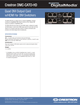
The diagram below shows a DM-RMC-100 in a classroom application.
DM-RMC-100 in a Classroom Application
For more information on this and other DM-RMC-100 applications, refer
to the latest revision of the Crestron DigitalMedia Design Guide
(Doc. 4789).
Operations & Installation Guide – DOC. 6743-1F Room Controller, CAT: DM-RMC-100 • 5

DigitalMedia™ Room Controller, CAT Crestron DM-RMC-100
Specifications
Specifications for the DM-RMC-100 are listed in the following table.
DM-RMC-100 Specifications
SPECIFICATION DETAILS
Video
Input Signal Type DM CAT (DigitalMedia over
twisted-pair copper wire)
Output Signal Types HDMI, DVI
1
Formats HDMI with Deep Color & 3D, DVI,
HDCP content protection support
Input Resolutions
Progressive 640 x 480 @ 60 Hz
720 x 480 @ 60 Hz (480p)
720 x 576 @ 50 Hz (576p)
800 x 600 @ 60 Hz
848 x 480 @ 60 Hz
852 x 480 @ 60 Hz
854 x 480 @ 60 Hz
1024 x 768 @ 60 Hz
1024 x 852 @ 60 Hz
1024 x 1024 @ 60 Hz
1280 x 720 @ 50 Hz (720p50)
1280 x 720 @ 60 Hz (720p60)
1280 x 768 @ 60 Hz
1280 x 800 @ 60 Hz
1280 x 960 @ 60 Hz
1280 x 1024 @ 60 Hz
1360 x 768 @ 60 Hz
1365 x 1024 @ 60 Hz
1366 x 768 @ 60 Hz
1400 x 1050 @ 60 Hz
1440 x 900 @ 60 Hz
1600 x 900 @ 60 Hz
1600 x 1200 @ 60 Hz
1680 x 1050 @ 60 Hz
(Continued on following page)
6 • Room Controller, CAT: DM-RMC-100 Operations & Installation Guide – DOC. 6743-1F

Crestron DM-RMC-100 DigitalMedia™ Room Controller, CAT
DM-RMC-100 Specifications (Continued)
SPECIFICATION DETAILS
Video
Input Resolutions
Progressive
(Continued)
1920 x 1080 @ 24 Hz (1080p24)
1920 x 1080 @ 25 Hz (1080p25)
1920 x 1080 @ 50 Hz (1080p50)
1920 x 1080 @ 60 Hz (1080p60)
1920 x 1200 @ 60 Hz
2048 x 1080 @ 24 Hz
2048 x 1152 @ 60 Hz
plus any other resolution allowed
by HDMI up to 165 MHz pixel
clock
Interlaced 720 x 480 @ 30 Hz (480i)
720 x 576 @ 25 Hz (576i)
1920 x 1080 @ 25 Hz (1080i25)
1920 x 1080 @ 30 Hz (1080i30)
plus any other resolution allowed
by HDMI up to 165 MHz pixel
clock
Output Resolutions Matched to input
Audio
Input Signal Type DM CAT
Output Signal Type HDMI
Formats Dolby
®
Digital, Dolby Digital EX,
Dolby Digital Plus, Dolby True HD,
DTS
®
, DTS-ES, DTS 96/24, DTS-
HD High Res, DTS HD Master
Audio™, up to 8ch PCM
Communications
DigitalMedia DM CAT, DMNet, HDCP
management, EDID format
management, CEC
(Continued on following page)
Operations & Installation Guide – DOC. 6743-1F Room Controller, CAT: DM-RMC-100 • 7

DigitalMedia™ Room Controller, CAT Crestron DM-RMC-100
DM-RMC-100 Specifications (Continued)
SPECIFICATION DETAILS
Communications
(Continued)
Ethernet 10BASE-T/100BASE-TX,
auto-switching, auto-negotiating,
auto-discovery, full/half duplex,
TCP/IP, UDP/IP, CIP, DHCP,
RSTP
USB Supports USB HID class devices
Power Requirements
DMNet Power Usage 6 Watts
(0.25 Amps @ 24 Volts DC)
Minimum 2-Series Control
System Update File
2, 3
Version 4.001.1040 or later
Environmental
Temperature 41º to 104º F (5º to 40º C)
Humidity 10% to 90% RH
(non-condensing)
Heat Dissipation 21 BTU/Hr
Enclosure
Chassis Metal, matte black finish
Mounting Surface mount
(mounting bracket included)
Dimensions
Height 4.54 in (116 mm)
Width 5.15 in (131 mm)
Depth 1.41 in (36 mm)
Weight 14 oz (392 g)
(Continued on following page)
8 • Room Controller, CAT: DM-RMC-100 Operations & Installation Guide – DOC. 6743-1F

Crestron DM-RMC-100 DigitalMedia™ Room Controller, CAT
DM-RMC-100 Specifications (Continued)
SPECIFICATION DETAILS
Available Accessories
CBL-HD Crestron Certified HDMI Interface
Cable
CBL-HD-DVI Crestron Certified HDMI to DVI
Interface Cable
CNSP-XX Custom Serial Interface Cable
CNXRMCS Current Sensor
DM-CBL DigitalMedia Cable
DM-CONN DigitalMedia Cable Connector
DM-DR DigitalMedia Repeater
IRP2 IR Emitter Probe
MP-WP140 Media Presentation Wall Plate –
DVI with Mini-TRS Stereo Audio
MP-WP152 Media Presentation Wall Plate –
HDMI
MP-WP185 Media Presentation Wall Plate -
Crestron DigitalMedia CAT with
DMNet
1. HDMI requires an appropriate adapter or interface cable to accommodate a DVI
signal. CBL-HD-DVI interface cable available separately.
2. The latest software versions can be obtained from the Crestron Web site. Refer to
the NOTE following these footnotes.
3. Crestron 2-Series control systems include the AV2 and PRO2. Consult the latest
Crestron Product Catalog for a complete list of 2-Series control systems.
NOTE: Crestron software and any files on the Web site are for
authorized Crestron dealers and Crestron Authorized Independent
Programmers (CAIP) only. New users may be required to register to
obtain access to certain areas of the site (including the FTP site).
Operations & Installation Guide – DOC. 6743-1F Room Controller, CAT: DM-RMC-100 • 9

DigitalMedia™ Room Controller, CAT Crestron DM-RMC-100
Physical Description
This section provides information on the connections, controls and
indicators available on your DM-RMC-100.
DM-RMC-100 Physical View (Front)
10 • Room Controller, CAT: DM-RMC-100 Operations & Installation Guide – DOC. 6743-1F

Crestron DM-RMC-100 DigitalMedia™ Room Controller, CAT
DM-RMC-100 Physical View (Back)
Operations & Installation Guide – DOC. 6743-1F Room Controller, CAT: DM-RMC-100 • 11

DigitalMedia™ Room Controller, CAT Crestron DM-RMC-100
DM-RMC-100 Overall Dimensions (Front View)
1
2
3
4
5
5.15 in
(131 mm)
4.54 in
(116 mm)
DM-RMC-100 Overall Dimensions (Bottom View)
11109876
1.41 in
(36 mm)
12 • Room Controller, CAT: DM-RMC-100 Operations & Installation Guide – DOC. 6743-1F

Crestron DM-RMC-100 DigitalMedia™ Room Controller, CAT
DM-RMC-100 Overall Dimensions (Rear View)
Connectors, Controls & Indicators
# CONNECTORS
1
,
CONTROLS &
INDICATORS
DESCRIPTION
1 PWR LED (1) Green LED, indicates
operating power supplied via
DMNet
2 DM LINK LED (1) Green LED, indicates
connection to an upstream DM
device
(Continued on following page)
Operations & Installation Guide – DOC. 6743-1F Room Controller, CAT: DM-RMC-100 • 13

DigitalMedia™ Room Controller, CAT Crestron DM-RMC-100
Connectors, Controls & Indicators (Continued)
# CONNECTORS
1
,
CONTROLS &
INDICATORS
DESCRIPTION
3 VIDEO LED (1) Red/green dual color LED,
indicates video signal presence
and lock status:
Red – indicates no video
Green – indicates the device is
receiving video
Blinking Red/Green –
indicates errors in the video
stream
4 CNTRL LED (1) Red/green dual color LED,
indicates Ethernet connection
and control system
communication status:
Red – indicates no Ethernet
link
Green – indicates Ethernet link
and connection to control
system
Blinking Red/Green –
indicates Ethernet link but no
connection to control system
Blinking Green - The LED
goes out momentarily every
time a control command is sent
or received (i.e. IR, RS-232,
Relay, Sens)
5 SETUP (LED and
Button)
(1) Red LED and (1) miniature
recessed push button, for
Ethernet auto-discovery and
default IP address
(Continued on following page)
14 • Room Controller, CAT: DM-RMC-100 Operations & Installation Guide – DOC. 6743-1F

Crestron DM-RMC-100 DigitalMedia™ Room Controller, CAT
Connectors, Controls & Indicators (Continued)
# CONNECTORS
1
,
CONTROLS &
INDICATORS
DESCRIPTION
6 SENS
(1) 2-pin 3.5 mm detachable
terminal block;
Digital/contact closure sensing
input;
Rated for 0-24 Volts DC,
referenced to ground;
Input impedance: 2.2k ohms
pulled up to 5 Volts DC;
Logic threshold: 2.5 Volts DC
nominal with 1 Volt hysteresis
band
7 HDMI
(1) 19-pin Type A HDMI
female;
HDMI digital video/audio output
Also supports DVI
2
8 USB
(1) USB Type A female;
USB 1.1 host port for
connection of a mouse,
keyboard or other USB
HID-compliant device
14 RELAY (1-2)
(1) 4-pin 3.5 mm detachable
terminal block comprising two
normally open, isolated relays;
Rated 1 Amp, 30 Volts AC/DC;
MOV arc suppression across
contacts
15 COM
(1) 5-pin 3.5 mm detachable
terminal block, bidirectional
RS-232 port;
Up to 115.2k baud, hardware
and software handshaking
support
(Continued on following page)
Operations & Installation Guide – DOC. 6743-1F Room Controller, CAT: DM-RMC-100 • 15

DigitalMedia™ Room Controller, CAT Crestron DM-RMC-100
Connectors, Controls & Indicators (Continued)
# CONNECTORS
1
,
CONTROLS &
INDICATORS
DESCRIPTION
16 IR (1-2)
(1) 4-pin 3.5 mm detachable
terminal block comprising
two IR/Serial ports;
IR output up to 1.1 MHz;
1-way serial TTL/RS-232
(0-5 Volts) up to 19200 baud
3
12 DM INPUT
4, 5
(1) DM CAT input composed of
two 8-pin RJ-45 female,
shielded;
Connects to DM CAT output of
a DM switcher, transmitter, or
other DM device via DM-CBL
cable
6
13 LAN
4
Green
LED
Yellow
LED
Pin 8
Pin 1
(1) 8-wire RJ-45 with two LED
indicators;
10BASE-T/100BASE-TX
Ethernet port;
Green LED indicates link
status;
Yellow LED indicates Ethernet
activity
PIN SIGNAL PIN SIGNAL
1 TX + 5 N/C
2 TX - 6 RX -
3 RX + 7 N/C
4 N/C 8 N/C
14 24 A B G
7, 8
(1) 4-pin 3.5 mm detachable
terminal block, DMNet port;
Connects to DMNet port of a
DM switcher, transmitter, or
other DM device via DM-CBL
cable
6
16 • Room Controller, CAT: DM-RMC-100 Operations & Installation Guide – DOC. 6743-1F
/