Page is loading ...

VX7 User’s Guide
Copyright © November 2004 by LXE Inc.
All Rights Reserved
E-EQ-VX7OGWW-A
Note: This is the full User's Guide. Please download the LXEbook version of this
guide to the mobile device, not this one.

LANGUAGE: ENGLISH
Notices
Notice:
LXE Inc. reserves the right to make improvements or changes in the products described in this manual at any time
without notice. While reasonable efforts have been made in the preparation of this document to assure its
accuracy, LXE assumes no liability resulting from any errors or omissions in this document, or from the use of the
information contained herein. Further, LXE Incorporated, reserves the right to revise this publication and to make
changes to it from time to time without any obligation to notify any person or organization of such revision or
changes.
Copyright Notice:
This manual is copyrighted. All rights are reserved. This document may not, in whole or in part, be copied,
photocopied, reproduced, translated or reduced to any electronic medium or machine-readable form without prior
consent, in writing, from LXE Inc.
Copyright © 2004 by LXE Inc. An EMS Technologies Company.
125 Technology Parkway, Norcross, GA 30092 U.S.A. (770) 447-4224
Trademarks:
LXE® is a registered trademark of LXE Inc.
Microsoft, Windows and the Windows logo are registered trademarks of Microsoft Corporation in the United
States and/or other countries.
All other brand or product names are trademarks or registered trademarks of their respective companies or
organizations. When this manual is in PDF format: “Acrobat ® Reader Copyright © 1987-2001 Adobe Systems
Incorporated. All rights reserved. Adobe, the Adobe logo, Acrobat, and the Acrobat logo are trademarks of Adobe
Systems Incorporated.” applies.
!
The user is strongly cautioned to read Appendix B, “Regulatory Notices and Safety
Information”. Important safety cautions, warnings and regulatory information is contained in
Appendix B.

E-EQ-VX7OGWW-A VX7 User’s Guide
Table of Contents
THE VX7 VEHICLE MOUNT COMPUTER 1
Introduction ............................................................................................................... 1
Document Conventions ............................................................................................................2
Environmental Specifications...................................................................................................3
Quick Start................................................................................................................. 4
Components .............................................................................................................. 5
The Full-Screen Display ........................................................................................... 8
VX7 Control Panel..................................................................................................... 8
Microsoft Windows CE .NET Control Panel............................................................ 8
PCMCIA, ATA and SD Slots ..................................................................................... 8
The Keyboards .......................................................................................................... 9
The 95-key QWERTY Keyboard with Pointing Device ........................................................10
Key Maps .............................................................................................................................10
NumLock and the VX7.................................................................................................................. 10
CapsLock, Scroll Lock and the VX7 ............................................................................................. 10
Keyboard Backlight..............................................................................................................11
Pointing device.....................................................................................................................11
The 60-key QWERTY Keyboard ...........................................................................................12
Key Maps .............................................................................................................................12
Unused Key Functions .........................................................................................................12
NumLock and the VX7 ........................................................................................................13
Keyboard Backlight..............................................................................................................13
Keyboard LEDs....................................................................................................................13
CAPS LED..................................................................................................................................... 13
Secondary Keys LED..................................................................................................................... 14
Control Keys ........................................................................................................................15
General Windows CE .NET Keyboard Shortcuts...................................................................16
PS/2 Keyboard/Mouse............................................................................................................16
PS/2 Mouse ..........................................................................................................................16
Input Panel (Virtual Keyboard) ..............................................................................................17
Enabling the Input Panel ......................................................................................................18
Power Supply .......................................................................................................... 19
Uninterruptible Power Supply Battery Pack ..........................................................................19
Backup Battery .......................................................................................................................19
Getting Help............................................................................................................. 20
Manuals and Accessories ...................................................................................... 20

ii Table of Contents
VX7 User’s Guide E-EQ-VX7OGWW-A
Manuals...................................................................................................................................20
Accessories .............................................................................................................................20
INSTALLATION 23
Install Mounting Brackets ...................................................................................... 23
RAM Mount System...............................................................................................................24
Components..........................................................................................................................24
Torque Measurements ..........................................................................................................25
Procedure..............................................................................................................................25
Step 1 – Mount Vehicle RAM Mount Bracket .............................................................................. 25
Mounting Dimensions .....................................................................................................26
Step 2 – Attach RAM Mount Ball to the VX7............................................................................... 27
Step 3 – Assemble Optional Keyboard Brackets ........................................................................... 28
Step 4 – Attach VX7 and Bracket Assembly to RAM Mount ....................................................... 30
Completed Assembly..............................................................................................................32
U-Bracket Mount System .......................................................................................................33
Components..........................................................................................................................33
Mounting Positions ..............................................................................................................34
Torque Measurements ..........................................................................................................34
Procedure..............................................................................................................................35
Step 1 - Mount Bottom Mounting Bracket To Vehicle. ................................................................ 35
Mounting Dimensions .....................................................................................................35
Step 2 – Attach Rear Bracket VX7 ................................................................................................36
Step 3 – Attach VX7 Assembly To Bottom Mounting Bracket..................................................... 37
Step 4 – Assemble Optional Keyboard Brackets ........................................................................... 38
Step 5 – Complete Assembly......................................................................................................... 40
Completed Assembly..............................................................................................................41
Install Stylus Tether and Sleeve .............................................................................................42
Install/Remove Touchscreen Protective Film.........................................................................43
Remote LXE Keyboard Bracket Assembly............................................................................44
Remote Keyboard Mounting Dimensions............................................................................45
UPS Battery Pack Remote Mount ..........................................................................................46
UPS Battery Pack Remote Mounting Dimensions...............................................................46
Connect Keyboard .................................................................................................. 47
LXE Keyboard........................................................................................................................47
PS/2 Keyboard and Mouse .....................................................................................................48
Connect Antenna .................................................................................................... 49
Remote Vehicle Antenna Mount ............................................................................................49
Connect Serial Barcode Scanner .......................................................................... 50
Connect Serial Printer or PC.................................................................................. 52
Ethernet and USB Ports ......................................................................................... 53
USB Mouse.............................................................................................................................54
Connect External Headset...................................................................................... 55

Table of Contents iii
E-EQ-VX7OGWW-A VX7 User’s Guide
Connect Power Cable and Optional UPS Battery Pack ....................................... 56
External Power Supply, Optional........................................................................... 57
Vehicle 12-80VDC Power Connection ................................................................... 58
Power Adapter Cable.............................................................................................. 64
Fuse Replacement for the VX7 .............................................................................. 65
OPERATION 67
Powering On/Off...................................................................................................... 67
Keyboard Backlight ................................................................................................ 68
95 Key Keyboard....................................................................................................................68
60 Key Keyboard....................................................................................................................68
PS/2 Keyboard ........................................................................................................................68
Display and Touchscreen....................................................................................... 69
Adjusting Screen Display .......................................................................................................69
Cleaning the Display ..............................................................................................................69
Disabling the Touchscreen .....................................................................................................69
Calibrating the Touchscreen...................................................................................................70
Touchscreen Protective Film ..................................................................................................70
Touchscreen and Mouse .........................................................................................................70
Adjust Speaker Volume.......................................................................................... 71
Microsoft Windows CE .NET Event Sounds .........................................................................71
Power Management ................................................................................................ 71
Laser Barcode Scanner Warnings......................................................................... 72
Enter Data................................................................................................................ 72
Keyboard Entry.......................................................................................................................73
Touchscreen Entry..................................................................................................................73
Right Click ...........................................................................................................................73
Scanner Entry..........................................................................................................................74
Aiming the Barcode Scanner................................................................................................74
Distance from Label .............................................................................................................74
Successful Scan ....................................................................................................................74
Unsuccessful Scan................................................................................................................74
APPENDIX A KEY MAPS 75
95-key Keypad with Pointing Device ..................................................................... 75
Key Map 101-Key Equivalencies...........................................................................................75
60-key Standard Keypad ........................................................................................ 76
Key Map 101-Key Equivalencies...........................................................................................76

iv Table of Contents
VX7 User’s Guide E-EQ-VX7OGWW-A
APPENDIX B REGULATORY NOTICES AND SAFETY INFORMATION 81
INDEX 91
Illustrations
Figure 1 VX7 Components, Top View ................................................................................................................5
Figure 2 VX7 Components, Front View..............................................................................................................5
Figure 3 VX7 Components, Bottom View...........................................................................................................6
Figure 4 VX7 Components, Back View ..............................................................................................................6
Figure 5 VX7 Control Panel ................................................................................................................................6
Figure 6 VX7 Access Panel .................................................................................................................................7
Figure 7 The VX7 PCMCIA, CF and SD Slots ...................................................................................................8
Figure 8 The LXE Keyboards with Cable ...........................................................................................................9
Figure 9 The 95-key QWERTY Keyboard ........................................................................................................10
Figure 10 The 60-key QWERTY Keyboard ......................................................................................................12
Figure 11 Keyboard LEDs.................................................................................................................................13
Figure 12 The CapsLock Key ............................................................................................................................13
Figure 13 The Secondary Key ...........................................................................................................................14
Figure 14 The Keyboard Display Controls ........................................................................................................15
Figure 15 Small and Large Virtual Keyboards ..................................................................................................17
Figure 16 Input Panel Properties........................................................................................................................18
Figure 17 Connect Vehicle RAM Mount Bracket to Vehicle............................................................................25
Figure 18 VX7 RAM Bracket - Mounting Dimensions (Not To Scale) ............................................................26
Figure 19 Attach RAM Mount Ball to VX7 ......................................................................................................27
Figure 20 Attach Keyboard Mounting Bracket..................................................................................................28
Figure 21 Attach Keyboard to Mounting Plate..................................................................................................29
Figure 22 RAM Assembly without Keyboard ...................................................................................................30
Figure 23 RAM Assembly with Keyboard ........................................................................................................31
Figure 24 Completed RAM Mount Assembly ...................................................................................................32
Figure 25 Suggested Mounting Positions ..........................................................................................................34
Figure 26 Connect Bottom Bracket to Vehicle..................................................................................................35
Figure 27 VX7 Bracket - Mounting Dimensions (Not To Scale) ......................................................................35
Figure 28 Attach Rear Bracket to VX7..............................................................................................................36
Figure 29 Attach VX7 Assembly to Bottom Bracket ........................................................................................37
Figure 30 Attach Rear Bracket and Keyboard to VX7 ......................................................................................38
Figure 31 Attach Keyboard Assembly to VX7..................................................................................................39
Figure 32 Integrated UPS Battery Pack Mount .................................................................................................40
Figure 33 VX7 in Vehicle Bracket ....................................................................................................................41
Figure 34 Stylus Tether Mounting Holes...........................................................................................................42
Figure 35 Tethered Stylus, Typical Installation.................................................................................................42
Figure 36 VX7 Touchscreen Protective Film ....................................................................................................43
Figure 37 Remote Keyboard Bracket Assembly................................................................................................44
Figure 38 Remote Keyboard - Mounting Dimensions.......................................................................................45
Figure 39 Remote UPS Battery Pack Mount .....................................................................................................46
Figure 40 UPS Battery Pack Remote Mounting Dimensions ............................................................................46
Figure 41 Keyboard Connection Location and Keyboard .................................................................................47
Figure 42 VX7 PS/2 Keyboard/Mouse Dongle Cable .......................................................................................48
Figure 43 Connect 2.4GHz Antenna..................................................................................................................49

Table of Contents v
E-EQ-VX7OGWW-A VX7 User’s Guide
Figure 44 Connect Serial Scanner Cable ...........................................................................................................50
Figure 45 VX7 with Generic Barcode Scanner Attached ..................................................................................51
Figure 46 Generic Barcode Scanner ..................................................................................................................51
Figure 47 Connect Serial Cable to COM3 .........................................................................................................52
Figure 48 VX7 Ethernet/USB-H/USB-C Dongle Cables ..................................................................................53
Figure 49 Connect Ethernet/USB Dongle Cable ...............................................................................................53
Figure 50 Connect USB Device to Dongle Cable..............................................................................................54
Figure 51 Connect Ethernet Cable to Adapter Cable.........................................................................................54
Figure 52 Connect External Headset .................................................................................................................55
Figure 53 Connect Power Cable to VX7 ...........................................................................................................56
Figure 54 Optional Power Configuration ..........................................................................................................57
Figure 55 Vehicle Power Connection Cable (Fuse Not Shown)........................................................................58
Figure 56 Connecting the Power Cable to the Vehicle......................................................................................58
Figure 57 Vehicle Connection Wiring Color Codes..........................................................................................59
Figure 58 Direct Connection (No UPS Battery Pack) .......................................................................................60
Figure 59 Integrated Mount UPS Battery Pack Connection ..............................................................................61
Figure 60 Remote Mount UPS Battery Pack Connection..................................................................................62
Figure 61 Power Adapter Cable, VX1/2/4 to VX6............................................................................................64
Figure 62 Fuse Replacement..............................................................................................................................65
Figure 63 The VX7 Power Switch.....................................................................................................................67
Figure 64 Touchscreen Calibration, Calibration Targets...................................................................................70
Figure 65 Caution Labels Class II Scanner........................................................................................................72
Figure 66 Caution Labels Class IIIA Scanner ...................................................................................................72
Figure 67 Scan Beam.........................................................................................................................................74
Figure 68 95-Key LXE QWERTY Keyboard....................................................................................................75
Figure 69 60-Key LXE QWERTY Keyboard....................................................................................................76

vi Table of Contents
VX7 User’s Guide E-EQ-VX7OGWW-A

E-EQ-VX7OGWW-A VX7 User’s Guide
The VX7 Vehicle Mount Computer
Introduction
The VX7 Vehicle Mount Computer (VMC) is a rugged, vehicle-mounted, Microsoft
®
Windows
®
CE .NET equipped computer. The VX7 is capable of wireless data communications from a fork-
lift truck or any properly configured vehicle. The unit uses a PCMCIA radio (spread spectrum
2.4GHz) for wireless data communications.
The VX7 is a tablet-style computer and features a SVGA color TFT display. The touch-screen
display supports graphic features and Microsoft Windows CE .NET icons that the Windows CE
.NET operating system supports. An illuminated keyboard is available to facilitate use in dimly lit
areas.
The VX7 provides the power and functionality of a desktop computer in a vehicle mounted unit,
with a wide range of options:
• 400MHz Intel
®
PXA255 CPU
• 64 or 128MB of DRAM
• Wireless LAN radios with single or dual antenna option
• Ethernet port
• USB Host and Client ports
• Choice of indoor or outdoor full screen display
• Available touch screen protective film
• Available Uninterruptible Power Supply (UPS) Battery Pack
• Extended temperature version
Note: The “VX7 Reference Guide” contains VX7 technical information and advanced
functions.

2 Introduction
VX7 User’s Guide E-EQ-VX7OGWW-A
Document Conventions
This reference guide uses the following document conventions:
ALL CAPS All caps are used to represent disk directories, file names, and application
names.
Menu|Choice Rather than use the phrase “choose the Save command from the File menu”,
this manual uses the convention “choose File|Save”.
“Quotes” Indicates the title of a book, chapter or a section within a chapter (for
example, “Document Conventions”).
< > Indicates a key on the keyboard (for example, <Enter> ).
Indicates a reference to other documentation.
Differences in operation or commands due to radio type.
ATTENTION
Keyword that indicates vital or pivotal information to follow.
!
Attention symbol that indicates vital or pivotal information to follow. Also,
when marked on product, means to refer to the manual or operator’s guide.
International fuse replacement symbol. When marked on the product, the
label includes fuse ratings in volts (v) and amperes (a) for the product.
Note: Keyword that indicates immediately relevant information.
Caution
!
Keyword that indicates a potentially hazardous situation, which, if not
avoided, may result in minor or moderate injury.
WARNING
!
Keyword that indicates a potentially hazardous situation, which, if not
avoided, could result in death or serious injury.
DANGER
!
Keyword that indicates an imminent hazardous situation, which, if not
avoided, will result in death or serious injury.

Introduction 3
E-EQ-VX7OGWW-A VX7 User’s Guide
Environmental Specifications
Feature Specification
Operating Temperature
Standard version -4°F to 122°F (-20°C to 50°C) [non-condensing]
Extended Temperature version -22º to 122º F (-30ºC to 50ºC [condensing]
Storage Temperature
Standard version -22°F to 140°F (-30°C to 60°C) [non-condensing]
Extended Temperature version -22°F to 140°F (-30°C to 60°C) [condensing]
Water, Sand Dust IP66 per IEC60529
Operating Humidity
Standard version Up to 90% non-condensing at 104°F (40°C)
Extended Temperature version 100%
Vibration Based on MIL Std 810F
ESD 15 kV

4 Quick Start
VX7 User’s Guide E-EQ-VX7OGWW-A
Quick Start
This section’s instructions are based on the assumption that your new system is pre-configured
and requires only accessory installation (e.g. antenna, external keyboard and/or barcode scanner)
and a power source.
Use this guide as you would any other source book -- reading portions to learn about the VX7,
and then referring to it when you need more information about a particular subject. This guide
takes you through installation and operation of the LXE VX7.
In general, the sequence of events is:
1. Install Vehicle Mounting Bracket (and keyboard mounting bracket) on vehicle.
2. Secure VX7 in Mounting Bracket Assembly.
3. Connect vehicle power source to VX7 power cable.
4. Connect power cable to the VX7. The power cable can also be connected to a UPS
battery pack, which is then connected to the VX7.
5. Connect accessories to VX7, e.g. scanner, antenna, keyboard.
6. Secure all cables to the VX7 with the Strain Relief Cable Clamps.
7. Turn the VX7 on.
The VX7 and its keyboard should be mounted in an area in the vehicle where it:
• Does not obstruct the vehicle driver’s vision or safe vehicle operation.
• Can be easily accessed by anyone seated in the driver’s seat.

Components 5
E-EQ-VX7OGWW-A VX7 User’s Guide
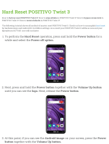
Components
2
1
1. Access Panel Cover (See
Following Illustrations for
Detail)
2. Antenna Connectors or
Hole Plugs
Figure 1 VX7 Components, Top View
V
X5
2
1
1. Speakers
2. Control Panel
(See Following
Illustrations for Detail)
Figure 2 VX7 Components, Front View

6 Components
VX7 User’s Guide E-EQ-VX7OGWW-A
T10A, 125V
INPUT:
12-80VDC
6A 72W
AUDIO
ETHERNET /
USB
KEYBOARD /
MOUSE
COM2COM1 / SCANNER
N107
REFER TO
MANUAL
IP66
LISTED
I.T.E.
E-130794
C
PRODUCT OF U.S.A. U.S. PATENT 5862393
US
U
L
®
THIS DEVICE COMPLIES WITH PART 15 OF THE FCC RULES.
OPERATION IS SUBJECT TO THE FOLLOWING TWO
CONDITIONS: (1) THIS DEVICE MAY NOT CAUSE HARMFUL
INTERFERENCE, AND (2) THIS DEVICE MU ST ACCEPT ANY
INTERFERENC E RECEIVED, INCLUD ING INTERFERENCE
THAT MAY CAUSE UNDESIRED OPERATION.
This Class A digital apparatus complies with
Canadian ICE-003.
Cet appareilnum de la ClasseA est
confirme l
érique
orme NMB-003 du Canadaà n
CAUTION: For continues protection against risk of fire,
replace only with same type and rating of fuse.
ATTENTION: Pour ne pas compromette la preotection
contre les risques d'incendie, remplacer par un fusible
de mmes types de mmes caractristques nominales.êêé
6
7
54
3
2
1
1. COM1/Scanner
Connector
2. COM3 Connector
3. Keyboard/Mouse
Connector
4. Ethernet/USB Cable
Connector (USB-Host and
USB-Client)
5. Fuse
6. Audio Connector
7. Power Cable Connector
Figure 3 VX7 Components, Bottom View
Note: COM1 is configured with Pin 9 +5V. COM3 is labeled “COM2/3” and is configured
with Pin 9 RI. Please see the VX7 Reference Guide for details.
3
2
1
1. Antenna Connectors
2. Bracket Mounting Area
3. Strain Relief Bracket and
Screws
Figure 4 VX7 Components, Back View
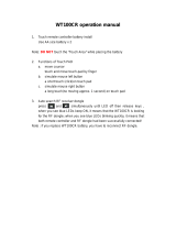
1
2
3
4
1. Power LED
2. Power Switch
3. Brightness Increase
4. Brightness
Decrease
Figure 5 VX7 Control Panel

Components 7
E-EQ-VX7OGWW-A VX7 User’s Guide
SD CF ATA
PCMCIA A
PCMCIA B
21
3
1. SD Memory Card
Slot
2. Compact Flash ATA
Hard Drive
3. PCMCIA Slots
Figure 6 VX7 Access Panel
Note: The tethered access panel cover is not shown in the illustration above.

8 The Full-Screen Display
VX7 User’s Guide E-EQ-VX7OGWW-A
The Full-Screen Display
The VX7 Display is a TFT color unit capable of supporting SVGA graphics modes. The
resolution is 800 x 600 pixels.
VX7 Control Panel
The VX7 control panel contains the status LED, power button and display brightness adjustment
buttons. Please refer to the “Operation” section, later in this manual, for details on the VX7
Control Panel.
Microsoft Windows CE .NET Control Panel
The Microsoft Windows CE .NET Control Panel provides standard Windows CE .NET options
for configuring the VX7, such as:
• Sound volume
• Display configuration
Please consult your System Administrator or refer to commercially available
Microsoft Windows CE .NET user guides or the on-line Help application for these
standard Windows CE .NET configuration options.
PCMCIA, ATA and SD Slots
The VX7 has two PCMCIA slots. These slots are intended for use with Type I or II cards, such as
LXE’s 2.4GHz Spread Spectrum radios. These slots are hot swappable per PCMCIA
specifications.
The Compact Flash (CF) slot contains the Compact Flash ATA hard drive. This drive contains
the Operating System and the Documents and Settings. The VX7 does not operate without this
card installed. The CF card is not hot swappable.
One Secure Digital (SD) slot is provided for SD memory cards. The SD card is hot swappable.
SD CF ATA
PCMCIA A
PCMCIA B
21
3
1. SD Memory Card Slot
2. Compact Flash Hard Drive
3. PCMCIA Slots
Figure 7 The VX7 PCMCIA, CF and SD Slots
Please see the “VX7 Reference Guide” for more details on the PCMCIA, CF and SD slots.

The Keyboards 9
E-EQ-VX7OGWW-A VX7 User’s Guide
The Keyboards
The following keyboard options are available for the VX7:
• LXE 95-key QWERTY keyboard with integrated pointing device – a customized
rugged keyboard connected to the VX7 via a watertight connector.
• LXE 60-key QWERTY keyboard – a customized rugged keyboard connected to the
VX7 via a watertight connector
• A standard PS/2 keyboard via an adapter cable attached to the “Keyboard/MOUSE”
port on the VX7. The adapter cable also provides a connector for a PS/2 mouse.
• A software keyboard, or virtual keyboard, can be displayed on the touch screen. The
virtual keyboard can be used in place of, or in addition to, a physical keyboard.
For more details on each keyboard type, please refer to the appropriate section later in this
chapter.
95 key with Integrated Pointing Device
CAPS
2nd
9
8
7
/
-+
4
5
6
INS
BKSP
CTRL
#
E
*
I
!
Q
@
W
O
(
P
)
R
$
T
%
U
&
Y
^
=
}{
PgUp
ENTER
SHIFT
:
D
;
F
"
G
'
H
.
K
123
L
?
S
\
A
|
J
’
]>[
Home
PgDn END
ALT SP
~
B
CVXZ
DEL
0
M
_
N
´
<
.
CAPS
BREAK
R/S
BKLT
ESC 2ND
F1
F2
F3 F4 F5 F6
F7
F8
F9
F10
60 key
Figure 8 The LXE Keyboards with Cable

10 The Keyboards
VX7 User’s Guide E-EQ-VX7OGWW-A
The 95-key QWERTY Keyboard with Pointing Device
Designed for ease of use with the Windows CE .NET operating system, the 95-key keyboard with
pointing device connects via a cable to the keyboard port on the VX7. Additional Windows keys
(the Windows logo key and the Application key) and an integrated pointing device are provided
for use with Windows CE .NET operating system.
RL
1
!
2
Esc
Print
SysRq
Screen
Scroll
Lock
Fn
Pause
Break
F2 F3 F4 F5 F6 F7 F8 F9 F10 F11 F12F1
3
#@
4
$
5
%
6
^
0
)
8
*
7
&
-
_
9
(
=
+
BackSpace
Num
Lock
/*
=
~
`
Q W E R T UY IO
Tab
A S D F G JHK
Z X C V BMN
.
>
,
<
/
?
L
;
:
'
"
P
]
}
\
|
[
{
8
PgUp
9
Home
7
2
PgDn
3
End
1
5
6
4
+
Ins
0
Del
.
CtrlAlt
Enter
Shift
Enter
Ctrl
Alt
Shift
Caps
Lock
Figure 9 The 95-key QWERTY Keyboard
Note: The 2
nd
key function is available on the 60-key keyboard only.
Key Maps
The 95-key keyboard supports all 104 keyboard functions (101 keyboard standard plus Windows
keys) and includes an integrated pointing device and left and right mouse buttons. However,
because the keyboard only has 95 keys, all functions are not visible (or printed on the keyboard).
Therefore the VX7 keyboard supports what is called hidden keys -- keys that are accessible but
not visible on the keyboard.
The hidden keys supported by the VX7 are listed in Appendix A, “Key Maps”.
NumLock and the VX7
For the 95-key keyboard, the NumLock key and the numeric keys are backlit green when
NumLock is off. When NumLock is on, the backlight for the NumLock key and the numeric keys
are amber.
The default value for NumLock is On.
The warmboot behavior of NumLock can be configured. Please refer to the “VX7 Reference
Guide” for more information.
CapsLock, Scroll Lock and the VX7
For the 95-key keyboard, the CapsLock key is backlit green when CapsLock is off. When
CapsLock is on, the backlight for the CapsLock key is amber.
The Scroll Lock key is backlit green when Scroll Lock is off. When Scroll Lock is on, the
backlight for the Scroll Lock key is amber.
The default values for CapsLock and Scroll Lock are Off.

The Keyboards 11
E-EQ-VX7OGWW-A VX7 User’s Guide
Keyboard Backlight
The 95-key keyboard backlights each key with an LED. The keyboard backlight is
manually controlled using the “backlight” key in the upper right hand corner of the
keyboard. Pressing the backlight key cycles the keyboard backlight through the levels of
backlight intensity:
• Off
• Maximum intensity
• Medium intensity
• Low intensity.
Pointing device
The mouse pointer may not always be visible. Please see “Touchscreen and Mouse” later in this
manual for more details.

12 The Keyboards
VX7 User’s Guide E-EQ-VX7OGWW-A
The 60-key QWERTY Keyboard
The 60-key keyboard has 101 keyboard functions, including a numeric keyboard pad. Please refer
to Appendix A, “Key Maps”, for keypress combinations.
CAPS
2nd
9
8
7
/
-+
4
5
6
INS
BKSP
CTRL
#
E
*
I
!
Q
@
W
O
(
P
)
R
$
T
%
U
&
Y
^
=
}{
PgUp
ENTER
SHIFT
:
D
;
F
"
G
'
H
.
K
123
L
?
S
\
A
|
J
’
]>[
Home
PgDn END
ALT SP
~
B
CVXZ
DEL
0
M
_
N
´
<
.
CAPS
BREAK
R/S
BKLT
ESC 2ND
F1
F2
F3
F4 F5
F6
F7
F8
F9
F10
Figure 10 The 60-key QWERTY Keyboard
Key Maps
The 60-key keyboard supports all 101 keyboard functions. However, because the keyboard only
has 60 keys, all functions are not visible (or printed on the keyboard). Therefore the VX7
keyboard supports what is called hidden keys -- keys that are accessible but not visible on the
keyboard.
The hidden keys supported by the VX7 are listed in Appendix A, “Key Maps”.
Unused Key Functions
There are several key functions on the 60-key keyboard that are not used on the VX7. These
include:
• <2nd> <F3> – The Resume/Suspend function is not used, as the VX7 does not
support these power management modes.
• <2nd> <F4> and <2nd> <F5> – The Display Brightness functions are not used as
the display brightness is adjusted by the buttons on the VX7 control panel.
• <2nd> <F6> and <2nd> <F7> – The Contrast functions are not used as the contrast
is not adjustable on the TFT display on the VX7.
• <2nd> <F8> and <2nd> <F9> – The Volume control keys are not used as volume is
adjusted via the Microsoft Windows CE .NET Control Panel.
• <2nd> <F10> – Please see “Keyboard Backlight” later in this section for details on
toggling the keyboard backlight.
/