Page is loading ...

VX7User Guide
E-EQ-VX7OGWW-P
2010 Copyright© by LXE®, Inc, An EMS Technologies Company. All Rights
Reserved.

Notices
LXE Inc. reserves the right to make improvements or changes to published VX7 information at any time without notice. While
reasonable efforts have been made in the preparation of this publication to assure its accuracy, LXE assumes no liability
resulting from any errors or omissions in this publication, or from the use of the information contained herein. Further, LXE
Incorporated, reserves the right to revise this publication and to make changes to it from time to time without any obligation to
notify any person or organization of such revision or changes.
Trademarks
Copyright © 2010 by LXE Inc., An EMS Technologies Company, 125 Technology Parkway, Norcross, GA 30092 U.S.A. (770)
447-4224
LXE® and Spire® are registered trademarks of LXE Inc.
RFTerm® is a registered trademark of EMS Technologies, Norcross, GA.
Microsoft®, ActiveSync®, MSN, Outlook®, Windows®, Windows Mobile®, the Windows logo, and Windows Media are
either registered trademarks or trademarks of Microsoft Corporation in the United States and/or other countries.
Intel and Intel XScale are trademarks or registered trademarks of Intel Corporation or its subsidiaries in the United States and
other countries.
Summit Data Communications, Inc. Summit Data Communications, the Summit logo, and “The Pinnacle of Performance” are
trademarks of Summit Data Communications, Inc.
The Cisco Square Bridge logo is a trademark of Cisco Systems, Inc.; Aironet, Cisco and Cisco Systems are registered
trademarks of Cisco Systems, Inc. and/or its affiliates in the United States and certain other countries.
Java® and Java-based trademarks and logos are trademarks or registered trademarks of Sun Microsystems, Inc. in the U.S.
or other countries, and are used under license.
The Bluetooth® word mark and logos are owned by the Bluetooth SIG, Inc. and any use of such marks by LXE, Inc. is under
license.
PowerScan is a registered trademark of Datalogic Scanning, Inc., located in Eugene, OR.
Symbol® is a registered trademark of Symbol Technologies. MOTOROLA® and the Stylized M Logo are registered
trademarks of Motorola®, Inc.
Hand Held® is a registered trademark of Hand Held Products, Inc., located in Skaneateles Falls, NY.
Wavelink®, the Wavelink logo and tagline, Wavelink Studio™, Avalanche Management Console™, Mobile Manager™, and
Mobile Manager Enterprise™ are trademarks of Wavelink Corporation, Kirkland.
RAM® and RAM Mount™ are both trademarks of National Products Inc., 1205 S. Orr Street, Seattle, WA 98108.
When any part of this publication is in PDF format: “Acrobat ® Reader Copyright © 2010 Adobe Systems Incorporated. All
rights reserved. Adobe, the Adobe logo, Acrobat, and the Acrobat logo are trademarks of Adobe Systems Incorporated”
applies.
Other product names mentioned within this publication may be trademarks or registered trademarks of other companies.

Table of Contents
Set Up A New VX7 1
Hardware Setup 1
Software Setup 1
Components 3
Top View 3
Front View 3
Bottom View 4
Back View 5
Control Panel 6
Access Panel 6
Tapping the Touchscreen with a Stylus 7
Backlights and Indicators 8
System Status LED 8
Keyboard LEDs 8
CAPS LED (60 key keyboard) 8
Secondary Keys LED (60 key keyboard) 8
Connecting Cables to the VX7 9
Connect Cable- USB Client 9
USB-C Cable Assembly 9
Connect Cable - Serial 10
Connecting to USB and Optional Ethernet Ports 11
Connecting an AC/DC Power Supply 12
Connecting Vehicle Power 13
Vehicle 12-80 VDC Power Connection Cable 13
How To: Connect Vehicle 12-80VDC Connection 15
How To: Connect VX7 without a UPS Battery Pack 16
How To: Connect VX7 to an Integrated Mount UPS Battery Pack 17
How To: Connect VX7 to a Remotely Mounted UPS Battery Pack 18
Power Adapter Cable 20
Uninterruptible Power Supply Battery Pack 21
UPS Battery Pack Remote Mounting 21
UPS Battery Pack Remote Mounting Dimensions 22
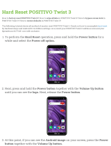
Connecting the Headset Cable 23
Adjust Headset / Microphone and Secure Cable 24
Connecting a Tethered Scanner 25
Attach Stylus Tether and Sleeve 26
Set Date and Time Zone 27
E-EQ-VX7OGWW-P [ i ] VX7 User Guide

Table of Contents
Grab Time Utility 27
Autolaunch Time-Sync 27
Using the Input Panel / Virtual Keyboard 28
Adjust Speaker Volume 29
Using the Control Panel 29
Touchscreen 30
Calibrating the Touchscreen 30
Adjusting the Display Backlight Timer 30
Apply the Touchscreen Protective Film 30
Cleaning the Touchscreen and Scanner Aperture 31
Setup Terminal Emulation Parameters 31
Using the AppLock Switchpad 32
Using the Keypad 32
Using the Touchscreen 32
Connecting to Bluetooth Devices 33
Taskbar Connection Indicator 33
Reboot 34
Warm Boot 34
Cold Boot 34
Troubleshooting 34
Regulatory Notices and Safety Information 35
Class A Digital Device 35
RF Notices 36
RF Safety Notice 36
Lithium Battery Safety Statement 37
Vehicle Power Supply Connection Safety Statement 38
Revision History 38
Index 39
E-EQ-VX7OGWW-P [ ii ] VX7 User Guide

Set Up A New VX7
Note: LXE recommends that installation or removal of accessories be performed on a clean, well-lit surface. When
necessary, protect the work surface, the VX7, and components from electrostatic discharge.
While the VX7 is in a Hazardous Location DO NOT:
l Connect an external power source to the VX7.
l Connect a USB device or audio jack to the VX7.
l Connect a tethered scanner to the VX7.
l Place the VX7 in a powered dock or cradle.
Hardware Setup
1. Connect accessories.
2. Connect cables.
3. Connect power cable.
4. Secure all cables to the VX7 with the Strain Relief Cable Clamps.
5. Press the Power key.
Software Setup
Prerequisite: Hardware setup is complete.
1. Calibrate Touch screen
2. Adjust Speaker Volume
3. Pair Bluetooth devices
4. Setup Wireless client parameters
5. Setup terminal emulation parameters
6. Save changed settings to the registry
7. Setup the LXE AppLock parameters
8. Set the LXE Scanner Wedge parameters
End User License Agreement (EULA)
When a new VX7 starts up a EULA is displayed on the touchscreen. It remains on the screen until the Accept or Decline button
is tapped with a stylus.
Tap the Accept button to accept the EULA terms and the VX7 continues the startup process. The EULA is not presented to the
user again.
Tap the Decline button to decline the EULA and the VX7 will reboot. It will continue to reboot until the Accept button is tapped
with the stylus.
E-EQ-VX7OGWW-P [ 1 ] VX7 User Guide

Software Setup
Note: The EULA will be presented after any operating system upgrade or re-installation, including language-specific
operating systems.
E-EQ-VX7OGWW-P [ 2 ] VX7 User Guide

Components
Components
Top View
1. Access Panel Cover
2. Antenna Connectors or Hole Plugs
Front View
1. Speakers
2. Control Panel
E-EQ-VX7OGWW-P [ 3 ] VX7 User Guide

Bottom View
Bottom View
1. COM1/Scanner Connector
2. COM3 Connector
3. Keyboard/Mouse Connector
4. Ethernet/USB Cable Connector (USB-Host and USB-Client)
5. Fuse
6. Audio Connector
7. Power Cable Connector
E-EQ-VX7OGWW-P [ 4 ] VX7 User Guide

Back View
Back View
1. Antenna Connectors
2. Bracket Mounting Area
3. Strain Relief Bracket and Screws
E-EQ-VX7OGWW-P [ 5 ] VX7 User Guide

Control Panel
Control Panel
1. Status / Power LED
2. Power Switch
3. Brightness Increase
4. Brightness Decrease
Access Panel
1. SD Memory Card Slot
2. Compact Flash Hard Drive
3. PCMCIA Slots
E-EQ-VX7OGWW-P [ 6 ] VX7 User Guide

Tapping the Touchscreen with a Stylus
Tapping the Touchscreen with a Stylus
Note: Always use the point of the stylus for tapping or making strokes on the touchscreen.
Never use an actual pen, pencil, or sharp/abrasive object to write on the touchscreen.
Hold the stylus as if it were a pen or pencil. Touch an element on the screen with the tip of the stylus then remove the stylus
from the screen.
Firmly press the stylus into the stylus holder when the stylus is not in use.
Using a stylus is similar to moving the mouse pointer then left-clicking icons on a desktop computer screen.
Using the stylus to tap icons on the touchscreen is the basic action that can:
l Open applications
l Choose menu commands
l Select options in dialog boxes or drop-down boxes
l Drag the slider in a scroll bar
l Select text by dragging the stylus across the text
l Place the cursor in a text box prior to typing in data
l Place the cursor in a text box prior to retrieving data using the scanner/imager or an input/output device connected to the
serial port.
A right-click can be simulated by touching the touchscreen with the stylus and holding it for a short time.
A stylus replacement kit is available.
E-EQ-VX7OGWW-P [ 7 ] VX7 User Guide

Backlights and Indicators
Backlights and Indicators
System Status LED
The LED above the power button indicates the status of the VX7.
l Off - The VX7 is Off.
l Green - Running on 12V – 80V power input
l Solid Yellow - Running on UPS battery, battery is not low on power
l Flashing Yellow - Running on UPS battery, battery is critically low.
Keyboard LEDs
The VX7 with 60 key keyboard has two keyboard LEDs located above the Enter key and between the alpha keypad and the
numerical keypad.
The VX7 with 95 key keyboard does not use LEDindicators. Instead the backlight color of the CapsLock and NumLock keys
are used to indicate the status. When CapsLock, NumLock or Scrol Lock is enabled, the corresponding key is backlit in amber.
When off, the key is backlit in green.
CAPS LED (60 key keyboard)
This LED indicates the state of the keyboard CapsLock mode. If CapsLock is enabled this LED is illuminated green. When
CapsLock is off, the LED is dark.
Press <2nd> then <F1> to toggle CapsLock On and Off. The default value of CapsLock is “Off”.
Secondary Keys LED (60 key keyboard)
The keyboard is equipped with several secondary keys. These keys are identified by the superscripted text found on the
keyboard keys. The secondary keys are accessible by using two keystrokes: the <2nd> key followed by the superscripted
key.
Once the <2nd> state is enabled (by pressing the <2nd> key) the Secondary Mode LED is illuminated and the <2nd> state is
enabled until another key is pressed.
The <2nd> key is toggled on with a <2nd> keypress and then immediately off with another <2nd> keypress.
For example:
l Press <2nd> and <F1> to turn CapsLock on and off.
l Press <2nd> and <↑> to initiate the PgUp command.
l Press <2nd> and <Q> to type the “!” key.
l Press <2nd> and <BkSp> to enter the Insert (Ins) mode.
E-EQ-VX7OGWW-P [ 8 ] VX7 User Guide

Connecting Cables to the VX7
Connecting Cables to the VX7
Note: Do not connect or disconnect cables in a Hazardous location.
Connect Cable- USB Client
Prerequisite : A commercially available standard USBcable with a type A plug on one end and a type B plug on the other.
USB-C Cable Assembly
1. D15 Connector
2. RJ45 Connector
3. USB-Client Connector (for connecting to a USB host or
hub)
4. USB-Host Connector (for connecting to a USB device)
1. Seat the cable end connector (connector 1) firmly over the USBCable Connector on the VX7 connector panel.
2. Tighten the thumbscrews in a clockwise direction. Do not over tighten.
3. Connecter 2 on the cable provides a USB-Host connection via a standard USBcable. Connectors 3 (USB-Host) and 4
(Ethernet) are not used for the USB-C connection.
E-EQ-VX7OGWW-P [ 9 ] VX7 User Guide

Connect Cable - Serial
Connect Cable - Serial
The printer or PC cable requires a nine-pin D-shell female connector for the VX7. The printer or PC cable is attached to the
connector labeled COM2/3. Use of a shielded cable is required to maintain FCC and CISPR22 emissions compliance.
1. Seat the cable end connector firmly over the serial COMport on the VX7 connector panel.
2. Turn the thumbscrews in a clockwise direction. Do not over tighten.
3. Connect the other cable end to the desired serial device.
E-EQ-VX7OGWW-P [ 10 ] VX7 User Guide

Connecting to USB and Optional Ethernet Ports
Connecting to USB and Optional Ethernet Ports
An optional Ethernet port and different types of external USB ports are available via a dongle cable attached to the port labeled
“ETHERNET/USB”, located on the bottom of the VX7. If the Ethernet option is not ordered, the Ethernet connector on the
dongle cable has no function.
1. D15 Connector
2. RJ45 Connector
3. USB-Client Connector (for connecting to a USB host or
hub)
4. USB-Host Connector (for connecting to a USB device)
1. D15 Connector
2. RJ45 Connector
3. USB-Host Connector (for connecting to a USB device)
Ethernet / USB-H / USB-C Dongle Cables
Connect Ethernet / USB Dongle Cable
Note: D15 to Ethernet / USB Host cable shown.
1. Power off the VX7 before connecting the D15 connector to the VX7.
2. Insert the D15 end of the Ethernet / USB dongle cable into the VX7 USB connector. Seat the connector firmly over the
pins and turn the thumbscrews in a clockwise direction. Do not over over tighten.
3. Use a strain relief clamp to secure the dongle cable.
4. The VX7 may be powered On any time after the D15 connector has been secured to the VX7.
E-EQ-VX7OGWW-P [ 11 ] VX7 User Guide

Connecting an AC/DC Power Supply
5. Connect a USB device to the Dongle cable. Plug the desired device, such as a USB mouse or external drive, into the
end of the dongle cable with the USB port. USB devices may be connected/ disconnected without turning off the VX7.
6. Connect an Ethernet cable into the Adapter cable. Insert the network cable and ensure it is firmly seated in the con-
nector jack.
7. To remove the Ethernet cable, press the release tab on the cable end.
Note: The USB port may be used to connect a USB mouse to the VX7, however the mouse pointer may not always be
visible. The mouse pointer reappears on the touch screen when the pointing device is moved.
Connecting an AC/DC Power Supply
Note: The LXE-approved AC Power Supply and Adapter Cable are only intended for use in a 25ºC (77ºF) maximum
ambient temperature environment.
1. AC Input Cable (US only)
2. DC Output Cable
In North America, this unit is intended for use with a UL Listed ITE power supply with output rated 12 – 80 VDC, minimum
15W75W. Outside North America, this unit is intended for use with an IEC certified ITE power supply with output rated 12 – 80
VDC, minimum 15W75W.
The external power supply may be connected to either a 120V, 60Hz supply or, outside North America, to a 230V, 50Hz
supply, using the appropriate detachable cordset. In all cases, connect to a properly grounded source of supply provided with
maximum 15 Amp overcurrent protection (10 Amp for 230V circuits).
1. Turn the VX7 off.
2. Connect the detachable cordset provided by LXE (US only, all others must provide their own cable) to the external
power supply (IEC 320 connector).
3. Plug cordset into appropriate, grounded, electrical supply receptacle (AC mains).
4. Connect the watertight connector end to the VX7’s Power Connector by aligning the connector pins to the power con-
nector; pushing down on the watertight connector and twisting it to fasten securely.
5. Turn the VX7 on.
E-EQ-VX7OGWW-P [ 12 ] VX7 User Guide

Connecting Vehicle Power
Connecting Vehicle Power
Complete vehicle cradle mounting and power instruction is contained in the VX7 Cradle Guide.
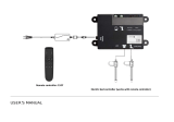
Vehicle 12-80 VDC Power Connection Cable
Caution:
For proper and safe installation, the input power cable must be connected to a fused circuit on the vehicle. This
fused circuit requires a ten Amp maximum time delay (slow blow) high interrupting rating fuse. If the supply
connection is made directly to the battery, the fuse should be installed in the positive lead within 5 inches of the
battery positive (+) terminal. Note: For North America, a UL Listed fuse is to be used.
Caution:
For installation by trained service personnel only.
Warning:
Risk of ignition or explosion. Explosive gas mixture may be vented from battery. Work only in well ventilated
area. Avoid creating arcs and sparks at battery terminals.
Note: Please see Power Adapter Cable for information on adapting an LXE VX1, VX2 or VX4 DC power supply to the
VX7.
1. To Vehicle Battery
2. To Vehicle Mounted Device or UPS Battery Pack
3. White (DC+)
4. Black (DC-)
5. Green (GND)
6. 12 – 80 VDC
E-EQ-VX7OGWW-P [ 13 ] VX7 User Guide

Vehicle 12-80 VDC Power Connection Cable
1. Vehicle Electrical System
2. 10 Amp Slow Blow Fuse
3. DC +
4. DC -
5. Vehicle Chassis
6. White
7. Black
8. Green
Note: Correct electrical polarity is required for safe and proper installation. Connecting the cable to the VX7 with the
polarity reversed will cause the VX7 fuse to be blown. See the following figure titled “Vehicle Connection Wiring Color
Codes” for additional wire color-coding specifics.
E-EQ-VX7OGWW-P [ 14 ] VX7 User Guide

How To: Connect Vehicle 12-80VDC Connection
How To: Connect Vehicle 12-80VDC Connection
1. The VX7 must be turned off and the power cable must be UNPLUGGED from the VX7.
2. While observing the fuse requirements specified above, connect the power cable as close as possible to the actual bat-
tery terminals of the vehicle. When available, always connect to un-switched terminals in vehicle fuse panel, after pro-
viding proper fusing.
ATTENTION:For uninterrupted power, electrical supply connections should not be made at any point after the ignition
switch of the vehicle.
3. Route the power cable the shortest way possible. The cable is rated for a maximum temperature of 105°C (221°F).
When routing this cable it should be protected from physical damage and from surfaces that might exceed this tem-
perature.
Do not expose the cable to chemicals or oil that may cause the wiring insulation to deteriorate.
If the vehicle is equipped with a panel containing Silicon Controller Rectifiers (SCR’s), avoid routing the power cable in
close proximity to these devices.
Always route the cable so that it does not interfere with safe operation and maintenance of the vehicle.
Use proper electrical and mechanical fastening means for terminating the cable. Properly sized “crimp” type electrical
terminals are an accepted method of termination. Please select electrical connectors sized for use with 18AWG (1mm
2
)
conductors.
Wiring color codes for LXE supplied DC input power cabling:
Vehicle Supply Wire Color
+12 - 80VDC (DC +) White
Return (DC -) Black
Vehicle Chassis GND Green
4. Provide mechanical support for the cable by securing it to the vehicle structure at approximately one foot intervals, tak-
ing care not to over tighten and pinch conductors or penetrate outer cable jacket.
5. Refer to the following sections to complete the power connection to the VX7.
E-EQ-VX7OGWW-P [ 15 ] VX7 User Guide

How To: Connect VX7 without a UPS Battery Pack
How To: Connect VX7 without a UPS Battery Pack
A. Vehicle Battery
B. Vehicle Power Connection Cable
C. VX7 Computer
1. Connect the power cable to the vehicle’s electrical system as described in “Connect Vehicle 12-80VDC Connection”.
2. Connect the power cable to the VX7 by aligning the water-tight connector pins to the power connector on the bottom of
the VX7; push down on the water-tight connector and twist it to fasten securely.
3. Turn the VX7 on.
E-EQ-VX7OGWW-P [ 16 ] VX7 User Guide
/