Page is loading ...

DeZURIK, Inc. Sartell, Minnesota USA | Phone: 320-259-2000 | DeZURIK.com | [email protected]
APCO AVV-1800/1800K DUAL
BODY COMBINATION AIR
VALVES
Instruction D12024
March 2023

DeZURIK
Instruction and Operating Manual Page 2 © 2023 DeZURIK, Inc.
Instructions
These instructions are for use by personnel who are responsible for the installation, operation and
maintenance of DeZURIK valves, actuators or accessories.
Safety Messages
All safety messages in the instructions are identified by a general warning sign and the signal word CAUTION,
WARNING or DANGER. These messages indicate procedures to avoid injury or death.
Safety label(s) on the product indicate hazards that can cause injury or death. If a safety label becomes difficult
to see or read, or if a label has been removed, please contact DeZURIK for replacement label(s).
Personnel involved in the installation or maintenance of valves should be constantly alert to potential
emission of pipeline material and take appropriate safety precautions. Always wear suitable protection
when dealing with hazardous pipeline materials. Handle valves which have been removed from service
with suitable protection for any potential pipeline material in the valve.
Inspection
Your DeZURIK product has been packaged to provide protection during shipment; however, items can be
damaged in transport. Carefully inspect the unit for damage upon arrival and file a claim with the carrier if
damage is apparent.
Parts
Replaceable wear parts are listed on the assembly drawing. These parts can be stocked to minimize
downtime. Order parts from your local DeZURIK sales representative or directly from DeZURIK. When ordering
parts please provide the following information:
If the valve has a data plate: please include the 7-digit part number with either 4-digit revision number
(example: 9999999R000) or 8-digit serial number (example: S1900001) whichever is applicable. The
data plate will be attached to the valve assembly. Also, include the part name, the assembly drawing
number, the balloon number and the quantity stated on the assembly drawing.
If there isn't any data plate visible on the valve: please include valve model number, part name, and
item number from the assembly drawing. You may contact your local DeZURIK Representative to help
you identify your valve.
DeZURIK Service
DeZURIK service personnel are available to maintain and repair all DeZURIK products. DeZURIK also offers
customized training programs and consultation services. For more information, contact your local DeZURIK
sales representative or visit our website at DeZURIK.com.

DeZURIK
APCO AVV-1800/1800K Dual Body Combination Air Valves
March 2023 Page 3 D12024
Table of Contents
Description ........................................................................................................................................................ 4
Handling and Storage ........................................................................................................................................ 4
Installation ......................................................................................................................................................... 4
Fusion Bonded Epoxy Coated Valves ................................................................................................................ 5
AVV-1800K Assembly ....................................................................................................................................... 5
Maintenance ...................................................................................................................................................... 7
Disassembly Procedure ................................................................................................................................. 7
AVV- 140 and 140H Valve 1-3” (25-80mm) ................................................................................................ 7
AVV-140 with AVRT Option Disassembly Procedure ................................................................................. 8
AVV-150 Air/Vacuum Valve 4-18” (100-450mm) Disassembly ................................................................... 9
ARV-50A/200A/200 Air Release Valve Disassembly .................................................................................. 9
Assembly Procedure .................................................................................................................................... 10
ARV-50A/200A/200 Air Release Valve Assembly .................................................................................... 10
AVV-150 Air/Vacuum Valves 4-18” (100-450mm) Assembly .................................................................... 10
AVV-140/140H Air/Vacuum Valves 1-3” (25-75mm) Assembly ................................................................ 10
AVV-140 with AVRT Option Assembly Procedure .................................................................................... 11
Testing ..................................................................................................................................................... 11
Operation ........................................................................................................................................................ 11
Drawings ......................................................................................................................................................... 12
Figure 1: Connecting Parts for Dual Body AVV ........................................................................................ 12
Figure 2A: AVV-140 0.5-3” (15-80mm) Air/Vacuum Valve ........................................................................ 13
Figure 2B: AVV-140 AVRT Option ........................................................................................................... 14
Figure 3: AVV-140H 1-3” (25-80mm) Air/Vacuum Valve for High Pressure Service ................................. 15
Figure 4: AVV-150 4-18” (100-450mm) Air/Vacuum Valve ....................................................................... 16
Figure 5: ARV-50A Air Release Valve ...................................................................................................... 17
Figure 6: ARV-200A Air Release Valve .................................................................................................... 18
Figure 7: ARV-200 Air Release Valve ...................................................................................................... 19
Troubleshooting ............................................................................................................................................... 20

DeZURIK
APCO AVV-1800/1800K Dual Body Combination Air Valves
March 2023 Page 4 D12024
Description
The AVV-1800/1800K are Dual Body Combination Valves with an Air/Vacuum Valve piped to an Air Release
Valve. The AVV-1800 and AVV-1800K are functionally the same. The AVV-1800 ships fully assembled from
the factory. The AVV-1800K ships with the Air/Vacuum Valve, Air Release Valve, and piping kit. The customer
will pipe the Air Release Valve to the Air/Vacuum Valve.
The APCO AVV-1800 Dual Body Combination Air Valve should always be installed in a vertical position. An
isolation valve between this unit and the transmission (pipeline) system is recommended. Where to use:
• High points in pipelines where the hydraulic gradient and flow conditions are such that a negative
pressure can possibly occur.
• High points on sections of pipeline having water velocities in excess of 10 F.P.S.
• Adjacent to any quick closing valve in a pipeline such as a check or gate valve where vacuum can
occur upon closure.
• On the discharge of larger deep well turbine pumps between the pump and the check valve.
• If an Air/Vacuum Valve is to be installed inside a pump house, use threaded or flanged connections and
pipe back into the well or to outside. This will greatly muffle the high noise level caused by the air being
discharged and provide for drainage of any small amount of water or water vapor that may accumulate.
Handling and Storage
Lifting the valve improperly may damage it. Do not fasten lifting devices to piping, or
attached components. Lift the valve with slings, chains, or cables fastened around the
valve body, or fastened to bolts or rods through bolt holes in the flanges.
If installation will be delayed, refer to Form 1454 – Recommended Long & Short-Term Storage Procedures
Installation
• Before installation, remove foreign material such as weld spatter, oil, grease, and dirt from the pipeline.
• Prepare pipe ends and install valves in accordance with the pipe manufacturer’s instructions for the
joint used.
• Tighten the flange bolts or studs in a crisscross pattern and minimum of four stages.

DeZURIK
APCO AVV-1800/1800K Dual Body Combination Air Valves
March 2023 Page 5 D12024
Fusion Bonded Epoxy Coated Valves
Valves with fusion bonded epoxy coated exterior paint require flat washers to be
installed under the flange nuts when installing the valve to the pipeline flange to prevent
the coating from cracking or chipping.
AVV-1800K Assembly
Assembling the Combination Valve incorrectly or while not wearing appropriate
Personal Protective Equipment (PPE) can cause personal injury. In addition, when
lifting, use appropriate lifting hooks/straps to avoid personal injury.
Do not deflect the piping joints. While applying torque to tighten components,
minimize bending stresses in the piping kit components.
For the AVV-1800K, assemble the valves together as stated below:
1. Place the fully assembled AVV (Air/Vacuum Valve) on a flat surface.
2. Locate piping kit shipped with the valves.
3. For 1-3” (25-80mm) AVV-140/140H Only:
See Figures 1, 2, and 3 for part identification.
a. Remove ONLY the pipe plug (A25) in the side of body (A01) if applicable.
i. DO NOT remove pipe plug (A25) in the cover (A02).
b. Apply thread sealant to the threads in the port on the side of the Air/Vacuum Valve body (A01).
c. Apply Teflon tape to the threads on the nipple (P6).
d. Thread the nipple (P6) into the side port of the body (A01).
e. Apply thread sealant to the threads in the elbow (P7).
f. Thread the elbow (P7) onto the nipple (P6).
g. Using a wrench, tighten the elbow (P7) until secure and until the elbow is orientated vertically
with the exposed threads toward the top.
h. Apply Teflon tape to the threads on the outside of the elbow (P7).
i. Apply thread sealant to the threaded inlet of the Air Release Valve.
j. Thread the inlet of the fully assembled Air Release Valve onto the elbow (P7).
k. Using a chain wrench, tighten the Air Release Valve until secure.

DeZURIK
APCO AVV-1800/1800K Dual Body Combination Air Valves
March 2023 Page 6 D12024
AVV-1800K Assembly (Continued)
4. For 4-18” (100-450mm) AVV Only:
See Figures 1, 4, 5, 6, and 7 for part identification.
For information regarding larger Air/Vacuum Valves, contact your local DeZURIK sales representative.
a. Remove ONLY the upper pipe plug (A44) in the side of the body (A01) if applicable.
i. DO NOT remove the lower pipe plug (A44) in the side of the body (A01).
b. Apply thread sealant to the threads in the upper port on the side of the body (A01).
c. Apply Teflon tape to the threads on the nipple (P5).
d. Thread the nipple (P5) into the side port of the body (A01).
e. Apply thread sealant to the threads in the ball valve (P8).
f. Thread the ball valve (P8) onto the nipple (P5).
g. Using a wrench, tighten the ball valve (P8) until secure and until the handle is positioned toward
the side or bottom (NOTE: The handle will be in the way if it is on top.)
h. Apply Teflon tape to the threads on the nipple (P6).
i. Thread the nipple (P6) into the ball valve (P8).
j. Apply thread sealant to the threads in the elbow (P7).
k. Thread the elbow (P7) onto the nipple (P6).
l. Using a wrench, tighten the elbow (P7) until secure and until the elbow is orientated vertical with
the exposed threads toward the top.
m. Apply Teflon tape to the threads on the outside of the elbow (P7).
n. Apply thread sealant to the threaded inlet of the ARV Air Release Valve.
o. For the ARV-200 Air Release Valve Only (refer to Figure 7):
i. Apply Teflon tape to the threads on the outside of the reducer bushing (P9).
ii. Thread the reducer bushing (P9) into the inlet of the ARV-200.
iii. Using a wrench, tighten the reducer bushing (P9) until secure.
iv. Apply thread sealant to the threads on the inside of the reducer bushing (P9).
p. Thread the inlet of the fully assembled ARV Air Release Valve onto the elbow (P7).
q. Using a chain wrench, tighten the ARV Air Release Valve until secure.
5. Test the unit according to number 9 of the assembly procedure in the Maintenance section.

DeZURIK
APCO AVV-1800/1800K Dual Body Combination Air Valves
March 2023 Page 7 D12024
Maintenance
Combination Air Valves are automatic in operation and require very little or no maintenance.
It is recommended that they be checked visually semi-annually for leakage. A malfunction of the valve will be
evident by leakage of the media out of the orifice of plug stem or by the seating area of the exhaust port.
Should a malfunction occur, the following steps should be taken to repair the valve.
Disassembly Procedure
AVV- 140 and 140H Valve 1-3” (25-80mm)
See Figure 1 and Figure 2 for part identification.
Servicing the Air Valve while the pipeline is under pressure can cause personal injury or
equipment damage. Relieve pipeline pressure or shut off isolation valve before servicing the
Air Valve.
1. Relieve pipeline pressure or shut off isolation valve on inlet pipe.
Do not completely remove pipe plug or cover screws while the valve is under pressure.
2. Loosen pipe plug in cover (A02) to relieve internal pressure. Do not completely remove pipe plug
(A02) while the valve is under pressure.
3. Inspect exhaust port on top. If any foreign matter or dirt is preventing float (A14) from seating
properly against the seat (A06), clean or replace as necessary.
4. Perform a seat test: Replace pipe plug and slowly fill valve chamber by cracking open isolation
valve on inlet pipe. If seepage persists, repeat steps 1 and 2 and proceed as follows:
5. Remove cover screws (A04) and cover (A02) with all the internal components together from the
valve body (A01).

DeZURIK
APCO AVV-1800/1800K Dual Body Combination Air Valves
March 2023 Page 8 D12024
Maintenance (Continued)
AVV-140 with AVRT Option Disassembly Procedure
See Figures 1A & 1B for part identification.
Servicing the Air/Vacuum Valve while the pipeline is under pressure can cause
personal injury or equipment damage. Relieve pipeline pressure or shut off isolation
valve before servicing the Air/Vacuum Valve.
1. Relieve pipeline pressure or shut off isolation valve on inlet pipe.
Do not completely remove pipe plug or cover screws while the valve is under pressure
2. Loosen pipe plug (A25) in cover (A02) to relieve internal pressure. Do not completely remove pipe
plug (A25) while the valve is under pressure.
3. Inspect exhaust port and mushroom cap assembly (A28, A29, & A30). If any foreign matter or dirt
is preventing float (A14) from seating properly against the seat (A06), clean or replace as
necessary.
4. Perform a seat test: Replace pipe plug (A25) and slowly fill valve chamber by cracking open
isolation valve on inlet pipe. If seepage persists, repeat steps 1 and 2 and proceed as follows:
5. Remove cover screws (A04) and cover (A02) with all the internal components together from the
valve body (A01).
6. Remove baffle screws (A34) and baffle (A24) and lift out seat (A06) from the recess in the cover
(A02).
7. Remove float (A14), spring (A42), float guide (A33) and baffle plug (A41) from baffle (A24).
8. Clean all surfaces before re-assembly. Replace all defective parts.

DeZURIK
APCO AVV-1800/1800K Dual Body Combination Air Valves
March 2023 Page 9 D12024
Maintenance (Continued)
AVV-150 Air/Vacuum Valve 4-18” (100-450mm) Disassembly
See Figure 4 for part identification.
Servicing the Air/Vacuum Valve while the pipeline is under pressure can cause personal
injury or equipment damage. Relieve pipeline pressure or shut off isolation valve before
servicing the Air/Vacuum Valve.
1. Relieve pipeline pressure or shut off isolation valve at inlet to Air/Vacuum Valve before servicing the
Air Valve.
Do not completely remove pipe plugs or cover bolts while the valve is under pressure.
2. Slowly remove pipe plug near inlet of valve body (A01) to relieve internal pressure and to drain the
unit.
3. Check to see if foreign matter or dirt is preventing float (A14) from seating properly against seat
(A06). Clean as necessary.
4. Perform a seat test. Replace pipe plug and slowly fill valve chamber by cracking open isolation
valve on inlet pipe. If seepage persists, repeat Steps 1 and 2 and proceed as follows:
5. Remove cover bolts (A04) and cover (A02).
6. Remove seat screws (A16/A34) and remove seat (A06) from cover (A02).
7. Inspect seat (A06) and float (A14) seating surfaces for damage. Replace if necessary.
8. Inspect all other parts of the valve such as guide bushings (A26 & A43), bumper (A40), and float
guide (A33) if applicable. Replace if necessary.
ARV-50A/200A/200 Air Release Valve Disassembly
See Figures 5, 6, and 7 for part identification.
1. Remove cover bolts (R04) and cover (R02) from the valve body (R01).
Note: All internals are attached to the cover.
2. If cover gasket (R03) is torn or damaged, clean flange surfaces of cover (R02) and body (R01),
replace cover gasket (R03).
3. Clean and inspect all components attached to the cover (R02).
4. Inspect float (R10/R14) for the presence of water inside float. Replace float if damaged.

DeZURIK
APCO AVV-1800/1800K Dual Body Combination Air Valves
March 2023 Page 10 D12024
Maintenance (Continued)
Assembly Procedure
ARV-50A/200A/200 Air Release Valve Assembly
See Figures 5, 6, and 7 for part identification.
1. Assemble cover (R02) and attached components to body (R01), installing new gasket (R03) if
necessary. Tighten bolts (R04) opposite each other in rotation.
AVV-150 Air/Vacuum Valves 4-18” (100-450mm) Assembly
See Figures 4 for part identification.
1. Clean surface of recess in cover (A02) and install seat (A06) with seat screws (A16).
2. Install bumper (A40) and float (A14) in place.
3. Assemble cover (A02) and gasket (A03) to body (A01). Tighten cover screws (A04) alternating in a
crisscross pattern.
4. Install and secure pipe plug (A44) and move onto Testing section to perform a seat test.
AVV-140/140H Air/Vacuum Valves 1-3” (25-75mm) Assembly
See Figures 2 and 3 for part identification.
1. Install float (A14) and baffle plug (A41) if included with float guide (A33) to baffle (A24).
For 3” valve size: Secure float (A14) together with float guide (A33) to the baffle (A24) with float
bushing (A26).
2. Install seat (A06) to cover (A02).
3. With cover (A02) lying upside down on a level work bench, set the baffle assembly created in steps
1 & 2 in cover (A02). Align and match screw holes through the baffle (A24), seat (A06), and cover
(A02), by inserting and turning baffle screw (A34) with fingers.
4. Before tightening baffle screws (A34) with an open (box) wrench, position baffle (A24) by allowing
float (A14) to center perfectly in the seat (A06), then tighten baffle screws (A34) alternating in a
crisscross pattern.
5. If water diffuser is required, remove baffle plug (A41) with the float guide (A33) and slip the water
diffuser around the baffle (A24). Then secure float (A14) and water diffuser to baffle (A24) with
baffle plug (A41) and float guide (A33).
For 3” valve size: Remove float guide (A33) and slip water diffuser around the baffle (A24). Then
secure float (A14) and water diffuser in place with the float guide (A33).
6. Install new cover gasket (A03) and set cover (A02) assembly to the body (A01), then tighten cover
screws (A04) alternating in a crisscross pattern.
7. Install and secure pipe plug (A25) and move onto Testing section to perform a seat test.

DeZURIK
APCO AVV-1800/1800K Dual Body Combination Air Valves
March 2023 Page 11 D12024
Maintenance (Continued)
AVV-140 with AVRT Option Assembly Procedure
1. Install baffle plug (A41), float guide (A33), spring (A42), and float (A14) to baffle (A24). Replace any
damaged parts.
For 3” valve size: Secure float (A14), spring (A42), and float guide (A33) to the baffle (A24) with
float bushing (A26).
2. Install seat (A06) to cover (A02).
3. With cover (A02) lying upside down on a level work bench, set the baffle assembly on cover (A02).
Align and match screw holes through the baffle (A24), seat (A06), and cover (A02), by inserting
and turning baffle screw (A34) with fingers.
4. Before tightening baffle screws (A34) with an open (box) wrench, position baffle (A24) by allowing
float (A14) to center perfectly in the seat (A06), then tighten baffle screws alternating in a crisscross
pattern.
5. If water diffuser is required, remove baffle plug (A41) with the float guide (A33) and slip the water
diffuser around the baffle (A24). Then secure float (A14), spring (A42), and float guide (A33) to the
baffle (A24) with float bushing (A26).
For 3” valve size: Remove float guide (A33) and slip water diffuser around the baffle (A24). Then
secure float (A14) and water diffuser in place with the float guide.
6. Install new cover gasket (A03) and set cover (A02) assembly to the body (A01), then tighten cover
screws (A04) alternating in a crisscross pattern.
7. Install and secure pipe plug (A25) and move onto Testing section to perform a seat test.
Testing
See Figures 2-6 for part identification.
1. Perform a seat test. Restore pipeline pressure and slowly fill the Air/Vacuum valve chamber by
cracking open the isolation valve below Air/Vacuum Valve. If seepage occurs once the float (A14)
or needle (R07) is in contact with the seat (A06/R06), reference to the “Disassembly Procedure”
and replace seat, needle, and/or float.
2. If there is no seepage during the seat test, fully open isolation valve.
Operation
Combination Air Valves prevent accumulation of air at high points within a system by exhausting large volumes
of air as the system is filled and releasing accumulated pockets of air while the system is operational and
under pressure. They also prevent potentially destructive vacuums from forming by admitting large quantities
of air into the system. This can occur during power outage, water column separation or sudden rupture of the
pipeline. Additionally, these valves allow the system to be easily drained because air will re-enter as needed.

DeZURIK
APCO AVV-1800/1800K Dual Body Combination Air Valves
March 2023 Page 12 D12024
Drawings
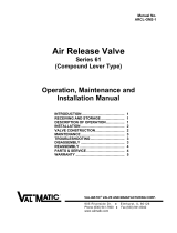
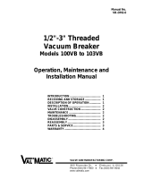
FOR 1-3” AVV DUAL BODY ONLY
FOR 4-18” AVV DUAL BODY ONLY
Item No.
Description
P5
Nipple
P6
Nipple
P7
Elbow
P8
Ball Valve or Gate Valve (See Note 1)
P9
Reducer Bushing (See Note 2)
Notes:
1. A ball valve is used for clean water and a
gate valve is used for sewage valves.
2. The reducer bushing is only used when
the ARV 200 is used.
Figure 1: Connecting Parts for Dual Body AVV

DeZURIK
APCO AVV-1800/1800K Dual Body Combination Air Valves
March 2023 Page 13 D12024
Drawings (Continued)
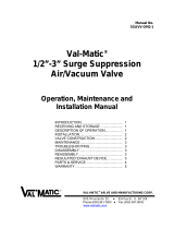
Part No.
Description
Part No.
Description
A01
Body
A26
Float Bushing
A02
Cover
A33
Float Guide
A03
Cover Gasket
A34
Baffle Screws
A04
Cover Bolts
A41
Baffle Plug
A05
Washer
A44
Water Diffuser (WD Option)
A06
Seat
A50
Inlet Nipple (F1N/F2N Only)
A14
Float
A51
Inlet Flange (F1N/F2N Only)
A24
Baffle
A54
Outlet Nipple (FL Only)
A25
Pipe Plug
A55
Outlet Flange (FL Only)
Figure 2A: AVV-140 0.5-3” (15-80mm) Air/Vacuum Valve

DeZURIK
APCO AVV-1800/1800K Dual Body Combination Air Valves
March 2023 Page 14 D12024
Drawings (Continued)
Part No.
Description
A28
Mushroom Cap
A29
Pipe Nipple
A30
Reducer Bushing (0.5” AVRT Option Only)
A42
Spring
Figure 2B: AVV-140 AVRT Option

DeZURIK
APCO AVV-1800/1800K Dual Body Combination Air Valves
March 2023 Page 15 D12024
Drawings (Continued)
Part No.
Description
Part No.
Description
A01
Body
A34
Baffle Screw
A02
Cover
A42
Seat Plug
A03
Cover Gasket / O-Ring
A45
O-Ring Seal
A04
Cover Bolt
A47
Compression Spring (2” & 3” Only)
A06
Seat
A50
Nipple
A14
Float Assembly
A51
Inlet Flange
A24
Baffle
A54
Nipple
A25
Pipe Plug
A55
Outlet Flange
A26
Bushing Guide
A59
Washer
A33
Float Guide
Figure 3: AVV-140H 1-3” (25-80mm) Air/Vacuum Valve for High Pressure Service

DeZURIK
APCO AVV-1800/1800K Dual Body Combination Air Valves
March 2023 Page 16 D12024
Drawings (Continued)
Part No.
Description
Part No.
Description
A01
Body
A28
Hood
A02
Cover
A29
Hood Screws
A03
Cover Gasket / O-Ring
A40
Bumper
A04
Cover Bolts
A42
Lower Retaining Ring (18” Only)
A06
Seat
A43
Upper Float Guide Bushing
A14
Float
A44
1” Pipe Plug
A16
Seat Screws
A58
Bug/Rock Screen (Optional)
A26
Lower Float Guide Bushing
A59
Cover Bolt Washer (Note 3)
A27
Upper Retaining Ring (18” Only)
A60
Hood Washers (Note 3)
Figure 4: AVV-150 4-18” (100-450mm) Air/Vacuum Valve

DeZURIK
APCO AVV-1800/1800K Dual Body Combination Air Valves
March 2023 Page 17 D12024
Drawings (Continued)
Item No.
Description
R01
Body
R02
Cover
R03
Cover Gasket
R04
Cover Bolts
R05
Lever Frame
R06
Seat
R07
Needle
R08
Lever Pin
R09
Float Lever
R10
Float
R11
Pin Retainer
R12
Washer (Epoxy/FBE Coating Only
R16
1” NPT to 3/4” NPT Reducer
R17
1” NPT to 1/2” NPT Reducer
Figure 5: ARV-50A Air Release Valve

DeZURIK
APCO AVV-1800/1800K Dual Body Combination Air Valves
March 2023 Page 18 D12024
Drawings (Continued)
Item No.
Description
R01
Body
R02
Cover
R03
Cover Gasket
R04
Cover Bolts
R05
Leverage Frame
R06
Seat (5/16 Orifice Only)
R07
Needle
R09
Needle Lever
R10
Lever Pin
R11
Pin Retainer
R12
Connecting Link
R13
Float Lever
R14
Float
R15
1/2” NPT Pipe Plug
R16
Washer
R28
Nipple (F1N Only)
R29
Flange (F1N Only)
Figure 6: ARV-200A Air Release Valve

DeZURIK
APCO AVV-1800/1800K Dual Body Combination Air Valves
March 2023 Page 19 D12024
Drawings (Continued)
Item No.
Description
R01
Body
R02
Cover
R03
Cover Gasket
R04
Cover Bolts
R05
Leverage Frame
R06
Seat
R07
Needle
R09
Needle Lever
R10
Lever Pin
R11
Retaining Ring/Cotter Pin
R12
Connecting Link
R13
Float Lever
R14
Float
R15
Leverage Frame Gasket
R16
Leverage Frame Screw
R17
Leverage Frame Washer
R18
1/2” NPT Drain Pipe Plug
R19
1” NPT Pipe Plug
R20
SAE Flat Washer
R28
Nipple (F1N and F2N Only)
R29
Flange (F1N and F2N Only)
Figure 7: ARV-200 Air Release Valve

DeZURIK
APCO AVV-1800/1800K Dual Body Combination Air Valves
March 2023 Page 20 D12024
Troubleshooting
Condition
Possible Cause
Corrective Action
Valve leaks at flange joint.
Loose flange bolting.
Tighten flange bolting.
Blown flange gasket.
Replace flange gasket.
Misalignment or damage to field
piping and supports.
Adjust misalignment or repair
piping or supports.
Damaged flange face/s or
improper flange connections.
Repair flange, replace valve
body or adjust flange
connections.
Valve leaks out of outlet port.
Line pressure is under 10 psi
(70kPa).
Contact factory for low pressure
application information.
Worn needle and/or orifice.
Replace needle and/or orifice.
Float does not move freely.
Readjust position of leverage
frame to cover.
Float has liquid in it.
Replace float.
Dirty seat and/or float.
Clean seat and/or float.
Worn seat and/or float.
Replace seat and/or float.
Dirty needle and/or orifice of
leverage frame.
Clean needle and/or orifice of
leverage frame.
Float linkage is dirty.
Clean float linkage.
/