Page is loading ...

DeZURIK, Inc. Sartell, Minnesota USA | Phone: 320-259-2000 | www.dezurik.com | [email protected]
APCO AVV-140/150
AIR/VACUUM VALVE WITH
OPTIONAL CSV SURGE
CHECK VALVE
Instruction D12021
March 2023

DeZURIK
Instruction and Operating Manual Page 2 © 2023 DeZURIK, Inc.
Instructions
These instructions are for use by personnel who are responsible for the installation, operation and
maintenance of DeZURIK valves, actuators or accessories.
Safety Messages
All safety messages in the instructions are identified by a general warning sign and the signal word CAUTION,
WARNING or DANGER. These messages indicate procedures to avoid injury or death.
Safety label(s) on the product indicate hazards that can cause injury or death. If a safety label becomes difficult
to see or read, or if a label has been removed, please contact DeZURIK for replacement label(s).
Personnel involved in the installation or maintenance of valves should be constantly alert to potential
emission of pipeline material and take appropriate safety precautions. Always wear suitable protection
when dealing with hazardous pipeline materials. Handle valves which have been removed from service
with suitable protection for any potential pipeline material in the valve.
Inspection
Your DeZURIK product has been packaged to provide protection during shipment; however, items can be
damaged in transport. Carefully inspect the unit for damage upon arrival and file a claim with the carrier if
damage is apparent.
Parts
Replaceable wear parts are listed on the assembly drawing. These parts can be stocked to minimize
downtime. Order parts from your local DeZURIK sales representative or directly from DeZURIK. When ordering
parts please provide the following information:
If the valve has a data plate: please include the 7-digit part number with either 4-digit revision number
(example: 9999999R000) or 8-digit serial number (example: S1900001) whichever is applicable. The
data plate will be attached to the valve assembly. Also, include the part name, the assembly drawing
number, the balloon number and the quantity stated on the assembly drawing.
If there isn't any data plate visible on the valve: please include valve model number, part name, and
item number from the assembly drawing. You may contact your local DeZURIK Representative to help
you identify your valve.
DeZURIK Service
DeZURIK service personnel are available to maintain and repair all DeZURIK products. DeZURIK also offers
customized training programs and consultation services. For more information, contact your local DeZURIK
sales representative or visit our website at DeZURIK.com.

DeZURIK
APCO AVV 140/150 Air/Vacuum Valve with Optional CSV Surge Check Valve
March 2023 Page 3 D12021
Table of Contents
Description ........................................................................................................................................................ 4
Handling and Storage ........................................................................................................................................ 4
Installation ......................................................................................................................................................... 4
Fusion Bonded Epoxy Coated Valves ................................................................................................................ 4
Maintenance ...................................................................................................................................................... 5
Disassembly Procedure (AVV-140) ............................................................................................................... 5
Disassembly Procedure (AVV-150) ............................................................................................................... 6
Disassembly Procedure (CSV-1600A) ........................................................................................................... 7
Assembly Procedure (CSV-1600A) ................................................................................................................ 8
Assembly Procedure (AVV-140) .................................................................................................................... 9
Assembly Procedure (AVV-150) .................................................................................................................. 10
Operation ........................................................................................................................................................ 11
Drawings ......................................................................................................................................................... 12
Troubleshooting ............................................................................................................................................... 16

DeZURIK
APCO AVV 140/150 Air/Vacuum Valve with Optional CSV Surge Check Valve
March 2023 Page 4 D12021
Description
The APCO AVV Air/Vacuum Valve mounted on top of a CSV Surge Check Valve is designed to eliminate
critical shock conditions occurring in those installations where the operating conditions cause a regular air
valve to slam closed. This slow closing feature protects the Air/Vacuum valve and also prevents the
Air/Vacuum valve from creating a surge in the pipeline by slamming shut.
This type of Air/Vacuum Valve with Surge Check Valve should not be considered as relief for shock conditions
which develop elsewhere in the system. However, actual field tests prove the Surge Check Valve may protect
the Air/Vacuum Valve from damage by severe shut-off shock.
The Air/Vacuum Valve with Surge Check Valve should always be installed in a vertical position. An isolation
valve between this unit and the transmission (pipeline) system is recommended. Where to use:
• High points in pipelines where the hydraulic gradient and flow conditions are such that a negative
pressure can possibly occur.
• High points on sections of pipeline having water velocities in excess of 10 ft/s (3.1 m/s).
• Adjacent to any quick closing valve in a pipeline such as a check or gate valve where vacuum can
occur upon closure.
• On the discharge of larger deep well turbine pumps between the pump and the check valve.
• If an Air/Vacuum Valve is to be installed inside a pump house, use threaded or flanged connections and
pipe back into the well or to outside. This will greatly muffle the high noise level caused by the air being
discharged and provide for drainage of any small amount of water or water vapor that may accumulate.
Handling and Storage
Lifting the valve improperly may damage it. Do not fasten lifting devices to piping, or
attached components. Lift the valve with slings, chains, or cables fastened around the
valve body, or fastened to bolts or rods through bolt holes in the flanges.
If installation will be delayed, refer to Form 1454 – Recommended Long & Short-Term Storage Procedures
Installation
• Before installation, remove foreign material such as weld spatter, oil, grease, and dirt from the pipeline.
• Prepare pipe ends and install valves in accordance with the pipe manufacture’s instructions for the joint
used.
• Tighten the flange bolts or studs in a crisscross pattern and minimum of four stages.
Fusion Bonded Epoxy Coated Valves
Valves with fusion bonded epoxy coated exterior paint require flat washers to be
installed under the flange nuts when installing the valve to the pipeline flange to prevent
the coating from cracking or chipping.

DeZURIK
APCO AVV 140/150 Air/Vacuum Valve with Optional CSV Surge Check Valve
March 2023 Page 5 D12021
Maintenance
The APCO AVV-140/150 Air/Vacuum Valve with Optional CSV Surge Check Valve is automatic in operation
and requires very little maintenance. It should always be installed in a vertical position.
A semi-annual visual inspection for leakage is recommended. A malfunction of the Air/Vacuum Valve can be
identified by the seepage of water through the exhaust port, while malfunction of the Surge Check Valve would
be a substantial amount of spillage through the Air/Vacuum exhaust port during pump start-up. Should a
malfunction occur, the following steps should be taken to repair the valve:
Disassembly Procedure (AVV-140)
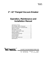
See Figure 1 for part identification.
Servicing the Air Valve while the pipeline is under pressure can cause personal injury or
equipment damage. Relieve pipeline pressure or shut off isolation valve before servicing the
Air Valve.
1. Relieve pipeline pressure or shut off isolation valve on inlet pipe.
Do not completely remove pipe plug or cover screws while the valve is under pressure.
2. Loosen pipe plug in cover (A02) to relieve internal pressure. Do not completely remove pipe plug (A02)
while the valve is under pressure.
3. Inspect exhaust port on top. If any foreign matter or dirt is preventing float (A14) from seating properly
against the seat (A06), clean or replace as necessary.
4. Perform a seat test: Replace pipe plug or tighten cover screws (A04) diagonally on size ½” and slowly
fill valve chamber by cracking open isolation valve on inlet pipe. If seepage persists, repeat steps 1
and 2 and proceed as follows:
5. Remove cover screws (A04) and cover (A02) with all the internal components together from the valve
body (A01).
6. Remove seat retaining screws (A34) and baffle (A24) and lift out seat (A06) from the recess in the
cover (A02) or baffle. For valves with water diffuser, it is necessary to remove the water diffuser by
removing baffle plug (A41) or float bushing (A26) for size 3”.
7. Remove cover gasket (A03).
8. Clean all surfaces.
9. If water diffuser is used, replacement is recommended.
10. Inspect all components. Replace if necessary.

DeZURIK
APCO AVV 140/150 Air/Vacuum Valve with Optional CSV Surge Check Valve
March 2023 Page 6 D12021
Disassembly Procedure (AVV-150)
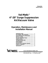
See Figure 2 for part identification.
Servicing the Air Valve while the pipeline is under pressure can cause personal injury or
equipment damage. Relieve pipeline pressure or shut off isolation valve before servicing
the Air Valve.
1. Relieve pipeline pressure or shut off isolation valve on inlet pipe.
Do not completely remove pipe plug while the valve is under pressure.
2. Slowly remove pipe plug near inlet of valve body (A01) to relieve internal pressure and to drain the unit.
3. Check to see if foreign matter or dirt is preventing float (A14) from seating properly against seat (A06).
Clean as necessary.
4. Perform a seat test: Replace pipe plug (A44) and slowly fill valve chamber by cracking open isolation
valve on inlet pipe. If seepage persists, repeat Steps 1 and 2 and proceed as follows:
5. Remove cover screws (A04) and cover (A02).
6. Remove seat screws (A16) and lift out seat (A06) from recess in cover (A02).
7. Inspect seat (A06) and float (A14) seating surfaces for damage. Replace if necessary.
8. Inspect all other parts of valve such as guide bushings (A26 & A43) and bumper (A40).

DeZURIK
APCO AVV 140/150 Air/Vacuum Valve with Optional CSV Surge Check Valve
March 2023 Page 7 D12021
Disassembly Procedure (CSV-1600A)
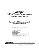
See Figures 1 & 2 for part identification.
Servicing the Surge Check Valve while the pipeline is under pressure can cause
personal injury or equipment damage. Relieve pipeline pressure or shut off isolation
valve before servicing the Surge Check Valve.
1. Relieve pipeline pressure or shut off isolation valve before servicing the Surge Check Valve.
2. Remove the Air/Vacuum Valve from the Surge Check Valve (See instructions in previous sections for
AVV-140 and AVV-150 disassembly).
3. Loosen seat retaining screws (S06).
4. Remove seat (S02). In some cases, it may be necessary to use penetrating oil or rust solvent to loosen
the rust that may have formed between the body (S01) and seat (S02). Also, it may be helpful to rotate
the seat in the body to break loose the seat retaining ball (S07). Check if the bore through the center of
the seat (S02) is worn.
5. Lift and remove plug (S03). Inspect plug assembly (S03) for any bent or worn features.
6. Remove bushing retaining ring (S11) and bushing (S05).
7. Clean all surfaces before re-assembly. Replace all defective parts.

DeZURIK
APCO AVV 140/150 Air/Vacuum Valve with Optional CSV Surge Check Valve
March 2023 Page 8 D12021
Assembly Procedure (CSV-1600A)
1. Install the parts inside the body (S01) in the following order:
a. Bushing (S05) and bushing retaining ring (S11) into the center bore of the body (S01).
b. Plug (S03) with the concave side facing upward.
c. Seat (S02) and seat retaining ball (S07). Tighten seat retaining screw (S06) when flush with flange
face.
Note: When assembled, make sure that both ends of plug stem are completely engaged in their
respective guides in both open and closed positions. Plug should freely move when
activated.
2. Attach the Air/Vacuum Valve to the Surge Check Valve (see instructions in following sections for
Assembly Procedures for the AVV-140 or AVV-150).
3. If valve was removed from pipeline, install valve in pipeline, and open isolation valve on inlet to Air
Valve. Valve is now back in service.

DeZURIK
APCO AVV 140/150 Air/Vacuum Valve with Optional CSV Surge Check Valve
March 2023 Page 9 D12021
Assembly Procedure (AVV-140)
1. Install float (A14) and baffle plug (A41), if included with float guide (A33), to baffle (A24).
For 3” valve size: Secure float (A14) together with float guide (A33) to the baffle (A24) with float
bushing (A26).
2. Install seat (A06) in body (A01).
3. With cover (A02) lying upside down on a level work bench, set the baffle assembly created in steps 1 &
2 in cover (A02). Align and match screw holes through the baffle (A24), seat (A06), and cover (A02),
by inserting and turning baffle screw (A34) with fingers.
4. Before tightening baffle screws (A34) with an open (box) wrench, position baffle (A24) by allowing float
(A14) to center perfectly in the seat (A06), then tighten baffle screws (A34) alternating in a crisscross
pattern.
5. If water diffuser is required, remove baffle plug (A41) with the float guide (A33) and slip the water
diffuser around the baffle (A24). Then secure float (A14) and water diffuser to baffle (A24) with baffle
plug (A41) and float guide (A33).
For 3” valve size: Remove float guide (A33) and slip water diffuser around the baffle (A24). Then
secure float (A14) and water diffuser in place with the float guide (A33).
6. Install new cover gasket (A03) and set cover (A02) assembly to the body (A01), then tighten cover
screws (A04) alternating in a crisscross pattern.
7. Install and secure pipe plug (A25) and perform a seat test per Step 4 of Disassembly Procedure.
8. If there is no more leakage, fully open isolation valve on the inlet pipe.

DeZURIK
APCO AVV 140/150 Air/Vacuum Valve with Optional CSV Surge Check Valve
March 2023 Page 10 D12021
Assembly Procedure (AVV-150)
1. Clean surface of recess in cover (A02) and install seat (A06) with seat screws (A16).
2. Install bumper (A40) and float (A14) in place.
3. Assemble cover (A02) and gasket (A03) to body (A01). Tighten cover screws (A04) alternating in a
crisscross pattern.
4. Install and secure pipe plug (A44) and perform a seat test per Step 4 of Disassembly Procedure.
5. If there is no more leakage, fully open isolation valve on the inlet pipe.

DeZURIK
APCO AVV 140/150 Air/Vacuum Valve with Optional CSV Surge Check Valve
March 2023 Page 11 D12021
Operation
The Air/Vacuum Valve is normally open and allows air to escape freely. Maximum discharge velocity is
approximately 300 feet per second (102 meters per second) at 6.7 psi (50kPa). However, good pipeline design
restricts velocity flows of air to 100 feet per second (34 meters per second) which occurs at approximately 1 psi
(7kPa).
The Surge Check Valve operates on the interphase between the kinetic energy in the relative velocity flows of
air and water. The Surge Check is a normally open valve, spring loaded, so that air passes through
unrestricted. When water rushes into the Surge Check Valve, the disc begins to close against the spring
tension and reduces the rate of flow of water into the air valve by means of throttling holes in the disc. This
ensures normal gentle closing of the Air/Vacuum Valve regardless of the initial velocity flows involved and
minimizes pressure surges when the valve closes.
As soon as the Air/Vacuum Valve is closed, the pressure on both sides of the Surge Check Valve disc
equalizes and the disc automatically returns to the open position. This means the Air/Vacuum Valve does not
need an incipient vacuum to open, but can open at any time the water level drops and line pressure
approaches atmospheric. This allows immediate full re-entry flow of air into the pipeline before a vacuum can
form.

DeZURIK
APCO AVV 140/150 Air/Vacuum Valve with Optional CSV Surge Check Valve
March 2023 Page 12 D12021
Drawings
Part No.
Description
Part No.
Description
A01
Body
A26
Float Bushing
A02
Cover
A33
Float Guide
A03
Cover Gasket
A34
Baffle Screws
A04
Cover Bolts
A41
Baffle Plug
A05
Washer
A44
Water Diffuser (WD Option)
A06
Seat
A50
Inlet Nipple (F1N/F2N Only)
A14
Float
A51
Inlet Flange (F1N/F2N Only)
A24
Baffle
A54
Outlet Nipple (FL Only)
A25
Pipe Plug
A55
Outlet Flange (FL Only)
Figure 1: AVV-140 Air/Vacuum Valve Sizes 0.5-3” (15-80mm)

DeZURIK
APCO AVV 140/150 Air/Vacuum Valve with Optional CSV Surge Check Valve
March 2023 Page 13 D12021
Drawings (Continued)
Part No.
Description
Part No.
Description
A01
Body
A28
Hood
A02
Cover
A29
Hood Screws
A03
Cover Gasket / O-Ring
A40
Bumper
A04
Cover Bolts
A42
Lower Retaining Ring (18” Only)
A06
Seat
A43
Upper Float Guide Bushing
A14
Float
A44
1” Pipe Plug
A16
Seat Screws
A58
Bug/Rock Screen (Optional)
A26
Lower Float Guide Bushing
A59
Cover Bolt Washer (Note 3)
A27
Upper Retaining Ring (18” Only)
A60
Hood Washers (Note 3)
Figure 2: AVV-150 Air/Vacuum Valve Sizes 4-18” (100-450mm)

DeZURIK
APCO AVV 140/150 Air/Vacuum Valve with Optional CSV Surge Check Valve
March 2023 Page 14 D12021
Drawings (Continued)
Item No.
Description
S01
BODY
S02
SEAT
S03
PLUG
S05
BUSHING
S06
SEAT RETAINING SCREW
S07
SEAT RETAINING BALL
S11
BUSHING RETAINING RING (NOTE 1)
Note 1: When corrosion resistant body materials are
used, a threaded retainer is used. Standard retainer is
a retaining ring as shown in the drawing.
Figure 3: CSV-1600A Surge Check Valve Sizes 3-18” (80-450mm)

DeZURIK
APCO AVV 140/150 Air/Vacuum Valve with Optional CSV Surge Check Valve
March 2023 Page 15 D12021
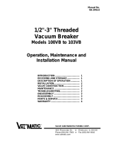
Drawings (Continued)
Connecting Parts
Item No.
Description
P1
Gasket
P2
Threaded Rod
P3
Nut
P4
Nipple
Figure 4: Connecting Parts

DeZURIK
APCO AVV 140/150 Air/Vacuum Valve with Optional CSV Surge Check Valve
March 2023 Page 16 D12021
Troubleshooting
Condition
Possible Cause
Corrective Action
Valve leaks at flange joint.
Loose flange bolting.
Tighten flange bolting.
Blown flange gasket.
Replace flange gasket.
Misalignment or damage to field
piping and supports.
Adjust misalignment or repair
piping or supports.
Damaged flange face/s or
improper flange connections.
Repair flange, replace valve
body or adjust flange
connections.
Valve leaks out of outlet port.
Dirty seat and/or float.
Clean seat and/or float.
Worn seat and/or float.
Replace seat and/or float.
Line pressure is under 10 psi
(70kPa).
Contact DeZURIK representative
for low pressure applications.
Float linkage is dirty.
Clean float linkage.

Limited Warranty
DeZURIK, Inc. (“Seller”) manufactured products, auxiliaries and parts thereof that we manufacture for a period of twenty-four (24) months from date
of shipment from Seller’s factory, are warranted to the original purchaser only against defective workmanship and material, but only if properly stored,
installed, operated, and serviced in accordance with Seller’s recommendations and instructions.
For items proven to be defective within the warranty period, your exclusive remedy under this limited warranty is repair or replacement of the defective
item, at Seller’s option, FCA Incoterms 2020 Seller’s facility with removal, transportation, and installation at your cost.
Products or parts manufactured by others but furnished by Seller are not covered by this limited warranty. Seller may provide repair or replacement
for other’s products or parts only to the extent provided in and honored by the original manufacturer’s warranty to Seller, in each case subject to the
limitations contained in the original manufacturer’s warranty.
No claim for transportation, labor, or special or consequential damages or any other loss, cost or damage is being provided in this limited warranty.
You shall be solely responsible for determining suitability for use and in no event shall Seller be liable in this respect.
This limited warranty does not warrant that any Seller product or part is resistant to corrosion, erosion, abrasion or other sources of failure, nor does
Seller warrant a minimum length of service.
Your failure to give written notice to us of any alleged defect under this warranty within twenty (20) days of its discovery, or attempts by someone other
than Seller or its authorized representatives to remedy the alleged defects therein, or failure to return product or parts for repair or replacement as
herein provided, or failure to store, install, or operate said products and parts according to the recommendations and instructions furnished by Seller
shall be a waiver by you of all rights under this limited warranty.
This limited warranty is voided by any misuse, modification, abuse or alteration of Seller’s product or part, accident, fire, flood or other Act of God, or
your failure to pay entire contract price when due.
The foregoing limited warranty shall be null and void if, after shipment from our factory, the item is modified in any way or a component of another
manufacturer, such as but not limited to; an actuator is attached to the item by anyone other than a Seller factory authorized service personnel.
All orders accepted shall be deemed accepted subject to this limited warranty, which shall be exclusive of any other or previous warranty, and this
shall be the only effective guarantee or warranty binding on Seller, despite anything to the contrary contained in the purchase order or represented by
any agent or employee of Seller in writing or otherwise, notwithstanding, including but not limited to implied warranties.
THE FOREGOING REPAIR AND REPLACEMENT LIMITED WARRANTY IS IN LIEU OF ALL OTHER WARRANTIES, OBLIGATIONS AND
LIABILITIES, INCLUDING, BUT NOT LIMITED TO, ALL WARRANTIES OF FITNESS FOR A PARTICULAR PURPOSE OR OF MERCHANTABILITY
OR OTHERWISE, EXPRESSED OR IMPLIED IN FACT OR BY LAW, AND STATE SELLER’S ENTIRE AND EXCLUSIVE LIABILITY AND YOUR
EXCLUSIVE REMEDY FOR ANY CLAIM IN CONNECTION WITH THE SALE AND FURNISHING OF SERVICES, GOODS OR PARTS, THEIR
DESIGN, SUITABILITY FOR USE, INSTALLATION OR OPERATIONS. NEITHER ANY PERFORMANCE OR OTHER CONDUCT, NOR ANY ORAL
OR WRITTEN INFORMATION, STATEMENT, OR ADVICE PREPARED BY SELLER OR ANY OF OUR EMPLOYEES OR AGENTS WILL CREATE A
WARRANTY, OR IN ANY WAY INCREASE THE SCOPE OR DURATION OF THE LIMITED WARRANTY.
Disclaimer
Metric fasteners should not be used with ASME Class 150/300 bolt holes and flange bolt patterns. If you use metric fasteners with ASME Class 150/300
bolt holes and flange bolt patterns, it may lead to product failure, injury, and loss of life. DeZURIK Inc. disclaims all liability associated with the use of
metric fasteners with ASME Class 150/300 bolt holes and flange patterns, including but not limited to personal injury, loss of life, loss of product,
production time, equipment, property damage, lost profits, consequential damages of any kind and environment damage and/or cleanup. Use of metric
fasteners with ASME Class 150/300 bolt holes and flange bolt patterns is a misuse that voids all warranties and contractual assurances. If you use
metric fasteners with ASME Class 150/300 bolt holes and flange bolt patterns, you do so at your sole risk and any liability associated with such use shall
not be the responsibility of DeZURIK, Inc. In addition to the foregoing, DeZURIK’s Manufacturer’s Conditions apply.
Limitation of Liability
IN NO EVENT SHALL SELLER BE LIABLE FOR ANY DIRECT, INDIRECT, SPECIAL, PUNITIVE, EXEMPLARY, OR CONSEQUENTIAL DAMAGES
(INCLUDING, BUT NOT LIMITED TO; DAMAGE TO OR LOSS OF OTHER PROPERTY OR EQUIPMENT, BUSINESS INTERUPTION, COST OF
SUBSTITUTE PRODUCTS, LOSS OF TIME, LOSS OF PROFITS OR REVENUE, COST OF CAPTIAL, LOSS OF USE, OR DIMINUTION IN VALUE)
WHATSOEVER, AND SELLER’S LIABILITY, UNDER NO CIRCUMSTANCES, WILL EXCEED THE CONTRACT PRICE FOR THE GOODS AND/OR
SERVICES FOR WHICH LIABILITY IS CLAIMED. ANY ACTION FOR BREACH OF CONTRACT BY YOU, OTHER THAN RIGHTS RESPECTING OUR
LIMITED WARRANTY DESCRIBED ABOVE, MUST BE COMMENCED WITHIN 12 MONTHS AFTER THE DATE OF SALE.
Sales and Service
For information about our worldwide locations, approvals, certifications and local representative:
Web site: www.dezurik.com E-Mail: info@dezurik.com
250 Riverside Ave. N., Sartell, MN 56377 ● Phone: 320-259-2000 ● Fax: 320-259-2227
DeZURIK, Inc. reserves the right to incorporate our latest design and material changes without notice or obligation.
Design features, materials of construction and dimensional data, as described in this manual, are provided for your information only
and should not be relied upon unless confirmed in writing by DeZURIK, Inc. Certified drawings are available upon request.
December 2022
/