Page is loading ...

V001/05
1
GB
USER MANUAL
VS023/12
WIRELESS VIDEO SENDER 2,4 GHz
12 Volt

V001/05
2
GB
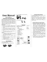
Introduction to the Video Sender
Video Sonic applies advanced 2.4GHz RF wireless technology to offer users the ability to
link all kinds of Audio and Video sources to TVs, Monitors, and Personal Computers
without wires or cables. The Video Sender is easy to completely install within minutes.
This plug-and play feature helps you to expand your freedom in your home entertainment
and enhance your home security.
Applications
• Works as the wireless remote unit for expensive A/V equipment such as IRD & DVD
• May be used as part of a wireless security system.
• Can be used as a baby sitter to watch your baby constantly from anywhere in your
home.
• Monitor and record a meeting from another room.
• Use multiple receivers for broadcasting to numerous TV sets in other rooms.
• Applicable to data transmission (optional function).
Features
• 4 selectable channels help prevent any interference and allow operation of 4 pairs
of Video Senders simultaneously.
• Easy <plug and play> installation within minutes.
• Works with all kinds of Audio and Video equipment in your home.
• Penetrates walls, floors and ceilings without damaging your home.
• Crystal - clear Audio and Video signals.

V001/05
3
GB
List of Contents
This package contains the following items:
A. This instruction sheet
B. One Transmitter (TX)
C. One Receiver (RX)
D. Two power adapters
E. Two Audio/video cables which can be either RCA connectors on both ends or RCA on
one end and SCART on the other.
F. Infrared extender

V001/05
4
GB
Controls and Features
The transmitter and receiver look alike and are identified by the logo.
Remote control antenna
Built in 2.4GHz antenna
Sends or receives Audio / Video signals.
Power ON / OFF indicator lights
Note: Must be set to the same number on
both the Transmitter and Receiver
Remote control window
Infrared passes through here to remotely
control the Audio / Video signal source.
IR extender port
Connects to the remote line-extender
mouse to remotely control A/V
signal sources (Optional)
Right audio jack (red)
Left audio jack (white)
Video jack (Yellow)
Channel Switch
Used to find optimal reception. Note: The same channel
must be selected on both the Transmitter and Receiver.
9-volt power adapter plug
(12-Volt for option)
Power ON/OFF switch
Selettore codice IR

V001/05
5
GB
Installation
Possible A/V sources are:
VCR
TV set
Digital / Analogue Satellite Receivers
Laser Disc Player
CD Player
Camcorder
Security Camera
Computer
Wireless Cable Box
Cassette Deck
Stereo Receiver
The A/V Display Units are:
TV set
Monitor
Speakers

V001/05
6
GB
Connecting the Transmitter to the A/V sources
Before connecting the Video Sender Transmitter, make sure the ON/OFF switch is in the
OFF position. Before plugging the power adapter into the Video Sender Transmitter, make
sure the power rating matches the power standard of your country. After plugging the
power adapter into the Video Sender Transmitter and the wall outlet as shown below,
turn the ON/OFF switch to the ON position and check to be sure the Power ON/OFF
indicator light is lit.
A. How to send Audio/Video from your Satellite Receiver or Laser Disc Player
(1) A/V CABLE
(2) TO WALL OUTLET
(3) COAXIAL CABLE

V001/05
7
GB
B. How to send Audio / Video from your VCR or DVD
(1) RF COMMUTER
(2) CAVO A/V CABLE
(3) TO WALL OUTLET
(4) COAXIALCABLE
TV Antenna
Set-top Box
CATV Outlet

V001/05
8
GB
Connecting the Receiver to the A/V display Units
Before connecting the Video Receiver, make sure the ON/OFF switch is in the OFF
position. Connect one set of A/V cables to the A/V jacks of the Receiver and to the A/V
jacks on the A/V input of the A/V Display Units.
There are three colors for the connectors of A/C cables. Make sure the yellow, white and
red plugs match the yellow, white and red jacks on both the transmitter and the A/V
sources correctly.
Before plugging the power adapter into the Video Receiver, make sure the power rating
matches the power standard of your country. After plugging the power adapter into the
Video Receiver and the wall outlet as shown, turn the ON/OFF switch to the ON position
and check to be sure the Power ON/OFF indicator light is lit.
A. How to connect the Receiver to your TV
(2) TO WALL OUTLET

V001/05
9
GB
Channel switch selection
The channel switch is located at the rear of the transmitter and receiver.
The Video Sender has these operation modes:
1. Set to receive a specific channel. Both the transmitter and receiver need to have the
channel switch set to the same channel. If there is interference on the
reception, change both the transmitter and receiver channel
setting to a different channel.
Example : Transmitter sends a signal to Receiver via Channel 2
T R
2. Scansion of the Channels selects you of 4 second ones at intervals. This function is
necessary when, as an example, the Receiver comes used with various television
cameras of monitoring radio (modality scansion).
Example: the receiver alternatively passes from Channel 1 to the every Channel 2 4
second ones
T 1 T 2 R
3. In order to command MHz marks them infrared from 433, the Tx and Rx IR they
must anch' be regulated to you on the same channel. Switch IR low "1", up "0"; in total
0000-1111 16 various channels IR can be selected
T R T R

V001/05
10
GB
Guideline of the antenna remote control (Optional)
In the majority of the applications, both the antennas remote control must be oriented and
vertically regarding the box main it (see Fig. 1 and 2).
Fig. 1
1. Transmitter Remote Control Antenna
2. Audio/Video Antenna
3. Receiver Remote Control Antenna
4. Transmitter
5. Receiver
If the function remote control does not work in satisfactory way, to ruotare in the first place
the antenna on the receiver being carried it in different positions (you see Fig. 3)
Fig. 2
1
5
4
3
2
2
1
4
5
3
2
2

V001/05
11
GB
If famous an improvement, to maintain the guideline corresponding. In contrary case, the
antenna of the emitter can be regulated in order to optimize the operation.
Fig. 3
1
4
5
3
2
2

V001/05
12
GB
Uso della Funzione Telecomando
1. Plug the IR Extender Mouse connector into its special jack at the side of the Video
Sender Transmitter.
2. Locate the IR sensor on the A/V source equipment you wish tocontrol. You can find
the location of the IR sensor by consulting the user's manual of the A/V source
equipment.
3. Point the IR Extender Mouse housing in the general direction of the IR sensors of
the A/V source equipment you wish to control. Cut a piece of the fastener strip
provided to secure the IR Extender Mouse in the appropriate location.
4. Position the Video Sender receiver to allow your remote control signal to strike the
IR window on the front bottom of the Receiver.
5. To perform the remote control feature, point the remote control at the front of the
Video Sender Receiver.
1. Receiver
2. IR Signal
3. Transmitter
4. Remote Control
5. Other Audio-Video Components
6. IR Signal
7. IR Extender Mouse 7. 2.4 GHz Audio-video signal
8. therefore Remote Control Signal
1
4
6
7
9
3
8
2

V001/05
13
GB
Troubleshooting
If a problem occurs, first refer to this information before you take the device for repair.
If you are unable to rectify the fault using the information given here, contact your local
dealer or service specialist.
Under no circumstances should you attempt to repair the device yourself, as this would
invalidate the warranty.
Problem Possibile cause Remedy
The transmission channels
for the transmitter/receiver
do not correspond.
Set the transmission
channel on the
transmitter/receiver
The transmission distance
is too great.
Reduce the distance.
Connecting cable.
Check the EURO-AV plug
and the cinch plug.
No picture/sound
transmission
Transmitter or receiver not
switched on.
Switch on the
transmitter or receiver
Interference Move the transmitter or
receiver a few centimetres
Microwave units and the
use of the so-called "blue
tooth function" (W LAN)
on mobile phones or
notebooks.
Change the transmission
channel on the
transmitter/receiver
Poor picture/sound quality
Switch this device off.
Infra-red module.
Check the connection and
position of the infra-red
module.
The remote control
of the signal
source does not
respond.
A wireless transmitter in the
433 MHz range (e.g. a
baby-phone) is interfering
with the transmission.
Switch this device off.

V001/05
14
GB
Technical Data
Transmitter:
1. Frequecy: 2,4 GHz – 2,4835 GHz
2. Channel: 4 selectable channels
3. Modulation : FM
Input level: Video – 1Vp-p (NTSC/PAL)
Audio – 1Vp-p (NTSC) / 3Vp-p (PAL)
Impedence: Video 75 ohm
Audio 600 ohm (NTSC) / 10 ohm (PAL)
4. Input port : jack A/V – jack linea RCA a RCA
jack A/V – jack linea RCA a SCART (optional)
5. Antenna: built in
6. Power supply: 9Vcc
Riciver:
1. Frequency: 2,4 GHz – 2,4835 GHz
2. Channel: 4 selectable channels
3. Input port: jack A/V – jack linea RCA a RCA
jack A/V – jack linea RCA a SCART (optional)
4. Antenna: built in
6. Power supply: 9Vcc

V001/05
15
GB
RECYCLING: with a view to reducing disposal of waste
electrical and electronic equipment as much as possible,
do not throw out this end of life cycle appliance together
with other unsorted municipal waste, but make use of a
recycling centre.

ITALY
Via E.Majorana 49
48022 LUGO( RA )
Tel. + 39 0545 25037
Fax.+ 39 0545 32064
Tel. Servizio Assistenza
899 899 856
E-mail: [email protected]
www.telecogroup.com
IN EUROPE:
GREAT BRITAIN - SCAN TERIEUR LTD
30, The Metro Centre, Tolpits Lane - Watford,
Herts - England - WD18 9XG
Tel. 01923 800353 - Fax 01923 220358
HOLLAND / BELGIUM - KARMAN TRADING
Lagewed 54 – 3849 PE Hierden – the Netherlands
Tel. 0341 722450 - Fax 0341 722451
e-mail: [email protected]
web site: www.karmantrading.nl
FRANCE - BLEYS JEAN-PHILIPPE
19, Rue de la Parcheminerie
18700 Aubigny sur Nere - France
Tel.02 48580367 – Fax 02 48583585
e-mail: [email protected]
ESPAÑA - NAUCCA CARAVANING, S.A.
Poligono Industrial CAN ROQUETA 2 – Calle Can Lletget,2
08202 Sabadell (Barcelona) - España
Tel. 00 34 937 457 054 - Fax. 00 34 937 254 484
e-mail: [email protected]
ÖSTERREICH – TELECO GmbH
82041 Deisenhofen - Deutshland
Tel. 0049 8031 98939 - Fax. 0049 8031 98949
e-mail: [email protected]
www.telecogroup.com
IN DEUTSHLAND
TELECO GmbH
82041 Deisenhofen -
Tel. 0049 8031 98939 - Fax. 0049 8031 98949
e-mail: [email protected]
www.telecogroup.com
Händler und Info in Ihrer Nähe (Deutschland):
01805 006857
Service für Teleco Anlagen in Deutschland:
09001000045
Foto e disegni non contrattuali - Les photos et les dessins ne sont donnés qu’à titre indicatif.
We reserve the right to make technical changes without prior notice - Fotos und Zeichnungen nicht vertraglich.
Foto’s en tekeningen niet contractueel - Fotos y planos no indicados en contrato
/

