Page is loading ...

Installation
and User’s Guide
MULTICAL® 401
www.kamstrup.com


MULTICAL® 401
English
INSTALLATION
Kamstrup A/S
Industrivej 28, Stilling, DK-8660 Skanderborg
TEL: +45 89 93 10 00 · FAX: +45 89 93 10 01
info@kamstrup.com · www.kamstrup.com

2
General conditions1.
Please read these instructions before installing the heat meter.
Kamstrup’s guarantee obligations do not apply in case of incorrect
installation.
Please note the following installation requirements:
Gland meters Flange meters only
Max. 16 bar Max. 25 bar
All types of
temperature sensors
Sensors with stainless
steel pockets only
MID designations1.1
Rated operation conditions/measuring ranges:
Calculator q: 10°C…160°C DΘ: 3K…150K
Temperature sensor pair q: 10°C…150°C DΘ: 3K…140K
Flow sensor q: 15°C…130°C
Mechanical environment: M1 (fixed installation with minimum
vibration)
Electromagnetic environment: E1 (Domestic and light industrial).
Signal cables from the meter must be separated by at least 25cm
distance to other installations.
Climatic environment: The installation shall be made in non-
condensing environments and in closed location (indoor). The
ambient temperature must be within 5…55°C.
Maintenance and repair: The heat supplier is allowed to change
communication module, battery and temperature sensor pair. The
flow sensor must never be separated from the calculator. All repairs
require a following re-verification on an accredited laboratory.
MULTICAL® 401, Type 66-W is suitable for temperature sensors
type Pt500
MULTICAL® 401, Type 66-V is suitable for temperature sensors
type Pt100
Battery for replacement: Kamstrup type 66-00-200-100

3
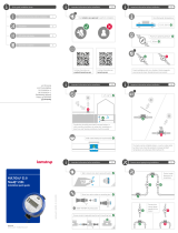
Mounting of temperature sensors2.
Temperature sensors for measuring forward and return temperatures
make out a matched pairs of sensors which must never be separated.
Usually MULTICAL® 401 is supplied with mounted temperature
sensors. The cable length must neither be shortened nor lengthened.
The sensor marked with a red sign must be mounted in the forward
pipe. The other sensor, which is marked with a blue sign, must be
mounted in the return pipe.
Pocket-mounted sensor set2.1
At an optimum, sensor pockets are mounted in tee-pipes or 45°
lateral Y-pieces. The tip of the sensor pocket must be placed in the
middle of the flow pointing against the flow direction.
Temperature sensors should be inserted into the pockets as far as
they can go. If a quick response time is required, “non-hardening”
heat conducting paste can be used.
Place the small plastic tube on the sensor cables to face the cutout
at the top of the pocket and secure the cable with the attached M4
brass screw. Fasten the screw with your fingers only. The pockets can
then be sealed with seal and sealing wire.

4
Short direct temperature sensor set2.2
The short direct sensor can be mounted in special ball valves or in
special angle tee-pipes, both with threads up to R1 and a built-in
M10 union for the short direct sensor.
For mounting in existing heating installations with standard angle
tees Kamstrup A/S can, furthermore, supply R½ and R¾ brass
nipples which fit the short direct sensors.
In addition, please refer to paragraph 4 “Mounting of flow part”,
The short direct sensor can also be fitted into all flow part variants
with a G¾ and G1 thread on the meter case.
Fasten the brass unions of the sensors lightly (approx. 4 Nm) by
means of a 12 mm face wrenth, and then seal the sensors with seal
and wire.

5
Information codes “E”3.
MULTICAL® 401 constantly monitors a series of important functions. If
a serious error occurs in the measuring system or in the installation,
an “E” appears in the left side of the display and an info-code can be
read by activating the front key, until the measuring unit in the right
side of the display shows “info”.
Info-code Description Response time
000 No irregularities -
002 Flow sensor error 48 hours
008 Temperature sensor T1 outside
measuring range
1…10 min.
004 Temperature sensor T2 outside
measuring range
1…10 min.
016 Air in flow sensor
128 Battery replacement 12 years
Short-period errors only release an “E” in the display, while the error
exists.
If the error is still present after one hour, the info-code becomes
permanent – however, not “info = 16”.

6
Mounting of flow part4.
Before mounting the flow part (flow sensor), flush the system
thoroughly and remove protection plugs/plastic membranes from the
flow sensor.
Correct flow sensor position (forward or return pipe) appears from the
front label of MULTICAL® 401.
The flow direction is indicated by an arrow on the side of the flow
sensor.
Glands and gaskets are to be mounted as shown in the above
drawing.
MULTICAL® 401 requires neither straight inlet nor outlet to meet the
Measuring Instruments Directive (MID) 2004/22/EC, OIML R75:2002,
and EN 1434:2007. Only in case of heavy flow disturbances before
the meter will a straight inlet section be necessary. We recommend to
follow the guidelines in CEN CR 13582.
To prevent cavitation the operating pressure at the flow part must
be min. 1.5 bar at qp and min. 2.5 bar at qs. This applies for
temperatures up to approx. 80°C.
When the flow part has been mounted, the water flow can be turned
on. Open the valve on the inlet side of the meter first.
The flow part must not be exposed to pressures below ambient
pressure (vacuum).
Gasket
Gasket
Tightening is approx. 4 Nm

7
Mounting of ULTRAFLOW4.1 ®
ULTRAFLOW® must not be mounted
with the plastic box facing upwards.
ULTRAFLOW® may be
turned up to max.
45° and downwards
for max. 90° in
relation to the pipe
axis.
ULTRAFLOW® can be mounted vertically,
horizontally or at any angle.

8
MULTICAL® 401 can be mounted on both sides of the flow part.
By moving the brackets MULTICAL® 401 can
be mounted on the side of the flow part, thus
reducing the built-in depth.

9
Mounting of calculator5.
Mounting5.1
MULTICAL® 401 is mounted directly on the flow part (see point 4.1
“Mounting of flow part”) or directly on a plane wall.
Use the wall bracket as a template to mark/and drill two holes of 6
mm diameter on the wall. After mounting, the calculator must be
sealed with seal and wire.

10
Power supply6.
MULTICAL® 401 can be power supplied by a built-in lithium battery, a
24 VAC internal mains module or an internal 230 VAC mains module.
The two wires from battery or mains module are to be mounted in
terminals 60 and 61 of the calculator.
The polarity has to be correct; connect the red wire to terminal no.
60 (+) and the black wire to terminal no. 61 (-).
Battery supply6.1
Connect MULTICAL® 401 to a lithium battery, D-cell. The battery is
marked with the installation year, e.g. 2008, as well as production
year.
The optimal battery life is obtained by keeping the battery
temperature below 30°C, through wall mounting.
The voltage of a lithium battery is almost constant throughout the
entire lifetime of the battery (approx. 3.65 V). Therefore, it is not
possible to determine the remaining capacity by means of voltage
measurement.
The battery cannot and must not be charged and must not be
short-circuited. Used batteries must be handed in for approved
destruction.

11
Mains modules6.2
The modules are in protection class II and are connected via a two-
wire cable (without earth) through the cable bush of the calculator
placed at the top left corner of the connection unit. Use connection
cable with an outside diameter of 5–10 mm and be aware of correct
dismantling as well as correct mounting of the cable relief.
Max. permitted fuse: 6 A.
National installation regulations must be obeyed.
Black
Red
24 VAC
A transformer must be used,
e.g. type 66-99-403, for a 24
VAC supply module.
NB! This module cannot be
supplied from 24 VDC.
Black
Red
230 VAC
This module is used for
direct mains connection.

12
Operational check7.
Carry out an operational check when the energy meter has been fully
mounted. Open the thermo-regulators and cocks in order to establish
a water flow through the heating system. Activate the push-button
on MULTICAL® 401 and check that the display values of temperatures
and water flow are probable.
Electrical connection8.
The polarity of the temperature sensors T1 and T2 is unimportant.
Terminal no. Standard heat
+ 60 Supply (red)
- 61 Supply (black)
T1 5 - 6 Sensor in flow (red)
T2 7 - 8 Sensor in return (blue)

13
Plug-in modules9.
MULTICAL® 401 can be retrofitted with a series of extra functions
in the form of plug-in modules. Below is a brief description of the
individual modules.
Data/pulsindgange9.1
The data terminals are used
for e.g. connecting a PC or
a MULTITERM hand-held
terminal via an external
reading plug which is
connected as shown below.
65 - 66
67 - 68
Input A
Input B
f < 0,5 Hz
f < 0,5 Hz
62
63
64
Brown
White
Green
The signal is passive and galvanically separated through
optocouplers. Conversion to RS232 level requires the connection of
data cable 66-99-106 with above connections.
The pulse inputs can be used for connecting water meters. Please
note the max. pulse frequency and the correct pulse coding (l/pulse),
which are selected by means of the FF and GG configuration.

14
Data/pulse output9.2
The pulse output is used e.g. for remote counting of energy.
1 pulse is emitted per display count for energy, e.g.
1 pulse/kWh, when MULTICAL® 401 is programmed
for a flow sensor of qp 1.5 m3/h.
16 - 17 CE Energi Config. FF must be
set to“94”-“96” and
GG to “00”
I < 10 mA
U < 30 V
Pulse duration
1 ms/30 ms/0.1 sec.

15
M-Bus/pulse inputs9.3
M-Bus module can be mounted in star, ring, or bus topology.
M-Bus modules are available in two versions
- supporting primary addressing
- supporting primary and secondary addressing
The M-Bus
network is to be
connected to the
terminals 24 and
25. The polarity is
unimportant.
M-Bus module
is available with
pulse inputs.
Radio/pulse inputs9.4
The radio module is used for wireless communication via licence-
free radio frequency, and is supplied for either internal or external
antenna.
For further details on radio, please refer to Technical Description for
radio (5512-013 GB).
The pulse inputs in this module is identical with the earlier
described.

5512-109 GB/04.2008 Rev. E1
16

Measuring energy
MULTICAL
®
401 heat meter functions in the following
manner:
The water meter registers the quantity [m ] of district heating
water that circulates in the heating installation.
The temperature sensors placed in the flow and return pipes
register the degree of cooling in the heating installation, i.e. the
difference between the inlet temperature and the outlet
temperature.
Using this information, MULTICAL
®
401 is able to calculate
the amount of energy consumed.
Readings in the display
When you press the front key and hold it down for one
second, a new reading will be displayed.
150 seconds after the key has been activated, the display will
return to consumed energy, which is the default.
MULTICAL® 401
www.kamstrup.com
NB! The arrow ‟ indicates the
type of measurement displayed.
The unit can be seen to the right
in the display.
USER GUIDE
0200
M08
Meter in Flow pipe
DN15 PN16 G¾B*110 mm
qi: 0.006 m³/h
Type: 66W0001219
1234569/2008S/N:
32119Prog:
1Con:
qs: 1.2 m³/h
q: 15...130 °C
IP54 (5-55°C)
P: 0.04 bar
SW: SE 3.01
Pt500 - EN 60751
: 10°C...160°C
: 3K...150K
qp: 0.6 m³/h
Class: 2 (E1,M1)
DK-0200-MI004-001
Non-cond/Closed
123456
2008
5512-109 GB/04.2008 Rev. E1

Consumed
energy in
kWh, MWh or GJ
Consumed
district
heating water
Number of hours
MULTICAL® 401
has been in
operation
Current flow
temperature
Current return
temperature
Information code
NB! If this number is
larger than "000",
please contact your
heat supplier.
Current flow rate
Peak power
Current heat
power
Current cooling
Primary displays
Additional displays
To change between primary and underlying displays, press the
button for a minimum of 3 seconds.
Customer number Software Edition Display segment test
5512-109 GB/04.2008 Rev. E1
/