Page is loading ...

MULTICAL® 801 &
ULTRAFLOW® 54 (H)
Kamstrup A/S · Industrivej 28, Stilling · DK-8660 Skanderborg · T: +45 89 93 10 00 · [email protected] · kamstrup.com
Installation and User Guide

2 Kamstrup A/S • 55121851_A2_GB_07.2020
MULTICAL® 801 & ULTRAFLOW® 54 (H)
Energy metering
MULTICAL® 801 functions in the following way:
The flow sensor registrates how many m³ (cubic metres) of district heating
water are circulating through the heating system.
The temperature sensors, placed in inlet and outlet flow pipes, register
cooling, i.e. the difference between the input and output temperatures.
MULTICAL® 801 calculates the consumed amount of energy based on the
district heating water volume and cooling.
Readings in the display
When the upper front key is activated, a new reading appears.
The lower front key is used to show historical readings and average
values.
4 minutes after the front key has been activated reading of consumed
energy will automatically appear.

MULTICAL® 801 &
ULTRAFLOW® 54 (H)
Installation Guide
Kamstrup A/S · Industrivej 28, Stilling · DK-8660 Skanderborg · T: +45 89 93 10 00 · [email protected] · kamstrup.com

4 Kamstrup A/S • 55121851_A2_GB_07.2020
MULTICAL® 801 & ULTRAFLOW® 54 (H)
Information
Rated operating conditions/measuring ranges
Calculator q: 2 °C…180 °C DΘ: 3K…170K
Temperature sensor pair q: 10 °C…150 °C DΘ: 3K…140K
Flow sensor q: 15 °C…130 °C
Mechanical environment
M1 (fixed installation with minimum vibration).
M2 (considerable or high degree of vibration and impact - flow meter only).
Electromagnetic environment
E1 and E2 (domestic/light industry and industry). Signal cables from the
meter must be separated by at least 25 cm distance to other installations.
Climatic environment
The installation shall be made in non-condensing environments and in
closed location (indoor). The ambient temperature must be within 5…55 °C.
Maintenance and repair
The heat supplier is allowed to change communication module, back-up
battery, calculator, temperature sensor pair and flow sensor. Calculator,
temperature sensor pair and flow sensor are separately verified and
can, therefore, be separately exchanched. All repairs require a following
re-verification in an accredited laboratory.
MULTICAL® 801, type 67-G/L must be connected to temperature sensors
type Pt500.
MULTICAL® 801, type 67-F/K must be connected to temperature sensors
type Pt100.
MULTICAL® 801 can be connected to flow sensor type ULTRAFLOW®,
electronic pick-up unit, flow sensor with reed switch output or a flow sensor
with 24 V active pulse output.
Irrespective of flow sensor type, ”pulses/litres” must be identical in flow
sensor and calculator.
Battery for replacement
Kamstrup type 6699-619 (2 x AA-cell).

5Kamstrup A/S • 55121851_A2_GB_07.2020
MULTICAL® 801 & ULTRAFLOW® 54 (H)
Contents
1 General information 6
2 Mounting of temperature sensors 7
2.1 Short direct sensor (DS) 7
2.2 Pocket sensor (PL) 8
3 Mounting of flow sensor 9
3.1 Mounting of couplings and short direct sensor mounted in
ULTRAFLOW® flow part 9
3.2 Mounting of ULTRAFLOW® 54 (H) (separately mounted) 10
3.3 Installation examples (MULTICAL® mounted on ULTRAFLOW® 54 (H)) 10
3.4 Mounting of angle fitting 12
4 Mounting of calculator 14
4.1 MULTICAL® 801 front dimensions 14
4.2 MULTICAL® 801 installation dimensions 14
5 Power supply 14
5.1 Backup battery 14
6 Operational check 15
7 Electrical connection 15
7.1 Examples of connections 16
8 Data modules 18
8.1 GSM/GPRS module (GSM6H), type 67-0Z 18
8.2 3G GSM/GPRS module (GSM8H), type 67-0U 18
8.3 Ethernet/IP module (IP201), type 67-0T 19
8.4 M-Bus, type 67-00-20/67-00-27/67-00-29/67-0V/67-0P/67-0Q 19
8.5 Radio + pulse inputs, type 67-00-21/67-0W 19
8.6 Prog. data logger + RTC + 4…20 mA inputs + pulse inputs, type 67-00-22 20
8.7 Lon Works, type 67-00-24/67-0Y 20
8.8 Wireless M-Bus, type 67-00-30/67-00-31/67-00-35/67-00-38 20
8.9 ZigBee® + pulse inputs, type 67-00-60 20
8.10 Metasys N2 + pulse inputs, type 67-00-62 21
8.11 SIOX module (Auto detect Baud rate), type 67-00-64/67-0M 21
8.12 BACnet® + pulse inputs, type 67-00-66 21
8.13 Modbus RS485 RTU Slave Module + pulse inputs, type 67-00-67 22
8.14 High Power Radio Router + 2 pulse inputs (VA, VB), type 67-00-84 22
8.15 Module overview 23
8.16 Insertion of modules 24
9 Information codes ”INFO” 25
10 Terminal Overview 26

6 Kamstrup A/S • 55121851_A2_GB_07.2020
MULTICAL® 801 & ULTRAFLOW® 54 (H)
1 General information
Read this guide before installing the meter.
Kamstrup’s guarantee obligations do not apply in case of incorrect
mounting.
Please note that the following installation conditions must be obeyed:
- Pressure stage ULTRAFLOW®: PN16/PN25, see marking. Marking
of flow part does not cover included
accessories.
- Pressure stage Kamstrup
sensor set type DS: PN16/PN25
- Pressure stage Kamstrup
pocket sensors type PL: PN16/PN25
Please make sure that MULTICAL® 801 is connected to correct voltage, either
230 VAC or 24 VAC. See the marking at terminals 27 and 28 at the bottom
left.
MULTICAL® 801 must be sealed with seal and wire or a sealing label after
mounting.

7Kamstrup A/S • 55121851_A2_GB_07.2020
MULTICAL® 801 & ULTRAFLOW® 54 (H)
2 Mounting of temperature sensors
The temperature sensors used for measuring inlet and outlet temperatures
respectively, constitute a matched sensor pair, which must never be
separated. According to EN 1434/OIML R75, the cable length must not be
changed. Should replacement be necessary, both sensors must be replaced.
The sensor marked with a red sign is to be installed in the inlet pipe. The
other sensor, marked with a blue sign, is to be installed in the outlet pipe. For
mounting in the calculator, see the paragraph ”Electrical connection”.
Note: The sensor cables must neither be exposed to jerking nor pulling.
Please be aware of this when binding the cables, and be careful not to
pull the binders unnecessarily tight as this may damage the cables.
Please also note that temperature sensors must be mounted from
below in cooling and heat/cooling installations.
2.1 Short direct sensor (DS)
The short, direct sensors up to DN25
can be mounted in special ball
valves with built-in M 10 socket for
the short direct sensor. They can
also be mounted in installations
with standard tee-pieces. Kamstrup
A/S can supply R½ and R¾ brass
nipples that fit the short direct
sensors. The short direct sensor can
also be mounted directly in selected
flow sensors from Kamstrup A/S.
Fasten the sensors’ brass unions
lightly (approx. 4 Nm) using a 12 mm
face wrench, and seal the sensors
with seal and locking wire.

8 Kamstrup A/S • 55121851_A2_GB_07.2020
MULTICAL® 801 & ULTRAFLOW® 54 (H)
2.2 Pocket sensor (PL)
The sensor pockets can be mounted
in e.g. a welding sleeve or in a 45°
lateral Y-piece. The tip of the sensor
pocket must be placed in the middle
of the flow. Push the temperature
sensors as deep as possible into the
pockets. If a short response time is
required, “non-hardening” thermally
conductive paste can be used. Push
the plastic sleeve on the sensor
cable into the sensor pocket and
secure the cable by means of the
enclosed M4 sealing screw. Fasten
the screw with your fingers only.
Seal the pockets using seal and
locking wire.
A
A
B
B
B
B
SECTION
B-B
SCALE
1 : 1

9Kamstrup A/S • 55121851_A2_GB_07.2020
MULTICAL® 801 & ULTRAFLOW® 54 (H)
3 Mounting of flow sensor
Prior to installation of the flow sensor, the system should be flushed and
protection plugs/plastic diaphragms removed from the flow sensor.
Correct flow sensor position (inlet or outlet pipe) appears from the front label
of the MULTICAL® 801. The flow direction is indicated by an arrow on the flow
sensor.
3.1 Mounting of couplings and short direct sensor mounted in
ULTRAFLOW® flow part
The flow sensor can be used in
connection with either PN16 or PN25
(see marking).
Any provided blind plug, extension
and gland can be used with both
PN16 and PN25.
In connection with flow sensors
with the nominal dimensions
G¾Bx110 mm and G1Bx110 mm,
it must be checked if the thread
run-out is sufficient.
Couplings and gaskets are mounted
as shown in the figure. Make sure to
position the gasket correctly in the
recess of the gland as shown in the
details excerpt in the figure.
Gasket
Tightening
app. 4 Nm
12 mm
Couplings and gaskets are mounted as shown in the above figures.

10 Kamstrup A/S • 55121851_A2_GB_07.2020
MULTICAL® 801 & ULTRAFLOW® 54 (H)
3.2 Mounting of ULTRAFLOW® 54 (H) (separately mounted)
ULTRAFLOW® can be mounted
vertically, horizontally or at an angle.
At vertical mounting, it may be of
advantage to pivot ULTRAFLOW®
±360° around the pipe axis.
90° 90°
The electronics/plastic box should
be placed on the side (at horizontal
mounting).
3.3 Installation examples (MULTICAL® mounted on ULTRAFLOW® 54 (H))
MULTICAL® 801 can be mounted directly on ULTRAFLOW® 54 (H) by means of
fitting 3026-857. Mount fitting 3026-857 on the back of MULTICAL® 801 as
shown in the figure below.
ABC
A The top of the fitting is led into a guide rail on the back of MULTICAL® 801
and is pushed up to the edge.
B The two hooks at the bottom of the fitting are pressed into the shown
locks with the fingers. When a “click” is heard, the fitting is locked.
C MULTICAL® 801 can now be mounted directly on ULTRAFLOW® 54 (H).

11Kamstrup A/S • 55121851_A2_GB_07.2020
MULTICAL® 801 & ULTRAFLOW® 54 (H)
Installation on an ascending pipe
When installing ULTRAFLOW® on
an ascending pipe, it can be of
advantage to turn ULTRAFLOW® ±360°
around the pipe axis to optimise the
readability of the MULTICAL® display
at direct mounting of MULTICAL® on
ULTRAFLOW®.
Installation at eye level or higher
In case of installations above eye
level, it can be of advantage to
turn ULTRAFLOW® -45° downwards
to optimise the readability of the
MULTICAL® display at direct mounting of
MULTICAL® on ULTRAFLOW®.
45°
Installation at ground level
In case of installations at ground
level, it can be of advantage to mount
MULTICAL® directly on ULTRAFLOW®
by means of the provided angle
fitting (“3.4 Mounting of angle fitting”
page 12). ULTRAFLOW® can be
turned -45° downwards to optimise the
readability of the MULTICAL® display.
45°

12 Kamstrup A/S • 55121851_A2_GB_07.2020
MULTICAL® 801 & ULTRAFLOW® 54 (H)
3.4 Mounting of angle fitting
A
B
C1C2
A Place the angle fitting on the lower edge of the plastic casing. Both sides
of the plastic casing can be used.
B Turn the angle fitting, and place it on the plastic casing.
C Lock the click lock by finger push (C1). The lock can be reopened by
finger push and pull (C2).

13Kamstrup A/S • 55121851_A2_GB_07.2020
MULTICAL® 801 & ULTRAFLOW® 54 (H)
Straight inlet: ULTRAFLOW® requires neither straight inlet nor straight
outlet to meet the Measuring Instruments Directive 2014/32/EU and EN
1434:2015. A straight inlet section will only be necessary in case of heavy
flow disturbances before the meter. We recommend to follow the guidelines
of CEN CR 13582.
A Recommended position.
B Recommended position.
C Unacceptable position due to
risk of air build-up.
D Acceptable position in closed
systems.
E Ought not to be placed
immediately after a valve, with
the exception of block valves
(ball valve type) which must be
fully open when not used for
blocking.
F Ought not to be placed
immediately before or after a
pump.
G Ought not to be placed
immediately after a double bend
in two planes.
E
F
G
A
BC
D
In order to prevent cavitation the back pressure (the pressure at the flow
sensor outlet) at ULTRAFLOW® must be min. 1.0 bar at qp and min. 2.0 bar at
qs. This applies to temperatures up to approx. 80 °C. ULTRAFLOW® must not
be exposed to lower pressure than the ambient pressure (vacuum).

14 Kamstrup A/S • 55121851_A2_GB_07.2020
MULTICAL® 801 & ULTRAFLOW® 54 (H)
4 Mounting of calculator
4.1 MULTICAL® 801
front dimensions
4.2 MULTICAL® 801
installation dimensions
Prog:
Con:
Class:
Meter in flow pipe
Heat meter / 4
W
∆Θ:3K…170K
Pt 500-EN 60751
: 2°C…180°C
θ
Type: 67F0002A1219
6044052/200
8
33119119
21200040300
E2, M1
Imp/l:
qp:
100
Non-condensing/Closed
IP67 (5-55°C)
DK-0200
MI004-009
S/N:
1,5 m³/h
6044052
MULTICAL®
801
168
184
210
140
80,5
104,5 64
5 Power supply
MULTICAL® 801 is power supplied by 24 VAC or 230 VAC.
5.1 Backup battery
MULTICAL® 801 includes a backup battery, which ensures that all relevant
measurements continue during power failure.
The battery ought to be replaced after 10 years’ normal operation, or after 1
year without mains connection.
The type number of the backup battery is 66-99-619.
The voltage of a lithium battery is almost constant throughout the whole
lifetime of the battery (approx. 3.65 V). Therefore, it is not possible to
determine the remaining capacity by measuring the voltage.
The battery cannot and must not be charged and must not be
short-circuited. Used batteries must be handed in for approved destruction,
e.g. at Kamstrup.

15Kamstrup A/S • 55121851_A2_GB_07.2020
MULTICAL® 801 & ULTRAFLOW® 54 (H)
6 Operational check
Carry out an operational check when the energy meter has been fully
mounted. Open thermo-regulators and cocks in order to establish a water
flow through the heating system. Activate the upper push button on the
MULTICAL® 801 and check that the display values for temperature and water
flow are reliable.
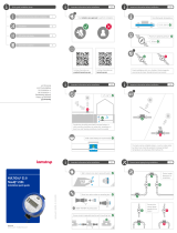
7 Electrical connection
The temperature sensors are
mounted in the terminals of the
calculator as shown above. Jumpers
are used when mounting 2-wire
sensors.
In connection with flow sensors
V1 and V2, the below-mentioned
colours are used for connection of
ULTRAFLOW® and electronic pick-up
units.
Flow sensors with Reed switch
output must be connected
to terminals 11-10 and 11-69,
respectively.
V1 V2
- 11 11 Blue
+ 9 9 Red
SIG 10 69 Yellow
4-wire
51 51A 52A 52 3 7 8 4 1 5 6 2
T3 T2 T1
Pt Pt Pt
2-wire
51 51A 52A 52 3 7 8 4 1 5 6 2
T3 T2 T1
Pt Pt Pt

16 Kamstrup A/S • 55121851_A2_GB_07.2020
MULTICAL® 801 & ULTRAFLOW® 54 (H)
Terminal
No.
Standard
measurement of
heat and cooling
Heat
measurement and
leak surveillance
Energy
measurement
in open systems
T1 1–5–6–2 Sensor in inlet
pipe (red)
Sensor in inlet
pipe (red)
Sensor in inlet
pipe (red)
T2 3–7–8–4 Sensor in outlet
pipe (blue)
Sensor in outlet
pipe (blue)
Sensor in outlet
pipe (blue)
V1 11–9–10 Flow sensor in
inlet or outlet pipe
Flow sensor in
inlet pipe
Flow sensor in
inlet pipe
V2 11–9–69 - Flow sensor in
outlet flow pipe
Flow sensor in
outlet pipe
T3 51–51A–
52A–52
-Tank/heat exchanger
temperature
Reference sensor
(grey)
Other makes of flow sensors are usually connected to terminals 10B and 11B.
7.1 Examples of connections
The active pulse output is direct
connected to the not galvanically
separated flow sensor input. This
permits a cable length of up to 10 m
between flow sensor and calculator.
ULTRAFLOW® 54/34, DN15-125
YELLOW
BLUE
RED MULTICAL® 801
GND
+3.6 V
10K
Auxiliary voltage from terminals 97A
and 98A is added to the passive
contact output on terminals 10A and
11A before the signal is connected to
the galvanically separated flow sensor
input. This permits a cable length of
up to 100 m between flow sensor and
calculator.
ULTRAFLOW® 54, DN150-250
6699-903 & 6699-615/6699-624
MULTICAL® 801
10B
11B
97A
98A
56K2
11A
10A
9A
The active pulse output of the flow
sensor is connected to the galvanically
separated flow sensor input directly.
This permits a cable length of up
to 100 m between flow sensor and
calculator.
SONOFLO/MAGFLO MkIII MULTICAL® 801
10B (69B)
11B (79B)
V1 (V2)
50
51
52
PE

17Kamstrup A/S • 55121851_A2_GB_07.2020
MULTICAL® 801 & ULTRAFLOW® 54 (H)
The active pulse output of the flow
sensor is connected to the galvanically
separated flow sensor input directly.
This permits a cable length of up
to 100 m between flow sensor and
calculator.
MAGFLO Mk IV MULTICAL® 801
56
56
56
56
10B (69B)
11B (79B)
V1 (V2)
The active pulse output is direct
connected to the galvanically
separated flow sensor input. This
permits a cable length of up to 100 m
between flow sensor and calculator.
SITRANS F
MAGFLO
MULTICAL® 801
10B
11B
69B
79B
V1
V2
44
45
46
57
58
Heat energy Cooling energy
Same DΘ polarity E2 = V2 (T1-T2)k E1 = V1 (T1-T2)k
Changed DΘ polarity E2 = V2 (T1-T2)k E3 = V1 (T2-T1)k
Auxiliary voltage from E+ and E- is
added to the passive contact output
P of the flow sensor before the signal
is connected to the galvanically
separated flow sensor input. This
permits a cable length of up to 100 m
between flow sensor and calculator.
KROHNE
ALTOFLUX MULTICAL® 801
V1 (V2)
10B (69B)
11B (79B)
P
P
E+
E-
PE
The active pulse output of the flow
sensor is connected to the galvanically
separated flow sensor input directly.
This permits a cable length of up
to 100 m between flow sensor and
calculator.
BAILEY FISCHER & PORTER
COPA/MAG-XE
MULTICAL® 801
10B (69B)
11B (79B)
V1 (V2)
10
9
V3
V1
PEPE
24V+ (V9)
(V8)
COPA/MAG-XM/CM
The passive contact output of the
flow sensor on terminals 56 and
57 is connected directly to the flow
sensor input which is not galvanically
separated. This permits a cable length
of max. 10-20 m between flow meter
and calculator.
MULTICAL® 801
SITRANS
57
56
11
9
10

18 Kamstrup A/S • 55121851_A2_GB_07.2020
MULTICAL® 801 & ULTRAFLOW® 54 (H)
Auxiliary voltage from terminals 97A
and 98A is added to the passive
contact output of the flow sensor
on terminals 56 and 57 before the
signal is connected to the galvanically
separated flow sensor input. This
permits a cable length of up to 100 m
between flow sensor and calculator.
MULTICAL® 801
SITRANS
57
56
10B
11B
97A
98A
Auxiliary voltage from terminals 97A
and 98A is added to the passive
contact output on terminals 24 and
25 before the signal is connected to
the galvanically separated flow sensor
input. This permits a cable length of
up to 100 m between flow sensor and
calculator.
MULTICAL® 801
E + H Promag
25
24
10B
11B
97A
98A
8 Data modules
8.1 GSM/GPRS module (GSM6H), type 67-0Z
The GSM/GPRS module functions as transparent communication path
between reading software and MULTICAL® 801 and is used for data reading.
The module includes an external dual-band GSM antenna which must always
be used. The module itself includes a line of light emitting diodes indicating
signal strength which are very useful during installation.
Further details about the GSM/GPRS module appear from data sheet (DK:
5810627, GB: 5810628, DE: 5810629, SE: 5810630).
8.2 3G GSM/GPRS module (GSM8H), type 67-0U
Like GSM6H this module functions as transparent communication path
between reading software and MULTICAL® 801 and is used for data reading.
However, this module supports both 2G (GSM/GPRS) and 3G (UMTS) which
makes it applicable in areas with 3G coverage only.
The module requires an external Antenna, which covers both 900 MHz,
1800 MHz and 2100 MHz.
The module itself is fitted with a line of light emitting diodes indicating
signal strength which are very useful during installation. Furthermore, it
is indicated whether the module is connected to a 2G or a 3G network.
Additional details about the 3G module appear from data sheet (DK:
58101057, GB: 58101058, DE: 58101059, FI: 58101061, SE: 58101060).

19Kamstrup A/S • 55121851_A2_GB_07.2020
MULTICAL® 801 & ULTRAFLOW® 54 (H)
8.3 Ethernet/IP module (IP201), type 67-0T
The IP module functions as transparent communication between reading
software and MULTICAL® 801 and is used for data reading. The module
supports both dynamic and static addressing. This is specified in the order
or selected during subsequent configuration. The module has no built-in
security and must, therefore, always be used in connection with a firewall
or NAT.
Further details appear from the data sheet (DK: 5810541, GB: 5810542, DE:
5810543, SE: 5810544).
8.4 M-Bus, type 67-00-20/67-00-27/67-00-29/67-0V/67-0P/67-0Q
M-Bus can be mounted in star, ring or bus topology. Depending on the power
supply of the M-Bus Master as well as the total cable resistance, up to
250 meters can be connected.
Cable resistance < 29 Ohm
Cable capacity < 180 nF
The M-Bus network is to be
connected to terminals 24 and 25.
The polarity is unimportant. M-Bus
is supplied with pulse inputs (at
module 1 only which is located
nearest the terminals).
Input A Input B
65 66 67 68
25 24
M-BUS
A
(+)
(-)
(+)
B
(-)
680K
680K
11K2
11K2
11K2
11K2
0.1 µ
0.1 µ
8.5 Radio + pulse inputs,
type 67-00-21/67-0W
The radio module is used for
wireless communication via a
license-free radio frequency and
is available for internal or external
antenna.
The pulse inputs in this module are
identical with the ones described
earlier.

20 Kamstrup A/S • 55121851_A2_GB_07.2020
MULTICAL® 801 & ULTRAFLOW® 54 (H)
8.6 Prog. data logger + RTC + 4…20 mA inputs + pulse inputs,
type 67-00-22
The module has connection possibility for two pressure transmitters on
terminals 57, 58 and 59 and can be adjusted for current reading or pressure
range 6, 10 or 16 bar.
The module is prepared for remote reading, data from meter/module being
transferred to the system software via the external GSM/GPRS modem
connected on terminals 62, 63 and 64.
Furthermore, the module has two extra pulse inputs, VA and VB.
The module must be powered by 24 VAC.
8.7 Lon Works, type 67-00-24/67-0Y
Re mounting of Lon Works type 67-00-24, see installation guide 5512-396
(DK) or 5512-403 (GB).
8.8 Wireless M-Bus, type 67-00-30/67-00-31/67-00-35/67-00-38
The radio module has been designed to form part of the hand-held Wireless
M-Bus Reader systems of Kamstrup A/S at license-free radio frequency
(868 MHz).
The module fulfils the C-mode specifications of prEN13757-4 and can thus
form part of other systems using Wireless M-Bus C-mode communication.
The radio module comes with internal antenna and external antenna
connection as well as two pulse inputs, which are identical with the
previously described pulse inputs.
The Wireless M-Bus radio transmitter is switched off on dispatch from the
factory. It turns on automatically when one litre of water has run through the
meter. The radio transmitter can also be switched on by means of a forced
dial-up to the meter (keep both front keys pressed for approx. 5 s. until CALL
is displayed).
8.9 ZigBee® + pulse inputs, type 67-00-60
The ZigBee® module is used for wireless communication and can form part
of a remote reading system, in which several units can communicate with
each other.
The pulse inputs of this module are identical with the previously described
pulse inputs.
The ZigBee® module requires mains supply.
/