Page is loading ...

MULTICAL® 402
Kmsrup A/S · Indusrivej 28, Silling · DK-8660 Sknderborg · T: +45 89 93 10 00 · info@kmsrup.com · kmsrup.com
Installation and User Guide

2 Kamstrup A/S • 5512772_D3_GB_03.2017
MULTICAL® 402
Energy Mesurement
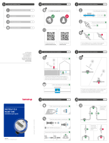
MULTICAL® 402 functions in the following wy:
The flow meter registers the mount of district heting wter in m³ (cubic
metres) circulting through the heting system.
The temperture sensors plced in inlet nd outlet pipes register the
cooling, i.e. the difference between input nd output tempertures.
MULTICAL® 402 clcultes consumed energy bsed on volume of district
heting wter nd cooling.
Redings
When the top front key is ctivted, new reding ppers.
The lower front key displys historicl redings nd verge vlues.
Four min. fter the ltest ctivtion of the front key the meter utomticlly
switches to consumed energy.

MULTICAL® 402
Kmsrup A/S · Indusrivej 28, Silling · DK-8660 Sknderborg · T: +45 89 93 10 00 · info@kmsrup.com · kmsrup.com
Installation Guide

4 Kamstrup A/S • 5512772_D3_GB_03.2017
MULTICAL® 402
MID designtions
Permissible operting conditions / mesuring rnges
Clcultor q: 2 °C…160 °C DΘ: 3K…150K
Temperture sensor set q: 10 °C…150 °C DΘ: 3K…140K
Flow sensor (het meter) q: 15 °C…130 °C
Also vilble s cooling meter with temperture rnge 2...50 °C or s
combined het/cooling meter with temperture rnge 2...130 °C, without MID
pprovl however.
Mechnicl environment
M1 (fixed instlltion with minimum vibrtion).
Electromgnetic environment
E1 (housing/light industry). The meter’s control cbles must be drwn t min.
25 cm distnce to other instlltions.
Climtic environment
Must be instlled in environments with non-condensing humidity s well
s in closed loctions (indoors). The mbient temperture must be within
5…55 °C.
Mintennce nd repir
The district heting supplier cn replce communiction module, bttery
nd temperture sensor set. The flow sensor must not be seprted from the
clcultor
Other repirs require subsequent reverifiction in n ccredited lbortory.
MULTICAL® 402, type 402-W nd 402-T must be connected to temperture
sensor set type Pt500.
MULTICAL® 402, type 402-V must be connected to temperture sensor set
type Pt100.
Bttery for replcement
Kmstrup type 402-000-2000-000 (D-cell) or 402-000-1000-000
(2 x AA-cells).

5Kamstrup A/S • 5512772_D3_GB_03.2017
MULTICAL® 402
Contents
1 Generl informtion 6
2 Mounting of temperture
sensors 6
2.1 Pocket sensor set 7
2.2 Short direct sensor set 8
3 Informtion codes ”INFO” 8
4 Mounting of flow sensor 9
4.1 Mounting of glnds nd
short direct sensor mounted
in MULTICAL® 402 flow prt 9
4.2 Mounting of MULTICAL® 402 11
4.3 Instlltion exmples 12
5 Mounting the clcultor 13
5.1 Compct mounting 13
5.2 Wll mounting 14
5.3 Mounting position of
clcultor 15
6 Power supply 15
6.1 Bttery supply 16
6.2 Mins modules 16
7 Testing the function 17
8 Electricl connection 17
9 Plug-in modules 18
9.1 Pulse inputs 18
9.2 Pulse outputs 18
9.3 Dt + pulse inputs,
type 402-0-10 19
9.4 Dt + pulse outputs,
type 402-0-11 19
9.5 M-Bus + pulse inputs,
type 402-0-20 20
9.6 M-Bus + pulse outputs,
type 402-0-21 20
9.7 M-Bus module with
MULTICAL® III dt
pckge + pulse inputs,
type 402-0-29 21
9.8 Wireless M-Bus,
type 402-0-30 nd
402-0-35 21
9.9 Wireless M-Bus,
type 402-0-31 22
9.10 Wireless M-Bus,
type 402-0-37 23
9.11 Wireless M-Bus,
type 402-0-38 24
9.12 Rdio, type 402-0-40
nd 402-0-41 25
9.13 Rdio+ pulse inputs,
type 402-0-42 nd
402-0-44 25
9.14 Rdio+ pulse outputs, type
402-0-43 nd 402-0-45 26
9.15 Module overview 27
10 Setup vi front keys 28

6 Kamstrup A/S • 5512772_D3_GB_03.2017
MULTICAL® 402
1 Generl informtion
Red this guide before instlling the meter.
In cse of incorrect mounting Kmstrup’s gurntee obligtions no longer
pply.
Plese note tht the following instlltion conditions must be obeyed:
- Pressure stge: PN16/PN25, see mrking. The flow
sensor mrking does not pply to
enclosed ccessories
- Pressure stge, Kmstrup
sensor set type DS: PN16
- Pressure stge, Kmstrup
stinless steel pockets: PN25
At medium tempertures bove 90 °C in flow sensor, use of flnge meters is
recommended, nd the clcultor should be wll-mounted.
2 Mounting of temperture sensors
The temperture sensors used to mesure inlet nd outlet tempertures re
mtched sensor set tht must never be seprted.
MULTICAL® 402 is by defult supplied with mounted temperture sensors.
According to EN 1434 the cble length must not be chnged. If necessry,
sensors must lwys be replced in pirs.
One sensor is mrked with red sign nd must be instlled in the inlet pipe.
The other sensor is mrked with blue sign nd must be instlled in the
outlet pipe (see prgrph 8, pge 17).
Note: The sensor cbles must not be pulled. Be wre of this in cse of
binding the cbles.

7Kamstrup A/S • 5512772_D3_GB_03.2017
MULTICAL® 402
2.1 Pocket sensor set
Preferbly, sensor pockets must
be mounted in tee-pieces or in
45° lterl Y-pieces. The tip of the
sensor pocket must point ginst
the flow direction nd be plced in
the middle of the wter flow.
Temperture sensors should be
inserted to the bottom of the
pockets. If short response time
is required, “non-hrdening” het
conducting pste cn be used.
Push the plstic sleeve on the
sensor cble into the sensor pocket
nd secure the cble with the
enclosed M4 seling screw. Fsten
the screw with your fingers only.
Sel the pockets using sel nd
locking wire.
*
*
Pakning
DETAIL
* Pakning
*
DETAIL
A
A
SECTION
A-A
SCALE
1 : 1

8 Kamstrup A/S • 5512772_D3_GB_03.2017
MULTICAL® 402
2.2 Short direct sensor set
Short direct sensors cn be mounted
in specil bll vlves or in specil tee-
pipes, both with threds up to R1 nd
built-in M10 union for the short direct
sensor.
For mounting in existing heting
instlltions with stndrd ngle tees
Kmstrup A/S cn supply R½ nd R¾
brss nipples fitting the short direct
sensors.
Short direct sensors cn lso be
fitted directly into ll Kmstrup’s
ULTRAFLOW® vrints with G¾ nd
G1 threds on the meter cse. Fsten
the brss unions of the sensors lightly
(pprox. 4 Nm) using 12 mm fce
wrench nd sel the sensors with sel
nd locking wire.
3 Informtion codes ”INFO”
MULTICAL® 402 constntly monitors number of importnt functions. If
there is serious error in the mesuring system or instlltion, flshing
“INFO” is displyed, nd n info code cn be red by ctivting the top front
key until the mesuring unit displys “INFO”. The info code is visible s
long s the error exists, unless the meter hs been specilly configured for
”mnul reset of info codes”. When n info code hs existed for n hour, it is
sved in the info log.

9Kamstrup A/S • 5512772_D3_GB_03.2017
MULTICAL® 402
Info Code Description Response time
0 No irregulrities -
1 Supply voltge hs been interrupted -
8 Temperture sensor T1 outside mesuring
rnge
< 30 sec.
4 Temperture sensor T2 outside mesuring
rnge
< 30 sec.
4096 Flow sensor V1, signl too wek (ir) < 30 sec.
16384 Flow sensor with wrong flow direction < 30 sec.
If severl info codes pper t time, the sum of the info codes is displyed.
If e.g. both temperture sensors re outside mesuring rnge, info code 12 is
displyed.
4 Mounting of flow sensor
Prior to instlltion of the flow sensor, the system should be flushed nd
protection plugs/plstic diphrgms removed from the flow sensor.
Correct flow sensor position (inlet or outlet pipe) ppers from the front lbel
of the MULTICAL® 402. The flow direction is indicted by n rrow on the side
of the flow sensor.
4.1 Mounting of glnds nd short direct sensor mounted in
MULTICAL® 402 flow prt
The short direct sensor from
Kmstrup cn only be mounted in
PN16 instlltions. The blind plug
mounted in the MULITCAL® 402 flow
prt cn be used in connection with
both PN16 nd PN25.
The flow meter cn be used in both
PN16 nd PN25 nd cn be supplied
mrked either PN16 or PN25 s
desired.
Gsket
Tightening
pprox. 4 Nm
Gsket
10 mm

10 Kamstrup A/S • 5512772_D3_GB_03.2017
MULTICAL® 402
Possibly supplied glnds cn
only be used for PN16. For PN25
instlltions shll be used suitble
PN25 glnds.
In connection with G¾ x
110 mm nd G1 x 110 mm it shll be
checked tht 10 mm thred run-out
is sufficient. See the figure to the
right.
Gsket
Tightening
pprox. 4 Nm
Gsket
Stright inlet: MULTICAL® 402 requires neither stright inlet nor stright
outlet to meet the Mesuring Instruments Directive (MID) 2014/32/EU nd
EN 1434:2007. A stright inlet section will only be necessry in cse of hevy
flow disturbnces before the meter. We recommend to follow the guidelines
of CEN CR 13582.
A Recommended flow sensor position.
B Recommended flow sensor position.
C Uncceptble position due to risk of
ir build-up.
D Acceptble in closed systems.
Uncceptble position in open
systems due to risk of ir build-up in
the system.
E A flow sensor ought not to be plced
immeditely fter vlve, with the
exception of block vlves (bll vlve
type) which must be fully open when
not used for blocking.
F A flow sensor should not be plced
t the suction side of pump.
G A flow sensor ought not to be plced
fter double bend in two levels.
In order to prevent cvittion the operting pressure t MULTICAL® 402 must
be min. 1.5 br t qp nd min. 2.5 br t qs. This pplies to tempertures up
to pprox. 80 °C.
MULTICAL® 402 must not be exposed to pressure lower thn the mbient
pressure (vcuum).
E
F
G
A
BC
D

11Kamstrup A/S • 5512772_D3_GB_03.2017
MULTICAL® 402
4.2 Mounting of MULTICAL® 402
MULTICAL® 402 cn be mounted
verticlly, horizontlly or t n ngle.
90° 90°
MULTICAL® 402 my be turned
upwrds to mx. 45° nd
downwrds to mx. 90° compred
to the pipe xis.
Mx. 45°
MULTICAL® 402 must not be
mounted with the plstic box
pointing upwrds.

12 Kamstrup A/S • 5512772_D3_GB_03.2017
MULTICAL® 402
4.3 Instlltion exmples
Threded meter:
Flow from the left Flow from the right
Flnge meter:
Flow from the left Flow from the right
4.3.1 Humidity nd condenstion
If MULTICAL® 402 is instlled in moist environments, it must be turned 45°
reltive to the pipe xis s shown in the drwing below.
If there is risk of condenstion, e.g.
in cooling systems, condenstion
protected MULTICAL® 402 must be
used.
45°

13Kamstrup A/S • 5512772_D3_GB_03.2017
MULTICAL® 402
5 Mounting the clcultor
The MULTICAL® 402 clcultor cn either be mounted direct on the flow
sensor (compct mounting) or on wll (wll mounting).
5.1 Compct mounting
Compct mounting mens tht the clcultor is mounted direct on the
flow sensor. Hving been mounted, the clcultor is seled with sel nd
locking wire. In cse of strong condenstion (e.g. cooling pplictions) we
recommend wll mounting of the clcultor. Furthermore, MULTICAL® 402
must be the condenstion protected version.
By defult the fitting is plced t
the bottom of the flow sensor nd
the clcultor cn be mounted s
shown.
85 mm
If minimum depth of instlltion is
required (G¾ nd G1), the fitting cn
be removed from the bottom of the
flow sensor A nd mounted on the
side of it. This mens tht the plstic
box on the flow sensor now points
downwrds nd tht the clcultor
is mounted on its side B.
A
60 mm
B

14 Kamstrup A/S • 5512772_D3_GB_03.2017
MULTICAL® 402
Compct mounting mkes it possible
to tie the cbles to the side of the
flow sensor. First relese the cble
retiner A. Next drw two cble
retiners through two of the four
mounting rings B ech. Finlly,
fsten the cble retiners round
the flow cble C tying the cble
together with the flow sensor D.
A
B
CD
5.2 Wll mounting
MULTICAL® 402 cn be mounted on
n even wll by mens of the fitting
which is lso used for compct
mounting. Use the fitting s
templte to mrk nd drill two 6
mm holes in the wll nd mount the
clcultor on the fitting.
Note: The fitting must be removed
from the flow sensor s
shown in prgrph 5.1
Compct mounting.
41 mm

15Kamstrup A/S • 5512772_D3_GB_03.2017
MULTICAL® 402
5.3 Mounting position of clcultor
If the flow sensor is instlled in
humid or condensing environment,
the clcultor must be mounted
higher thn the flow sensor.
6 Power supply
MULTICAL® 402 cn be powered by built-in lithium bttery or by n integrl
24 VAC or 230 VAC mins module.
The two wires from bttery or mins module re mounted in the clcultor
vi two-contcts connector.
6.1 Bttery supply
MULTICAL® 402 is connected to lithium bttery, D-cell or 2 x AA-cells.
Optiml bttery lifetime is obtined by keeping the bttery temperture
below 30 °C, e.g. by wll mounting.
The voltge of lithium bttery is lmost constnt throughout the lifetime
of the bttery (pprox. 3.65 V). Therefore, it is not possible to determine the
remining cpcity of the bttery by mesuring the voltge.
The bttery cnnot nd must not be chrged nd must not be short-
circuited. Used btteries must be hnded in for pproved de-struction, f.inst.
t Kmstrup A/S.

16 Kamstrup A/S • 5512772_D3_GB_03.2017
MULTICAL® 402
6.2 Mins modules
The modules re protection clss
II nd re connected vi two-wire
cble (without erth) through the
cble bush of the clcultor plced
in the right side of the connecting
bse. Use connecting cble with
n outer dimeter of 5-10 mm nd
ensure correct dismntling s well
s correct mounting of cble relief.
Mx. permitted fuse: 6 A.
Ntionl instlltion regultions
must be obeyed.
24 VAC supply
Blck
Red
24 VAC
97
98
3,6 V
N
L
24 VAC
F.inst. trnsformer 230/24 V,
type 66-99-403, cn be used.
Note: MULTICAL® 402 cnnot be
supplied by 24 VDC.
230 VAC supply
Blck
Red
230 VAC
27
28
3,6 V
N
L
230 VAC
This module is used for direct mins
connection.
Note: Externl supply must be
connected to the supply
module.
7 Testing the function
Crry out n opertionl check when the energy meter hs been fully
mounted. Open thermoregultors nd cocks to estblish wter flow through
the heting system. Activte the top key on MULTICAL® 402 nd check tht
the displyed vlues for tempertures nd wter flow re credible vlues.

17Kamstrup A/S • 5512772_D3_GB_03.2017
MULTICAL® 402
8 Electricl connection
The two pirede 2-wire sensors must be mounted in terminls 5 nd 6
(T1), nd 7 nd 8 (T2). The polrity of temperture sensors T1 nd T2 is
unimportnt.
See the position of the terminls below:
Terminl no. Stndrd het nd cooling
mesurement
T1 5–6 Sensor in inlet pipe (red)
T2 7–8 Sensor in outlet pipe (blue)
T1
T2
5
6
7
8
9 Plug-in modules
A number of extr functions cn be dded to MULTICAL® 402 by mens of
plug-in modules. The individul modules re briefly described below.
9.1 Pulse inputs
Pulse inputs (VA) nd (VB) re used
for the connection of extr wter
meters with either Reed switch
output or pssive electronic pulse
output. Min. pulse durtion is 30
msec. nd mx. pulse frequency is
0.5 Hz.
65 + (VA) Pulse input
66 -
67 + (VB) Pulse input
68 -
If module with pulse inputs is mounted in MULTICAL® 402, the meter is
utomticlly configured for pulse inputs.
Plese note tht the pulse figure (litres/pulse) must mtch between the
extr wter meters nd the configurtion of VA nd VB. After delivery the
configurtion of VA nd VB (config FF nd GG) cn be chnged by mens of
the PC progrm METERTOOL.

18 Kamstrup A/S • 5512772_D3_GB_03.2017
MULTICAL® 402
9.2 Pulse outputs
Pulse outputs for energy (CE) nd
volume (CV) re designed with
drlington optocouplers nd re
vilble with mny of the plug-in
modules. Mx. voltge nd current is
30 VDC nd 10 mA.
16 + (CE) Pulse output for energy
17 -
18 + (CV) Pulse output for volume
19 -
If module with pulse outputs is mounted in MULTICAL® 402, the meter is
utomticlly configured for pulse outputs. The pulse durtion is ordered
t 32 msec. or 0.1 sec. After delivery the pulse durtion cn be chnged by
mens of the PC progrm METERTOOL.
The resolutions of the pulse outputs lwys follow the lest significnt digits
of energy nd volume respectively in the disply.
9.3 Dt + pulse inputs, type 402-0-10
The dt terminls re used for
connection of e.g. PC. The signl is
pssive nd glvniclly seprted
by mens of optocoup-lers.
Conversion into RS232 level requires
connection of dt cble 66-99-106
(D-Sub 9F) or
66-99-098 (USB) with the following
connections:
62 Brown (DAT)
63 White (REQ)
64 Green (GND)

19Kamstrup A/S • 5512772_D3_GB_03.2017
MULTICAL® 402
9.4 Dt + pulse outputs, type 402-0-11
The dt terminls re used for
connection of e.g. PC. The signl is
pssive nd glvniclly seprted
by mens of optocoup-lers.
Conversion into RS232 level requires
connection of dt cble 66-99-106
(D-Sub 9F) or
66-99-098 (USB) s follows:
62 Brown (DAT)
63 White (REQ)
64 Green (GND)
9.5 M-Bus + pulse inputs, type 402-0-20
M-Bus module with primry,
secondry nd enhnced secondry
ddressing.
The module is connected to n
M-Bus mster vi terminls 24 nd
25 using twisted pir.
The polrity is unimportnt.
The module is powered by the connected mster.
9.6 M-Bus + pulse outputs, type 402-0-21
M-Bus module with primry,
secondry nd enhnced secondry
ddressing.
The module is connected to n
M-Bus mster vi terminls 24 nd
25 using twisted pir.
The polrity is unimportnt.
The module is powered by the connected mster.

20 Kamstrup A/S • 5512772_D3_GB_03.2017
MULTICAL® 402
9.7 M-Bus module with MULTICAL® III dt pckge + pulse inputs, type
402-0-29
The M-Bus module 402029
comprises the sme dt pcket
s M-Bus module 6604 for
MULTICAL® III/66-C nd module
660S for MULTICAL® Compct/
MULTICAL® 401.
The module cn e.g. be used together with the old M-Bus mster with
disply, old regultors nd old reding systems not supporting the newer
M-Bus modules.
9.8 Wireless M-Bus, type 402-0-30 nd 402-0-35*
The rdio module hs been
designed to form prt of Kmstrup’s
hnd-held Wireless M-Bus Reder
system, which opertes in the
licence-free frequency bnd in the
868 MHz re.
The rdio module comes fitted with internl ntenn s well s connection
for externl ntenn.
9.9 Wireless M-Bus, type 402-0-31*
The Wireless M-Bus module hs
been developed to be integrted
in n ”Open Metering System”
(OMS) solution without further
configurtion, nd opertes within
the unlicensed frequency bnd in
the 868 MHz re.
* Mounting n externl ntenn it must be secured tht the ntenn
cble does not become cught between the PCB nd the sty of the
cover.
Replcing or mounting modules the meter must be without current. The
sme pplies when mounting n externl ntenn.
/