Page is loading ...

Installation and User Guide
MULTICAL® 6M2
Kmsrup A/S · Indusrivej 28, Silling · DK-8660 Sknderborg · T: +45 89 93 10 00 · info@kmsrup.com · kmsrup.com

2 Kamstrup A/S • 55121600_B1_GB_02.2019
MULTICAL® 6M2
Designions
Permissible opering condiions / mesuring rnges
Clculor q: -40 °C..…140 °C DΘ: 3K…170K
Temperure sensor pir q: -40 °C..…140 °C DΘ: 3K…140K
Mechnicl environmen
M1 (fixed insllion wih minimum vibrion).
M2 (significn or high level of vibrion nd shock).
Elecromgneic environmen
E1 nd E2 (domesic/ligh indusry nd indusry). The meer’s signl cbles mus be drwn min.
25 cm disnce o oher insllions.
Climic environmen
Mus be inslled in environmens wih non-condensing humidiy s well s in closed locions
(indoors). The mbien emperure mus be wihin 5…55 °C.
Minennce nd repir
The disric heing supplier cn replce communicion module, bery nd emperure sensor
pir. The flow sensor my lso be replced, bu mus be suible for mixed fluid pplicions nd
possible sub-zero emperures.
MULTICAL® 6M2, ype 6M2-G/H mus be conneced o emperure sensor pir ype P500.
MULTICAL® 6M2, ype 6M2-G cn be conneced o flow sensor ype elecronic pick-up or flow
sensors wih reed swich oupu.
MULTICAL® 6M2, ype 6M2-H mus be conneced o flow sensor wih 24 V cive pulse oupu.
Irrespecive of flow sensor ype, “pulses/lire” mus be idenicl in flow sensor nd clculor.
Bery for replcemen
Kmsrup ype 1606064.
Kmsrup A/S · Indusrivej 28, Silling · DK-8660 Sknderborg · T: +45 89 93 10 00 · info@kmsrup.com · kmsrup.com

Installation Guide
MULTICAL® 6M2
Kmsrup A/S · Indusrivej 28, Silling · DK-8660 Sknderborg · T: +45 89 93 10 00 · info@kmsrup.com · kmsrup.com

4 Kamstrup A/S • 55121600_B1_GB_02.2019
MULTICAL® 6M2
Conens
1 Generl informion 4
2 Mouning of emperure sensors 5
2.1 Pocke sensor (PL) 5
2.3 Temperure sensor pir in cooling
pplicions 6
2.2 Shor direc sensor (DS) 6
3 Flow sensor 7
3.1 Flow sensor posiion 7
3.2 GWF flow sensor 8
4 Mouning of clculor 9
4.1 Sepre/wll mouning 9
4.2 Pnel mouning 9
5 Fluid ype 10
5.1 Fluid ype code 10
6 Elecricl connecion, MULTICAL® 6M2 11
6.1 Connecion of elecronic pick up or
reed swich unis 11
6.2 Connecion of unis wih cive pulses 11
6.3 Connecion exmple 12
7 Volge supply of clculor 14
7.1 Bery supply 14
7.2 Mins modules 14
8 Tesing of funcion 15
9 Informion codes ”INFO” 15
10 Plug-in modules 16
10.1 Module overview 16
10.2 Communicion op module 16
10.3 Communicion bse modules 17
11 Seup vi fron keys 18
1 Generl informion
Red his guide before inslling he meer.
Kmsrup’s wrrny obligions do no pply in cse of incorrec mouning.
Plese noe h he following insllion condiions mus be obeyed:
- Pressure sge Kmsrup
sensor pir ype DS: PN16
- Pressure sge Kmsrup
sinless seel pockes: PN25/PN40 - depending on ype
Noe: Plese be wre h depending on he flow pr i my be recommended o use flnge
meer high medium emperures.

5Kamstrup A/S • 55121600_B1_GB_02.2019
MULTICAL® 6M2
2 Mouning of emperure sensors
The emperure sensors used for mesuring inle nd oule emperures respecively,
consiue mched sensor pir, which mus never be sepred. According o EN 1434/OIML
R75, he cble lengh mus no be chnged. Should replcemen be necessry, boh sensors mus
be replced.
The sensor mrked wih red sign is o be inslled in he inle pipe. The oher sensor, mrked wih
blue sign, is o be inslled in he oule pipe. For mouning in he clculor, see he prgrph
”Elecricl connecion”.
Noe: The sensor cbles mus neiher be exposed o jerking nor pulling. Plese be wre of his
when binding he cbles, nd be creful no o pull he binders unnecessrily igh s his
my dmge he cbles. Plese lso noe h emperure sensors mus be mouned from
below in cooling nd he/cooling insllions.
2.1 Pocke sensor (PL)
The sensor pockes cn be mouned in e.g. welding sleeve or in 45° lerl Y-piece. The ip
of he sensor pocke mus be plced in he middle of he flow. Push he emperure sensors s
deep s possible ino he pockes. If shor response ime is required, “non-hrdening” hermlly
conducive pse cn be used. Push he plsic sleeve on he sensor cble ino he sensor pocke
nd secure he cble by mens of he enclosed M4 seling screw. Fsen he screw wih your
fingers only. Sel he pockes using sel nd locking wire.
A
A
B
B
B
B
SECTION
B-B
SCALE
1 : 1

6 Kamstrup A/S • 55121600_B1_GB_02.2019
MULTICAL® 6M2
2.2 Shor direc sensor (DS)
The shor, direc sensors up o DN25 cn be mouned in specil bll vlves wih buil-in M 10
socke for he shor direc sensor. They cn lso be mouned in insllions wih sndrd
ee-pieces. Kmsrup A/S cn supply R½ nd R¾ brss nipples h fi he shor direc sensors.
The shor direc sensor cn lso be mouned direcly in seleced flow sensors from Kmsrup A/S.
Fsen he sensors’ brss unions lighly (pprox. 4 Nm) using 12 mm fce wrench, nd sel he
sensors wih sel nd locking wire.
2.3 Temperure sensor pir in cooling pplicions
Temperure sensors in cooling pplicions mus be mouned
from below s shown in he figure.

7Kamstrup A/S • 55121600_B1_GB_02.2019
MULTICAL® 6M2
3 Flow sensor
The MULTICAL® 6M2 mus be used in connecion wih flow prs compible wih mixed fluids. Flow
prs suible for mixed fluids re e.g. mechnicl nd mgneic inducive.
3.1 Flow sensor posiion
Kmsrup flow sensors require neiher srigh inle nor srigh oule o mee he Mesuring
Insrumens Direcive (MID) 2014/32/EU, OIML R75:2002 nd EN 1434:2015. A srigh inle secion
will only be necessry in cse of hevy flow disurbnces before he meer. I is recommended o
follow he guidelines of CEN CR 13582.
A Recommended posiion.
B Recommended posiion.
C Unccepble posiion due o risk of ir
build-up.
D Accepble posiion in closed sysems.
E Ough no o be plced immediely fer
vlve, wih he excepion of block vlves
(bll vlve ype) which mus be fully open
when no used for blocking.
F Ough no o be plced immediely before
or fer pump.
G Ough no o be plced immediely fer
double bend in wo plnes.
A
BC
D
E
FG
In order o void cviion, he bck pressure he flow sensor (he pressure he flow sensor
oule) mus be minimum 1.5 br qp (nominl flow) nd minimum 2.5 br qs (mximum flow).
This pplies o emperures up o pprox. 80 °C. The flow sensor mus no be exposed o pressure
lower hn he mbien pressure (vcuum).

8 Kamstrup A/S • 55121600_B1_GB_02.2019
MULTICAL® 6M2
3.2 GWF flow sensor
GWF volume mesuring meers cn wihsnd insllions where nifreeze gens re presen.
The mesuring dynmics re, however, influenced depending on he concenrion. Wih n
nifreeze concenrion:
1 Below 5 % here is no influence on he mesuring dynmics
2 A 30 % he qi vlue is doubled.
Noe: The qi increses beween 5-30 %. This degrdion kes plce proporionlly.
3 Above 30 % we do no recommend hese meers.
3.2.1 Mouning of GWF flow sensor
Single je meers (Unico®) cn be inslled
in horizonl or vericl pipelines. Horizonl
insllion is preferred since i offers superior
mesuring dynmics.
Muli je meers (MTH) cn only be inslled in
horizonl pipelines. The meer ype ple mus
lwys fce upwrds.
I is recommended o insll shu-off vlves
before nd fer he meer, o fcilie he
insllion nd removl of he meer for
periodic inspecion nd minennce work.
Py enion o he direcion of flow when
inslling he meer. An rrow on he meer
body indices he direcion of flow.
Noe: The meer should be proeced gins mechnicl jols or vibrion, which could be presen
in he insllion.

9Kamstrup A/S • 55121600_B1_GB_02.2019
MULTICAL® 6M2
4 Mouning of clculor
The MULTICAL® 6M2 clculor cn be mouned in wo differen wys:
4.1 Sepre/wll mouning
The wll fiing mkes i possible o moun
MULTICAL® 6M2 direc on n even wll. Use
he fiing s emple o mrk nd drill wo
6 mm holes in he wll.
Nurlly, wll mouning is idel when
mouning in condensing environmens.
52 mm
4.2 Pnel mouning
MULTICAL® 6M2 cn be mouned direc in pnels nd conrol pnels, vi Kmsrup’s pnel
mouning ki, No. 66-99-104 (192 x 144 mm).

10 Kamstrup A/S • 55121600_B1_GB_02.2019
MULTICAL® 6M2
5 Fluid ype
MULTICAL® 6M2 is compible wih he mos commonly used nifreeze liquids, e.g. ehylene
glycol, propylene glycol, Tyfocor nd Anifrogen.
5.1 Fluid ype code
The ype of nifreeze liquid nd he
concenrion re freely progrmmble
nd hus MULTICAL® 6M2 cn compense
for he unique specific he cpciy in
ech pplicion, ensuring high ccurcy
regrdless of he chemicl composiion or he
pplicion.
The fluid ype code is 4 digi code, which
ses he fluid ype nd concenrion, for
which he clculor is progrmmed. The
fluid ype code cn be viewed in he
clculor’s disply (reference number 71).

11Kamstrup A/S • 55121600_B1_GB_02.2019
MULTICAL® 6M2
6 Elecricl connecion, MULTICAL® 6M2
MULTICAL® 6M2 cn be conneced o elecronic pick up or reed swich unis s well s unis wih
cive pulses. How o connec hese flow sensors nd he emperure sensors is described below.
6.1 Connecion of elecronic pick up or reed swich unis
Flow sensors wih reed swich oupu nd elecronic pick up unis re
conneced o erminls 11–10 nd 11–69 respecively.
The polriy of emperure sensors T1, T2 nd T3 is unimporn.
V1 V2
- 11 11
SIG 10 69
Terminl no. Sndrd he nd cooling
mesuremen
T1 5-6 Sensor in inle (red)
T2 7-8 Sensor in oule (blue)
V1 11-10 Flow sensor in inle or oule
V2 11-69 -
T3 51-52 -
6.2 Connecion of unis wih cive pulses
10B
11B
69B
79B
Flow sensors wih cive pulses re conneced o erminls 11B–10B nd
79B–69B respecively.
The polriy of emperure sensors T1, T2 nd T3 is unimporn.
V1 V2
- 11B 79B
SIG 10B 69B
Terminl no. Sndrd he nd cooling
mesuremen
T1 5-6 Sensor in inle (red)
T2 7-8 Sensor in oule (blue)
V1 11B-10B Flow sensor in inle or oule
V2 79B-69B -
T3 51-52 -

12 Kamstrup A/S • 55121600_B1_GB_02.2019
MULTICAL® 6M2
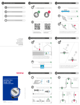
6.3 Connecion exmple
Exmple of connecion of MULTICAL® 6M2 (ype no. 6M2-G) nd flow sensor wih reed swich.
The pssive conc oupu of he flow sensor is conneced direcly o he flow sensor inpu which
is no glvniclly sepred. This permis cble lengh of mx. 10-20 m beween flow meer nd
clculor.
MULTICAL® 6M2
11
9
10
Exmple of connecion of MULTICAL® 6M2 (ype no. 6M2-G) nd flow sensor GWF UNICO2 (IPG 14)
wih reed swich. The connecion exmple cn lso be used for he flow sensor GWF MTH.
The whie nd he brown wire cn be inerchnged.
MULTICAL® 6M2
UNICO 2
Whie
Brown
MULTICAL® 6M2
11
10
5
6
7
8
9
11
9
69
51
52

13Kamstrup A/S • 55121600_B1_GB_02.2019
MULTICAL® 6M2
Exmple of connecion of MULTICAL® 6M2 (ype no. 6M2-H) nd flow sensor wih cive pulses.
The cive pulse oupu of he flow sensor is conneced o he glvniclly sepred flow sensor
inpu direcly. This permis cble lengh of up o 100 m beween flow sensor nd clculor.
MAGFLO
56
57
58
PE
10B (69B)
11B (79B)
MULTICAL® 6M2
Exmple of connecion of MULTICAL® 6M2 (ype no. 6M2-G) nd flow sensor GWF WSDH
(Reed RD 022) wih reed swich.
The blck nd he brown wire cn be inerchnged. The yellow shielding wire is no used.
MULTICAL® 6M2
WSDH
MULTICAL® 6M2
11
10
5
6
7
8
9
11
9
69
51
52
Yellow
Blck
Brown

14 Kamstrup A/S • 55121600_B1_GB_02.2019
MULTICAL® 6M2
7 Volge supply of clculor
MULTICAL® 6M2 cn be powered by buil-in lihium bery or n inegrl 24 VAC or 230 VAC
mins module.
The cble from bery or mins module is mouned in he clculor’s connecor by wo-pole
plug.
7.1 Bery supply
MULTICAL® 6M2 is conneced o lihium bery, D-cell. The bery is mrked wih insllion
yer, e.g. 2015, s well s producion de.
Opiml bery lifeime is obined by keeping he bery emperure below 30 °C.
The volge of lihium bery is lmos consn hroughou he lifeime of he bery (pprox.
3.65 V). Therefore, i is no possible o deermine he remining cpciy of he bery by
mesuring he volge.
The bery cnno nd mus no be chrged nd mus no be shor-circuied for more hn 2 sec.
Used beries mus be hnded in for pproved desrucion, e.g. Kmsrup A/S.
7.2 Mins modules
The modules re proecion clss II. They re conneced by mens of wo-wire cble (wihou
ground) hrough he cble enry of he clculor plced in he righ side of he connecing bse.
Use connecing cble wih 5-10 mm ouer dimeer nd ensure correc sripping s well s correc
mouning of cble relief.
Mx. permied fuse: 6 A.
Nionl regulions for elecric insllions mus be observed.
7.2.1 Isoled liner supply modules
Blck
Red
61
60 97
98
24 VAC supply
24 VAC
3.6 V
Blck
Red
61
60 27
28
230 VAC supply
230 VAC
3.6 V
24 VAC
For insnce 230/24 V rnsformer,
ype 66-99-403, cn be used.
Noe: MULTICAL® 6M2 cnno be
powered by 24 VDC.
230 VAC
This module is used in connecion wih direc
mins connecion.
Noe: Exernl supply mus be conneced o
he supply module.

15Kamstrup A/S • 55121600_B1_GB_02.2019
MULTICAL® 6M2
8 Tesing of funcion
Crry ou n operionl check when he energy meer hs been fully mouned. Open
hermo regulors nd vlves o esblish flow hrough he sysem. Acive he min key of
MULTICAL® 6M2 nd check h he displyed vlues for emperures nd flow re relevn vlues.
9 Informion codes ”INFO”
MULTICAL® 6M2 consnly moniors number of imporn funcions. In cse of serious error in
mesuring sysem or insllion, ”INFO” is displyed nd n info-code cn be red by civing
he min key unil he mesuring uni sys ”INFO”. The info code is only displyed when he error is
presen.
Info code Descripion Response ime
0 No irregulriies -
1 Supply volge hs been inerruped -
8 Temperure sensor T1 ouside mesuring rnge 1…10 min.
4 Temperure sensor T2 ouside mesuring rnge 1…10 min.
32 Temperure sensor T3 ouside mesuring rnge 1…10 min.
If number of info codes pper ime, he sum of info codes is displyed. If e.g. boh
emperure sensors re ouside mesuring rnge, info code 12 is displyed.

16 Kamstrup A/S • 55121600_B1_GB_02.2019
MULTICAL® 6M2
10 Plug-in modules
MULTICAL® 6M2 cn be exended by rnge of exr funcions by mens of plug-in modules. The
individul modules re briefly described below.
10.1 Module overview
MULTICAL® 6M2 Communicion op module
Type No. Descripion Module No.
602-0C 2 pulse oupus for CE nd CV 5550-1163
MULTICAL® 6M2 Communicion bse modules
Type No. Descripion Module No.
67-00-20 M-Bus + pulse inpus (VA, VB) 5550-831
67-00-24 LonWorks, FTT-10A + pulse inpus (VA, VB) 5550-1128
67-00-66 BACne MS/TP (B-ASC) RS-485 + 2 pulse inpus 5550-1240
67-00-67 Modbus RTU + 2 pulse inpus 5550-1277
10.2 Communicion op module
10.2.1 Type 602-0C: 2 pulse oupus for CE nd CV
This op module hs wo configurble pulse oupus, which
re suible for volume nd energy pulses for he meers,
cooling meers nd combined he/cooling meers.
The pulse resoluion follows he disply (deermined by he
CCC code).
E.g. CCC=119 (qp 1,5): 1 pulse/kWh nd 1 pulse/0.01 m3.
The pulse oupus re opoisoled nd wihsnd 30 VDC nd
10 mA.
Normlly energy (CE) is conneced o 16-17 nd volume (CV)
o 18-19, bu oher combinions cn be seleced by mens
of he PC progrm METERTOOL HCW, which is lso used for
selecing he pulse durion eiher 32 or 100 ms.

17Kamstrup A/S • 55121600_B1_GB_02.2019
MULTICAL® 6M2
10.3 Communicion bse modules
10.3.1 M-Bus + pulse inpus, ype 67-00-20/27/28/29
M-Bus cn be mouned in sr, ring or bus opology. Up o 250 meers cn be conneced
depending on he M-Bus Mser’s power supply nd he ol cble resisnce.
Cble resisnce < 29 Ohm
Cble cpciy < 180 nF
The M-Bus nework is conneced on erminls
24 nd 25. The polriy is unimporn.
M-Bus comes wih pulse inpus.
10.3.2 LonWorks + pulse inpus, ype 67-00-24
See installation instructions 5512-396 (DK) or 5512-403 (GB).
10.3.3 BACne® + pulse inpus, ype 67-00-66
The BACne® module communices wih BACne® on MS/TP vi RS-485 s mser/slve or
slve device.
The BACne® module rnsfers number of boh cul d s well s ccumuled d.
Furhermore, info codes for generl lrm, flow error, emperure error, wer lekge, pipe burs,
ir in sysem, nd wrong flow direcion cn be rnsmied o he BACne® Conroller.
The wo pulse inpus llow connecion nd reding of wo ddiionl meers for e.g. wer nd
elecriciy wih pulse oupu.
10.3.4 Modbus RS485 RTU* Slve Module + pulse inpus, ype 67-00-67
The Modbus bse module for MULTICAL® ensures simple inegrion of Kmsrups he,
cooling nd wer meers ino Modbus bsed sysems. Modbus is n open, widespred nd well
esblished seril communicion proocol used wihin building uomion.
Furher deils bou he Modbus module pper from d shee (DK: 5810-1267, GB: 5810-1253,
DE: 5810-1268, FR: 5810-1317).
*) RTU: Remoe Terminl Uni

18 Kamstrup A/S • 55121600_B1_GB_02.2019
MULTICAL® 6M2
11 Seup vi fron keys
De, ime nd primry M-Bus ddress cn be djused by mens of he fron keys on he
clculor’s fron.
1 In he disply you selec he reding you wn o chnge
2 Lif off he clculor op
3 Wi unil he meer hs shu down (up o 2.5 minues). Do no press ny keys
4 While remouning he clculor op, keep he min key cived for pprox. 8 seconds.
5 The seup menu is now cive.
Hving cived he seup menu he reding you wn o
chnge is displyed wih he righmos digi flshing:
(in he below exmple, he ”De” hs been seleced):
The vlue of he flshing digi cn be chnged by pressing he sub-key .
The digi is incresed by one ech ime he key is pressed, nd pssing 9 you sr from 0:
When pressing he min-key he nex digi o he righ will be flshing:
The cive digi flshes nd his digi cn now be chnged by pressing he sub-key . I is
possible o reurn o he firs digi on he righ by mens of he min key .
When he vlue of he reding hs been chnged you qui by pressing he min key
coninuously for pprox. 10 seconds.
I should be checked wheher he vlue is vlid for he reding in quesion. If so, he vlue is sved
nd n “OK” symbol is displyed. If no, he old vlue is minined, no ”OK” symbol ppers, nd
he disply revers o legl reding.

User guide
Energy Mesuremen
MULTICAL® 6M2 funcions in he following wy:
The flow sensor regisers he moun of flow circuling hrough he sysem in m3 (cubic
meres).
The emperure sensors plced in inle nd oule pipes, regiser he cooling or heing,
i.e. he difference beween inpu nd oupu emperures.
MULTICAL® 6M2 clcules consumed energy bsed on volume of he nifreeze liquid nd
emperure difference.
Redings
When he min key is cived, new reding ppers.
The sub-key displys hisoricl redings nd verge vlues.
Four minues fer he les civion of he min key he meer uomiclly swiches
o consumed energy.
Displys
Fluid ype code.
Consumed energy in kWh,
MWh or GJ. Les rge de.
Energy coun on les rge
de followed by energy coun
on ls yer’s rge de.
Followed by monhly couns.
Consumed wer. Les rge de.
Volume coun on les rge
de followed by volume coun
on ls yer’s rge de.
Followed by monhly couns.
Number of hours wih errors.
Number of opering hours.
Curren inle emperure.
Curren oule emperure.
Curren T3 emperure.
Curren wer flow.
(*) Acive o see his
yer’s mx. vlue s well s
yerly nd monhly logging
vlues.
Curren he-flow re.
(*) Acive o see his
yer’s mx. vlue s well s
yerly nd monhly logging
vlues.
Followed by ccumuled
wer consumpion
inpus A nd B nd riff
regisers TA2 nd TA3.
Curren wer flow of flow
meer conneced o V2.
De of highes regisered flow
his yer
The highes regisered flow
his yer
Followed by monhly mx. nd
min. couns.
Seril number of equipmen
conneced o inpu A.
Followed by yerly nd monhly
logging vlues.
Tolized wer consumpion
on inpu A.

Seril number of equipmen
conneced o inpu B.
Followed by yerly nd monhly
logging vlues.
Tolized wer
consumpion on
inpu B.
The firs mx. 8 digis
of he cusomer
number.
Curren informion
code.
(Conc your disric
heing compny if he
vlue differs from ”0”).
The ls 8 digis of he cusom-
er number. This exmple
displys cusomer number
12345678912.
Curren de.
Followed by cul ime.
Trge de displyed s monh
nd dy. In his exmple June 1.
The clculor’s seril number.
Followed by progrm number,
config 1 nd 2, sofwre ediion
nd sofwre checksum.
Disply es.
Followed by op nd bse module
ypes.
Reding of number of INFO code
evens.
D logger shows de …
… nd hen he INFO codes of he
les 36 evens.
Type of op module.
Followed by Top module
secondry ddress, bse module
ype nd primry nd secondry
ddresses.
(*) DDD = 401
Also see inercive user’s guides
www.kmsrup.com.
User Guide
MULTICAL® 6M2
Kamstrup A/S · Industrivej 28, Stilling · DK-8660 Skanderborg · T: +45 89 93 10 00 · inf[email protected] · kamstrup.com
Kamstrup A/S • 55121600_B1_GB_02.2019
/