Page is loading ...

1
Product Category
XTP T USW 103 • Setup Guide
The XTP T USW 103 is a three-input switcher
for sending HDMI or RGBHV video, audio,
control, and Ethernet up to 330 feet (100 m)
over a single CATx cable. This guide provides
instructions for an experienced installer to
install and connect the Extron XTP T USW 103
Universal Switcher.
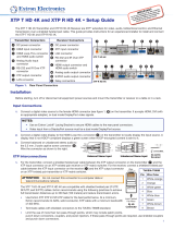
Power and Input Connections Throughput Connections Control Connections
a DC power connector and power LED
b Analog audio input connector
c Analog 15-pin HD connector
d HDMI input connectors
e XTP output connector and Sig and Link LEDs
f LAN connector and LEDs
g RS-232/IR Over XTP connector
h Contact closure connector
i RS-232 connector
j Reset button
Installation
Step 1 — Mounting
Turn off or disconnect all equipment power sources and mount the switcher as required (see the XTP T USW 103 User Guide on the Extron website,
www.extron.com, for mounting considerations).
Step 2 — Connecting Inputs
a. Connect an unbalanced analog audio input source to the 3.5 mm TRS jack (see b above). All three video inputs can share this audio input.
HDMI embedded audio is normally given priority.
b. Connect an analog RGB video source to the female 15-pin HD VGA connector, labeled input 1 (see c above).
c. Connect a digital video source to the female HDMI connectors, labeled inputs 2 and 3 (see d above). They can accept HDMI, DVI (with an
appropriate adapter), or DisplayPort video signals.
NOTES:
• Use an Extron LockIt
®
Lacing Bracket to secure HDMI cables to the connectors (see the XTP T USW 103 User Guide for insturctions).
• Video input from a DisplayPort source must be a dual mode DisplayPort source.
Step 3 — Connecting Throughput Devices
a. Connect a twisted pair cable between the XTP connector (see e above) of the XTP T USW 103 to an XTP receiver.
ATTENTION: Do not connect this connector to a computer data or telecommunications
network.
The XTP T USW 103 is compatible with CAT 5e, 6, 6a, and 7 shielded twisted pair
(F/UTP, SF/UTP, and S/FTP) and unshielded twisted pair (U/UTP) cable. Extron recommends using
the following practices to achieve full transmission distances up to 330 feet (100 m) and reduce
transmission errors.
z Use Extron XTP DTP 24 SF/UTP cable for the best performance. If not using XTP DTP 24
cable, at a minimum, Extron recommends 23 AWG, solid conductor, STP cable with a minimum
bandwidth of 400 MHz.
z Terminate cables with shielded connectors to the TIA/EIA-T568B standard.
z Limit the use of more than two pass-through points, which may include patch points, punch
down connectors, couplers, and power injectors. If these pass-through points are required, use
CAT 6 or 6a shielded couplers and punch down connectors.
NOTE: When using CAT 5e or CAT 6 cable in bundles or conduits, consider the following:
• Do not exceed 40% ll capacity in conduits.
• Do not comb the cable for the rst 20 m, where cables are straightened, aligned, and secured in tight bundles.
• Loosely place cables and limit the use of tie wraps or hook and loop fastener.
• Separate twisted pair cables from AC power cables.
Signal LED — Lights when the device is transmitting a video signal or a test pattern.
Link LED — Lights when a valid link between an XTP input and output is established.
TIA/EIA-T568B
Pin Wire Color
1 White-orange
2 Orange
3 White-green
4 Blue
5 White-blue
6 Green
7 White-brown
8 Brown
12345678
RJ-45
Connector
Insert Twisted
Pair Wires
Pins:
Pin
1
2
3
4
5
6
7
8
Wire color
White-green
Green
White-orange
Blue
White-blue
Orange
White-brown
Brown
Wire color
T568A T568B
White-orange
Orange
White-green
Blue
White-blue
Green
White-brown
Brown
POWER
12V
2
1.0 A MAX
G
1
SIG LINK
XTP OUT
LAN
AUDIO
RGB HDMI HDMI
CONTACT
Rx GGTx
RS-232 IR
RxTx
RS-232
Tx Tx
3
123
R
OVER XTP REMOTE
INPUTS
a
c
b
d
e
fg
hi
j

2
XTP T USW 103 • Setup Guide (Continued)
68-2292-50
Rev. B
09 13
AUTO
SWITCH
HDCP
SIGNAL
AUDIO
SIGNAL CLIP
XTP T USW 103
1
2
3
STATUS
© 2013 Extron Electronics — All rights reserved. All trademarks mentioned are the property of their respective owners. www.extron.com
b. To pass bidirectional serial, infrared, or other control signals, connect a control device or a device to
be controlled to the RS-232 and IR Over XTP connector (see g on page 1).
NOTE: RS-232 and IR data can be transmitted simultaneously.
c. Connect a host device or control LAN or WAN to the LAN RJ-45 connector for pass-through 10/100
Ethernet communication (see f on page 1). This is an Ethernet pass-through port with LEDs to
indicate link and activity status.
Step 4 — Connecting Control Devices
a. Connect a host device, such as a computer, to the female mini-USB B port on the front panel to congure the device or
update rmware (see the image to the right).
b. Connect a suitable contact closure device to the 3.5 mm, 4-pole captive screw connector for remote input selection
(see h on page 1). The ports labeled 1-3 select inputs 1-3 when momentarily shorted to the ground port (see the remote
contact closure image to the right).
c. For serial RS-232 control, connect a host device or control system to the 3.5 mm,
3-pole captive screw connector (see i on page 1).
Step 5 — Connecting Power
Power the XTP T USW 103 in one of the following methods:
z Connect the provided external power supply to the 2-pole captive screw connector
for local 12 V power (see a on page 1).
z Connect an XTP Power Injector to the XTP connection between the
XTP T USW 103 and a locally powered XTP receiver or XTP matrix switcher.
z Connect the XTP T USW 103 to an XTP matrix switcher and enable the remote power feature on the XTP matrix switcher.
Operation
Input Selection Buttons
The three buttons with corresponding LEDs on the front panel (labeled Mode or 1, Normal or 2,
and Auto or 3) manually select inputs 1 through 3 and enable different operating modes. The LEDs
light to indicate the active input and provide feedback.
Input selection
Press the input selection button that corresponds with the desired rear panel input connector to activate that input signal.
Auto switch mode
Press and hold (for about 3 seconds) input buttons 1 and 3 simultaneously until the Auto Switch LED lights to indicate that auto switch mode is
enabled. This prioritizes the highest numbered input receiving a video signal.
NOTE: To set auto switch mode to prioritize the lowest numbered active input, use SIS commands (see the XTP T USW 103 User Guide).
Normal switch mode
Press and hold (for about 8 seconds) inputs 1 and 2 simultaneously until the Auto Switch LED turns off to indicate that auto switch mode is disabled.
Executive mode
Press and hold (for about 5 seconds) inputs 1, 2, and 3 simultaneously until all front panel LEDs blink three times to enable or disable the front panel
lockout feature. When enabled, front panel input selection is disabled (contact closure and RS-232 control are still enabled).
Remote Configuration and Control
The XTP T USW 103 can be controlled through the Extron XTP System Conguration Software (recommended), SIS commands, remote RS-232, or
a contact closure device (see Installation for connection details).
Install the XTP System Conguration Software on a computer running a Microsoft Windows
®
operating system. The control program can be installed
from the Extron Software Products DVD or downloaded from the Extron website, www.extron.com
(see the XTP T USW 103 User Guide for more details).
Indicators
Auto Switch LED — Lights when the device is in auto switch mode.
Input selection LEDs — Light to signify status or give feedback of the currently selected
input (see Input Selection Buttons above).
Signal Status LEDs — Light when an input signal is detected on the corresponding input.
HDCP LEDs — Light when an input signal is HDCP compliant. Input 1 has no HDCP capabilities.
Audio Signal Clip LED — Lights red when the analog audio input signal remains above -3 dBFS. It remains lit for 200 ms after the signal falls below
-3 dBFS.
1 2 3
MODE NORMAL AUTO
FOX T USW 103
AUTO
SWITCH
MODE
CONFIG
NORMAL
1 2
AUTO
SIGNAL
HDCP
STATUS
3
123
Ü
CONTACT
123G
Ground
Wire Nut
Device 3
Device 2
Device 1
Remote Contact Closure
Each port senses an external switch or contact closure.
Use these ports to select an input on the switcher.
(Switches,
relays, or
similar items)
Switch
1
2
3
G
Heat
Shrink
Over
Shield
Wires
Tx/Rx
Pins
RxTx
RS-232
RxTx
TxRx
RxTx
IR Device
RS-232 Device
G
G
G
IR
/