Page is loading ...

INSTRUCTIONS MANUAL
C d. 5012o 2528 T632 G2+ ENSE REV.0122
Door Entry System
G2 Nexa Modular+
2-Wire
TEC NOLOGH Y
Audio and Video

CONTENTS
2
SET-UP WARNINGS
-Do not overtighten the screws on the power supply connector.
-Always disconnect the power supply before installing or making modifications to the devices.
-The fitting and handling of these devices must be carried out by .authorised personnel
-The wiring must run at least .40cm away from any other wiring
-Before connecting the device to the mains, check the connections between the door panel, power supply unit, distributors
monitors and audio terminals.
- ).Use the Golmar cable (2x1mmRAP-GTWIN/HF
-Always follow the instructions contained in this manual.
Introduction.....................................................................................................................................................................2
Contents..........................................................................................................................................................................2
Set-up warnings............................................................................................................................................................ 2...
Safety precautions........................................................................................................................................................ .3. .
Characteristics............................................................................................................................................................... 3..
System operation........................................................................................................................................................... 3..
Description of the Nexa Modular door panel.....................................................................................................................
........................................................................................................................................ 4.Description of the door panel
EL632 G2 module ..... .. .................................................. 5+ SE / EL642 G2+ sound ..................... ..... . ...Description of the
................................................................................................................. . 6..Description of the EL610D button modules
.....................................................................................................................................7Positioning the embedding box
..............................................................................................................................................7Preparing the cable entry
............................................................................................................................................ 8.Fitting the embedding box
..................................................................................................................................8.Mounting the electronic modules
.................................................................................................................. .9.Fastening the frame to the embedding box
................................................................................................... 9Connecting the buttons to the short connection cable .
................................................................................10Connecting the buttons to the RAP-610D short connection cable
(video installation up to 32 monitors/ apartments)............................................................10Configuring the button code
................................................................................................................... 11Configuring double button module codes ..
................................................................................................................12-13Configuring single button module codes .
(only audio installation up to 128 terminals apartments)............................................. 14-15Configuring the button code .
............................................................................................................. 1Configuring double button module codes ..6-19
................................................................................................................2 - 3Configuring single button module codes .0 2
...................................................................................................................................... 4Description of the DIP switch .2
......... 24.......................................................................Audio level jumper description (vocal synthesis and tones mode)
Description of the LED lights (low light conditions).......................................................................................................24
Description of the visual signals on the door panel.......................................................................................................25
......................................................................... 5.2Description of the vocal synthesis (audible signals on the door panel)
tion of the tones mode ............................................................................... 5Descrip ) 2.audible signals on the door panel
Description of the P1 and P2 external buttonscall ( ).. ................................ 25video module ............................................. .
Description connector to digital converter CD-NEXA/G2+ / connection illumination EL3002 module...........................26
or tones mode......................................................................................................27Selecting vocal synthesis language
.......................................... .........To change the call code P1 and P2 push button module(sound ) / final adjustments . 28..
and ............................. .......................................... ............ .29
Closing the frame nserting the button identification labelsI
.................................................... -30 32Mounting the door panel/double door panel modules and closing the door panel
Installing the lock release installation ...................................................................................................................... .......32
Installing the power supply unit (FA-G2 )... .........................................................................................+ ......................... 33..
Wiring diagrams...................................................................................................................................................... -.34 52
Installation riser types...............................................................................................................................................53-57
Con en ction of an external camera ( ..........................................58only EL632 G2+ SE sound module with colour camera).
Cleaning the door panel.................................................................................................................................................58
Not s............................................................................................................................................................................e 59
Co ...................................................................................................................................................mpliance............... .60
2
INTRODUCTION
First and foremost we would like to thank you for purchasing this product.
Our commitment to achieving the satisfaction of customers like you is manifested through our ISO-9001 certification
and the manufacture of products like the one you have just purchased.
Its advanced technology and strict quality control will ensure that customers and users enjoy the numerous features
that this device offers. To get the most out of them and ensure proper operation from day one, we recommend that you
read this instruction manual.
NEXA MODULAR G2+ AUDIO AND VIDEO DOOR ENTRY SYSTEM - BUILDING

CHARACTERISTICS
-Audio and video door entry system with simplified wiring (non-polarised 2-wire bus).
-Up to 4 access panel (DPM-G2+ multiplexer required for more than one access panel) per installation.
-Up to 3 monitors and apartments with a monitor per installation.2 ART 4 /ART 4 LITE
-Up to 3 monitors and apartments with a monitor per installation.2 ART 7 /ART 7 LITEH
-Up to 3 monitors and apartments with a monitor per installation2 ART 7W/G2+ . Only the master monitor can activate
Wi-Fi transmission (FA-ART 7W ).power supply unit required for apartment
- Up to 32 monitors/audio terminals and apartments in mixed installations (terminals and monitors).
- Up to 128 audio terminals and apartments per installation ("only audio" installation with EL642/G2+ module).
- Up to 4 monitors per apartment./audio terminals
- 8 monitors n paral el (Up to i l in 1 output (to monitor) of the distributor) ., see pages 48 and 56-57
-Up to monitors in parallel (installation without distributors) per installation.12
- G2 SEVideo module EL632 + with pan and tilt mechanism to adjust the telecamera position.
-Call confirmation tone.
-Visual signals on the door panel for people with impaired hearing (indicating call process, communication, door open
and channel busy).
-Audible signals on the door panel for people with impaired vision (indicating call in progress, ,resident unavailable
door open call finished).and
- from monitor (up to 10 seconds), see corresponding monitor user manual.Door opening timeable
-2 outputs for independently activated lock releases.
-Relay 1 output to activate the DC orAC lock releases actuated by relay.and relay 2
-Input for external door opening button (Relay output).1
-Input for external door opening button (Relay output).2
-first distribu (video door panel): 80m 1mmtor .Maximum distance between the power supply the with a cross-section of&
- :(video door panel)Maximum distance between first distributor & last distributor 80m 1mm.with a cross-section of
- Maximum distance between distributor & monitor (video door panel): 30m 1mm.with a cross-section of
- Maximum distance between power supply and door panel (video door panel): 80m 1mm.with a cross-section of
- power supply and last monitor with distributorsMaximum distance between " ": 190m 1mm.with a cross-section of
- power supply and last monitor without distributors see pagesMaximum distance between ( ): 45, 48 & 56-57.
SYSTEM OPERATION
-To make a call, the visitor must press the button of the apartment; an audible sound indicates that the call is being made and
LED will turn on. If vocal synthesis is enabled, a 'Call is in progress' message appears indicating that a call is being made.
At this moment, the apartment's monitors receive the call. If another apartment is called by mistake, press the button for the
correct apartment and the first call will be cancelled.
- Upon receiving the call, the image will appear on the screen of the master monitor (and slave 1, if it exists) without the visitor
knowing and icon displayed on the screen will blink green, the led of the ART1 terminal(s) will blink white and the led
of the T-ART terminal(s) will blink on one of the buttons of the ART 4/. To view the image from slave monitors 2 or 3, press
ART 7H monitor or of the ART 7W monitorpress the screen for the image to appear. If the call is not answered within 45
seconds, LED will turn off and the system will become free.
- To establish communication, press off-the-hook icon,press the button below off-the-hook icon of the ART 4 /ART 7H monitor
on the screen ., press the button of the ART1 terminal or lift the handset of any T-ART terminalof the ART 7W monitor
Door panel LED will .will turn off and the led turn on If the door panel has an EL3002H module with icon displayed on
the front, the LED of the EL3002H module will illuminate. Make sure that the hearing aid is 15 - 20 cm away from the door panel
to ensure maximum audio quality during communication with the apartment.
- Connection will last for 90 seconds or until on-the-hook icon isis pressed the button below of the ART 4/ ART 7 monitorH ,
pressed on-the-hook icon on the screen , is pressed the button of the ART1 terminal or the handsetof theART 7W monitor
is hung up in the T-ART terminal door panel. When communication ends, LED will turn off and the system will become free. If
vocal synthesis is enabled, a 'Communication is finished' message will indicate that the call is over.
- , press theTo open door of the door panel H ,or press the corresponding button below of the ART 4 /ART 7 monitor
corresponding icon on the screen or press the corresponding button door 1 or door 2 of anyof the ART 7W monitor
terminal of the apartment, 3during the call or communication processes: one press will activate the lock release for seconds and
LED will also turn on for seconds. If vocal synthesis is enabled, a 'Door open' message will be indicated on the door panel.3 is
- and configuration , see user manualDetailed operation of the monitor/terminal the corresponding monitor .
3
2
2
SAFETY PRECAUTIONS
-Always disconnect the power supply before installing or making modifications to the devices.
-..The fitting and handling of these devices must be carried out by authorised personnel
-The wiring must run at least 40 cm away from any other wiring.
-On the power supply unit:
wDo not overtighten the screws on the connector.
wInstall the power supply unit in a dry and protected place free from the risk of water leaks or sprays.
wAvoid locations that are humid, dusty or near heat sources.
wEnsure that the air vents are free from obstruction so that air can circulate freely.
wTo avoid damage, the power supply unit must be firmly secured in place.
wTo prevent electric shock, do not remove the cover or handle the wiring connected to the terminals.
2
2
12
2
NEXA MODULAR G2+ AUDIO AND VIDEO DOOR ENTRY SYSTEM - BUILDING

4
Video module
2/G2 SEEL63 +
EL642/G2+
,in video door entry systems with colour television camera.
in audio door entry systems.
,
DESCRIPTION OF THE NEXA MODULAR DOOR PANEL
Button module
EL610D
Short connection cable supplied with the EL610A module (length 16 cm).
,for 5 individual or 10 double buttons.
RAP-610D connection cable (length 27 cm).
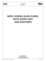
Door panel component assembly drawing.
Aluminium panel
Electronic
modules
Frame modulesEmbedding boxes
Description of the door panel.
For connecting the buttons between the sound module and the EL610D button module and
between EL610D button modules.
For connecting the buttons between the sound module and the EL610D button module and
between EL610D button modules.
This hose is required when the distance between modules to be connected is greater due to
their distribution in the door panels.
Description of the door panel:
Grille modules:
N1000/AL
N1110/AL 1P.
N2220/AL 2P.
Clip-on covers: 60xx
Button module: 3xxx
Nexa module separator
Fixing screws for clip-on covers (x4)
Side profile (x2)
Side profile Door panel UNE rod
*
Fixing screws for embedding box (x2)
*
Door panel UNE rod: Enables 2 door panels to be joined (see page ).31
NEXA MODULAR G2+ AUDIO AND VIDEO DOOR ENTRY SYSTEM - BUILDING

DESCRIPTION OF THE EL632 G2 P/T MODULE+ SOUND + ES / EL642 G2+EL632 G2
5
Nota: (pages to )34 52 .See wiring diagrams for connections
Description of the + ES / EL642 G2+ sound moduleEL632 G2 :
Microphone.
Speaker.
Front.
Video module push buttons P1 & P2 (x2).
Connector (Bus G2 ).+
External call push buttons P1 & P2 connector.
Back side.
: Positive, negative (12Vdc output for Golmar DC electric lock).
: Contact “C”for electric lock (Relay 1).
: Contact “NO”for electric lock (Relay 1).
: Input for external door opening button (Relay 1).
: s s and Relay 2Input for external door opening button (Relay 1 ).
: 2Input for external door opening button (Relay ).
: Contact "C" (Rel 2).for electric lock ay
: Contac “N.O”for electric lock (Relay 2).
: Contac "N.C" (Rel 2)for electric lock ay
: Input for CCTV analogic camera .GND (only EL632 G2+ SE sound module)
: Input for CCTV analogic camera (only EL632 G2+ SE sound module).
: Connection BUS (non-polarised).
: Connection BUS (non-polarised).
"P1" y "P2" of the modulesound .
button number
Colour telecamera (only EL632 G2+ SE sound module).
+,
C1
NA1
AP+
AP
AP+
C2
NA2
NC2
GND
CCTV
BUS
BUS
_
Connection terminals:
No utilizar (uso interno).
EL3002H module connector.
LEDs (visual signals for people with impaired hearing).
LEDs (activation in low light conditions).
(Only EL632 G2+ SE sound module).
Connector to CD-NEXA/G2+ digital converter module.
_
Jumper for volume control of the “tones mode”and “vocal
(m , m )inimum aximum and mute of the door panel.synthesis”
Configuration DIP switch.
Door panel audio adjustment.
Monitor audio adjustment.
EL610D button module connector
NEXA MODULAR G2+ AUDIO AND VIDEO DOOR ENTRY SYSTEM - BUILDING
Connector to CD-NEXA/G2+ digital converter module.
1 2 3 4 5 6 7 8 9 10

6
DESCRIPTION OF THE EL610D BUTTON MODULE
Front.
Module buttons (x10).
DIP switch (button call code).
Button number.
Button connector input/output (x3).
Back.
Description of the EL610D button module:
NEXA MODULAR G2+ AUDIO AND VIDEO DOOR ENTRY SYSTEM - BUILDING

7
INSTALLATION OF THE DOOR PANEL
1
N V SCE 90C
99
132,5
56,5
M dul so e
Model
W (width)
H (height)
D (depth)
2
CEV90CN
99
238
56
3
CEV90
99 mm.
328 mm.
56 mm.
Break through the hole to allow entry of cables through the bottom part of
the embedding box.
In the case of door panels with more than one embedding box, break through
the side holes and join the embedding boxes using cable grommets.
1650
1850
1450
Make a hole in the wall to position the top of the door panel at a height of 1.65m.
Hole dimensions depend on the type of door panel.
The door panel has been designed to be used under most environmental conditions. It is however advisable to
take extra precautions to prolong its service life (shields, covered areas, etc.). To obtain optimum video door
entry system image quality, avoid direct contact from light sources (sunshine, street lights, etc.)
Positioning the embedding box:
Preparing the cable entry:
NEXA MODULAR G2+ AUDIO AND VIDEO DOOR ENTRY SYSTEM - BUILDING

8
EL632/G2+ SE
EL642/G2+
modulesound
Pass the cable through the hole made in the
embedding box. Embed the box and ensure
that it is level and flush. Once the embedding
box is positioned, remove the protective stickers
from the door panel's fixing holes.
Insert the sound module into the top of the frame module.
Line up the clips on the sound module with the respective housings on the frame module and then
press gently until correctly positioned.
EL610D
button module
Frame
If there is a button module, repeat the above process, positioning it below the sound module, as shown
in the drawing.
Frame
INSTALLATION OF THE DOOR PANEL
Fitting the embedding box:
Mounting the electronic modules:
NEXA MODULAR G2+ AUDIO AND VIDEO DOOR ENTRY SYSTEM - BUILDING

9
1 2 3 4 5 6 7 8 9 10
INSTALLATION OF THE DOOR PANEL
Fastening the frame to the embedding box:
Insert the spring hinge which attaches to the product in the embedding
box, as shown in the drawing.
To fasten the frame to the embedding box, insert the spring
hinge into the housings provided for this purpose in the
frame, as shown in the drawing.
The frame can now be tilted horizontally to enable
sound module and button module connection
and setting.
Between EL610D button modules in the same embedding box, insert the short
connection cable from the lower connector of the first button module into the
upper connector of the second button module, as shown in the drawing.
Insert one end of the short connection cable supplied with the EL610D
product into the sound module connector and the other end into the
connector situated at the top of the EL610D button module, as shown in the
drawing.
Between EL610D button modules in different embedding boxes, insert one
end of the short connection cable into the lower connector of the final
EL610D module in the first embedding box and the other end into the
middle connector of the last EL610D button module situated at the bottom
of the second embedding box, as shown in the drawing.
Connecting the buttons to the short connection cable:
NEXA MODULAR G2+ AUDIO AND VIDEO DOOR ENTRY SYSTEM - BUILDING

10
Important: Select a different configuration option for each EL610D module.
Note: V04 & later, c d "128" n P1 "127" n P2.EL632 G2+ SE module factory default with the o e i and i
EL632 G2+ SE V03, c d "32" n P1 "31" n P2.module factory default with the o e i and i
Note: 3 SE module V04 & later P1 and P2 push buttons must be changed the call codeEL6 2 G2+ ,
.(for example "32" in P1 and "31" in P2), see page 28
*
( ) Factory .default
2
Dip1
1
3
Dip2
Dip3
Dip4
Dip5
Dip6
Dip7
Dip8
P1
1
21
11
On
Off
Off
Off
Off
On
Off
On
Off
Off
Off
Off
Off
Off
Off
Off
Off
Off
Off
Off
Off
On
On
On
P2 P3 P4 P5 P6 P7
2
22
12
3
23
13
4
24
14
5
25
15
6
26
16
7
27
17
8
28
18
9
29
19
10
30
20
P8 P9 P10 (1)
*
( )
2
Dip1
1
4
6
3
5
7
Dip2
Dip3
Dip4
Dip5
Dip6
Dip7
Dip8
P1
1
11
21
31
6
16
26
On
Off
Off
Off
Off
Off
Off
Off
Off
Off
Off
On
Off
Off
Off
On
Off
Off
Off
Off
Off
Off
Off
Off
Off
Off
On
Off
Off
Off
On
Off
Off
Off
Off
Off
Off
Off
Off
Off
Off
On
Off
Off
Off
On
Off
Off
Off
On
On
On
On
On
On
On
P3 P5 P7 P9
2
12
22
_
7
17
27
3
13
23
8
18
28
4
14
24
9
19
29
5
15
25
10
20
30
(1)
*
( )
_ _ _
P1- P10: Button 1 - button 10
(1)
INSTALLATION OF THE DOOR PANEL
Connecting the buttons to the RAP-610D short connection cable:
Use the RAP-610D connection cable to connect the buttons between the sound
module and the EL610D button module and between EL610D button modules when
the distance between modules to be connected is greater due to the composition of
the door panels.
*
( )
Configuring the button code (video installation up to 32 monitors/ apartments:
The EL610D button module needs to be configured in order to assign
a call code to the buttons. Carry out this configuration with the
DIP switch located at the back of the module.
Depending on the configuration option selected, the buttons will be
assigned with a certain call code.
To configure the call code on the monitors. It is worth noting the call
code of each button, as shown in the table below.
IMPORTANT: Mixed installation with monitors and audio terminals up to 32 elements/apartments.
NOTE: Installations of up to 128 monitors with module EL632 G2+ SE V04 & later, (see manual "TRD-G2+"
Code 50122552). EL610D button module
Module configuration option
DIP switch Button code
Double button module codes
Single button module codes
NEXA MODULAR G2+ AUDIO AND VIDEO DOOR ENTRY SYSTEM - BUILDING

11
EL632 G2+ SE
Monitor Code Monitor CodeMonitor Code
Code 13 Code 32
C d. 10o C d. 9o
C d. 8o C d. 7o
C d. 6o C d. 5o
C d. 4o C d. 3o
C d. 2o C d. 1o
C d. 20o C d. 19o
C d. 18o C d. 17o
C d. 16o C d. 15o
C d. 14o C d. 13o
C d. 12o C d. 1o 1
C d. 30o C d. 29o
C d. 28o C d. 27o
C d. 26o C d. 25o
C d. 24o C d. 23o
C d. 22o C d. 1o 2
C d. 1o 3 C d.o 32
INSTALLATION OF THE DOOR PANEL
Configuring double button module codes:
Front Back
NEXA MODULAR G2+ AUDIO AND VIDEO DOOR ENTRY SYSTEM - BUILDING
( )
*
P1P2 P2
1 2 3 4 5 6 7 8
ON
9 10
78
56
34
12
1 2 3 4 5 6 7 8
ON
9 10
78
56
34
12
1 2 3 4 5 6 7 8
ON
9 10
78
56
34
12
EL610D
12
ON
2 3 4 5 6 7 8 9 10
NA2
+AP-
C1 NA1 AP+ C2
AP+
GND
BUSBUS
Relé 2Relé 1
_
12Vdc
NC2
CCTV
1 2 3
ON DIP
4 5
ON DIP
1 2 3
ON DIP
4 5
ON DIP
1 2 3
ON DIP
4 5
ON DIP
ART 7W/G2+
ART 7H/G2+
ART 4/G2+
ART 7W/G2+
ART 7H/G2+
ART 4/G2+
( )
*
Note: 3 SE module V04 & later P1 and P2 push buttons must be changed the factory default call codeEL6 2 G2+ ,
.(for example "32" in P1 and "31" in P2), see page 28
8
8676 7
( )
*
8
8676 7
Code 13
1 2 3
ON DIP
4 5
ON DIP
1 2 3
ON DIP
4 5
ON DIP
8
8676 7
( )
*
Code 10 Code 9
Code 8 Code 7
Code 6 Code 5
Code 4 Code 3
Code 2 Code 1
Code 20 Code 19
Code 18 Code 17
Code 16 Code 15
Code 14 Code 13
Code 12 Code 11
Code 30 Code 29
Code 28 Code 27
Code 26 Code 25
Code 24 Code 23
Code 22 Code 12
1 2 3
ON DIP
4 5
ON DIP
123
ON DIP
45
ON DIP
1 2 3
ON DIP
45
ON DIP
12 3
ON DIP
4 5
ON DIP
123
ON DIP
4 5
ON DIP
1 2 3
ON DIP
45
ON DIP
123
ON DIP
45
ON DIP
1 2 3
ON DIP
45
ON DIP
12 3
ON DIP
45
ON DIP
1 2 3
ON DIP
45
ON DIP
1 2 3
ON DIP
4 5
ON DIP
1 2 3
ON DIP
4 5
ON DIP
12 3
ON DIP
45
ON DIP
123
ON DIP
4 5
ON DIP
1 2 3
ON DIP
4 5
ON DIP
12 3
ON DIP
45
ON DIP
1 2 3
ON DIP
4 5
ON DIP
123
ON DIP
4 5
ON DIP
1 2 3
ON DIP
4 5
ON DIP
12 3
ON DIP
4 5
ON DIP
1 2 3
ON DIP
45
ON DIP
12 3
ON DIP
45
ON DIP
1 2 3
ON DIP
45
ON DIP
123
ON DIP
45
ON DIP
1 2 3
ON DIP
45
ON DIP
123
ON DIP
4 5
ON DIP
1 2 3
ON DIP
45
ON DIP
123
ON DIP
45
ON DIP
12 3
ON DIP
4 5
ON DIP
88676 7
8
8676 7
8
8676 7
8
8676 7
8
8676 7
8
8676 7
8
8676 7
8
8676 7
8
8676 7
8
8676 7
8
8676 7
8
8676 7
8
8676 7
8
8676 7
88676 7
88676 7
88676 7
88676 7
88676 7
88676 7
88676 7
88676 7
88676 7
88676 7
88676 7
88676 7
88676 7
88676 7
88676 7
88676 7
Code 10
Code 8
Code 6
Code 4
Code 2
Code 20
Code 18
Code 16
Code 14
Code 12
Code 30
Code 28
Code 26
Code 24
Code 22
1 2 3
ON DIP
4 5
ON DIP
123
ON DIP
45
ON DIP
1 2 3
ON DIP
45
ON DIP
12 3
ON DIP
4 5
ON DIP
123
ON DIP
4 5
ON DIP
1 2 3
ON DIP
45
ON DIP
123
ON DIP
45
ON DIP
1 2 3
ON DIP
45
ON DIP
12 3
ON DIP
45
ON DIP
1 2 3
ON DIP
45
ON DIP
1 2 3
ON DIP
4 5
ON DIP
1 2 3
ON DIP
4 5
ON DIP
12 3
ON DIP
45
ON DIP
123
ON DIP
4 5
ON DIP
88676 7
8
8676 7
8
8676 7
8
8676 7
8
8676 7
8
8676 7
8
8676 7
8
8676 7
8
8676 7
8
8676 7
8
8676 7
8
8676 7
8
8676 7
8
8676 7
1 2 3
ON DIP
4 5
ON DIP
8
8676 7 1 2 3
ON DIP
4 5
ON DIP
8
8676 7

12
1 2 3 4 5 6 7 8
ON
9 10
78
56
34
12
1 2 3 4 5 6 7 8
ON
9 10
78
56
34
12
1 2 3 4 5 6 7 8
ON
9 10
78
56
34
12
P1
P2 P2
EL610D
Code 32
Code 5
Code 4
Code 3
Code 2
Code 1
Code 10
Code 9
Code 8
Code 7
Code 6
Code 15
Code 14
Code 13
Code 12
Code 11
Monitor Code
P1
Code 5
Code 4
Code 3
Code 2
Code 1
Code 9
Code 8
Code 7
Code 6
Code 11
Code 32
Code 10
Code 15
Code 14
Code 13
Code 12
12
ON
2 3 4 5 6 7 8 9 10
NA2
+AP-
C1 NA1 AP+ C2
AP+
GND
BUSBUS
Relé 2Relé 1
_
12Vdc
NC2
CCTV
ART 7W/G2+
ART 7H/G2+
ART 4/G2+
INSTALLATION OF THE DOOR PANEL
Configuring single button module codes:
Not used
Not used
Not used
Not used
Not used
Not used
Not used
Not used
Not used
Not used
Not used
Not used
Not used
Not used
Not used
Not used
Front Back
Not used
Not used
Not used
Not used
Not used
Not used
Not used
Not used
Not used
Not used
Not used
Not used
Not used
Not used
Not used
Continued overleaf
NEXA MODULAR G2+ AUDIO AND VIDEO DOOR ENTRY SYSTEM - BUILDING
( )
*
EL632 G2+ SE
( )
*Note: 3 SE module V04 & later P1 push button must be changed the factory default call code “128"EL6 2 G2+ ,
.(for example "32" in P1), see page 28
123
ON DIP
4 5
ON DIP
1 2 3
ON DIP
4 5
ON DIP
1 2 3
ON DIP
4 5
ON DIP
123
ON DIP
4 5
ON DIP
12 3
ON DIP
4 5
ON DIP
123
ON DIP
45
ON DIP
12 3
ON DIP
45
ON DIP
1 2 3
ON DIP
45
ON DIP
1 2 3
ON DIP
4 5
ON DIP
12 3
ON DIP
4 5
ON DIP
12 3
ON DIP
45
ON DIP
1 2 3
ON DIP
45
ON DIP
1 2 3
ON DIP
45
ON DIP
1 2 3
ON DIP
45
ON DIP
123
ON DIP
45
ON DIP
1 2 3
ON DIP
4 5
ON DIP
6 7 8
88676 7
88676 7
88676 7
88676 7
88676 7
88676 7
88676 7
88676 7
88676 7
88676 7
88676 7
88676 7
88676 7
88676 7
88676 7
Not used

13
1 2 3 4 5 6 7 8
ON
9 10
78
56
34
12
1 2 3 4 5 6 7 8
ON
9 10
78
56
34
12
1 2 3 4 5 6 7 8
ON
9 10
78
56
34
12
1 2 3 4 5 6 7 8
ON
9 10
78
56
34
12
EL610D
Monitor Code
Code 20
Code 19
Code 18
Code 17
Code 16
Code 25
Code 24
Code 23
Code 22
Code 21
Code 30
Code 29
Code 28
Code 27
Code 26
Code 31
INSTALLATION OF THE DOOR PANEL
Continued from previous page.
Not used
Not used
Not used
Not used
Not used
Not used
Not used
Not used
Not used
Not used
Not used
Not used
Not used
Not used
Not used
Not used
Not used
Not used
Not used
Not used
Not used
Not used
Not used
Not used
Not used
Not used
Not used
Not used
Not used
Not used
Not used
Not used
Not used
Not used
Not used
Not used
Not used
Not used
Not used
Not used
Not used
Not used
Not used
Not used
Code 25
Code 24
Code 23
Code 22
Code 21
Code 30
Code 29
Code 28
Code 27
Code 26
C 31ode
C 20ode
Code 19
Code 18
Code 17
C 16ode
NEXA MODULAR G2+ AUDIO AND VIDEO DOOR ENTRY SYSTEM - BUILDING
12 3
ON DIP
4 5
ON DIP
1 2 3
ON
4 5
ON
1 2 3
ON DIP
45
ON DIP
12 3
ON DIP
45
ON DIP
123
ON DIP
45
ON DIP
12 3
ON DIP
4 5
ON DIP
123
ON DIP
4 5
ON DIP
1 2 3
ON DIP
4 5
ON DIP
1 2 3
ON DIP
4 5
ON DIP
123
ON DIP
4 5
ON DIP
1 2 3
ON DIP
4 5
ON DIP
1 2 3
ON DIP
45
ON DIP
1 2 3
ON DIP
45
ON DIP
123
ON DIP
45
ON DIP
12 3
ON DIP
45
ON DIP
1 2 3
ON DIP
45
ON DIP
88676 7
88676 7
88676 7
88676 7
88676 7
88676 7
88676 7
88676 7
88676 7
88676 7
88676 7
88676 7
88676 7
88676 7
88676 7
88676 7

The EL610D button module needs to be configured in order to assign
a call code to the buttons. Carry out this configuration with the
DIP switch located at the back of the module.
Depending on the configuration option selected, the buttons will be
assigned with a certain call code.
To configure the call code on the monitors. It is worth noting the call
code of each button, as shown in the table below.
IMPORTANT: Only audio installation up to 128 terminals/apartments with EL642 G2+ sound module.
*
( )
Configuring the button code (audio only installation up to 128 te /apartmentsrminals with EL642 G2+
sound module):
EL610D button module
2
Dip1
1
3
Dip2
Dip3
Dip4
Dip5
Dip6
Dip7
Dip8
Module configuration option
P1
1
21
11
DIP switch
On
Off
Off
Off
Off
On
Off
On
Off
Off
Off
Off
Off
Off
Off
Off
Off
Off
Off
Off
Off
On
On
On
Button code
P2 P3 P4 P5 P6 P7
2
22
12
3
23
13
4
24
14
5
25
15
6
26
16
7
27
17
8
28
18
9
29
19
10
30
20
P8 P9 P10 (1)
*
( )
Double button module codes
4 31Off Off Off On Off Off Off On 32 33 34 35 36 37 38 39 40
5 41Off Off Off Off On Off Off On 42 43 44 45 46 47 48 49 50
6 51Off Off Off Off Off On Off On 52 53 54 55 56 57 58 59 60
7 61Off Off Off Off Off Off On On 62 63 64 65 66 67 68 69 70
8 71On Off Off Off Off Off Off Off 72 73 74 75 76 77 78 79 80
9 81Off On Off Off Off Off Off Off 82 83 84 85 86 87 88 89 90
10 91Off Off On Off Off Off Off Off 92 93 94 95 96 97 98 99 100
11 1 10Off Off Off On Off Off Off Off 102103104105106107108109110
12 1 11Off Off Off Off On Off Off Off 112113114115116117118119120
13 Off Off Off Off Off On Off Off 122123124125126127 _ _
Important: Select a different configuration option for each EL610D module.
Note: EL642 G2+ module V02 & later, c d "128" n P1 "128" n P2.factory default with the o e i and i
Note: EL642 G2+ module V01, c d "32" n P1 "31" n P2.factory default with the o e i and i
Note: module V01 P1 and P2 push buttons must be changed the factory default call codeEL642 G2+ ,
.(for example "128" in P1 and "127" in P2), see page 28
*
( ) Factory default.
P1- P10: Button 1 - button 10
(1)
1 12 1 82
14
INSTALLATION OF THE DOOR PANEL
NEXA MODULAR G2+ AUDIO AND VIDEO DOOR ENTRY SYSTEM - BUILDING
Continued overleaf

15
INSTALLATION OF THE DOOR PANEL
NEXA MODULAR G2+ AUDIO AND VIDEO DOOR ENTRY SYSTEM - BUILDING
EL610D button module
Module configuration option
DIP switch Button code
2
Dip1
1
4
6
3
5
7
Dip2
Dip3
Dip4
Dip5
Dip6
Dip7
Dip8
P1
1
11
21
31
6
16
26
On
Off
Off
Off
Off
Off
Off
Off
Off
Off
Off
On
Off
Off
Off
On
Off
Off
Off
Off
Off
Off
Off
Off
Off
Off
On
Off
Off
Off
On
Off
Off
Off
Off
Off
Off
Off
Off
Off
Off
On
Off
Off
Off
On
Off
Off
Off
On
On
On
On
On
On
On
P3 P5 P7 P9
2
12
22
7
17
27
3
13
23
8
18
28
4
14
24
9
19
29
5
15
25
10
20
30
(1)
*
( )
Single button module codes
9
8
11
13
10
12
14
36
46
56
66
41
51
61
On
Off
Off
Off
Off
Off
Off
Off
Off
Off
Off
On
Off
Off
Off
On
Off
Off
Off
Off
Off
Off
Off
Off
Off
Off
On
Off
Off
Off
On
Off
Off
Off
Off
Off
Off
Off
Off
Off
Off
On
Off
Off
Off
On
Off
Off
Off
Off
Off
Off
Off
Off
Off
Off
37
47
57
42
52
62
38
48
58
43
53
63
39
49
59
44
54
64
40
50
60
45
55
65
32 33 34 35
67 68 69 70
Important: Select a different configuration option for each EL610D module.
Note: EL642 G2+ module V02 & later, factory default with the code "128" in P1.
EL642 G2+ module V01, factory default with the code "32" in P1.
Note: module P1 push button must be changed the call code for exampleEL642 G2+ ,
in P1 see page 28“71" , ( ).
*
( ) Factory default.
P1- P10: Button 1 - button 10
(1)
Continued from previous page.

16
INSTALLATION OF THE DOOR PANEL
NEXA MODULAR G2+ AUDIO AND VIDEO DOOR ENTRY SYSTEM - BUILDING
Configuring double button module codes ( 128 terminals/ ):up to apartments
P1P2 P2
1 2 3 4 5 6 7 8
ON
9 10
78
56
34
12
1 2 3 4 5 6 7 8
ON
9 10
78
56
34
12
1 2 3 4 5 6 7 8
ON
9 10
78
56
34
12
P1
EL610D
Terminal code T rminal codee
Code 127 Code 128
Code 9
Code 7
Code 5
Code 3
Code 1
Code 19
Code 17
Code 15
Code 13
Code 29
Code 27
Code 25
Code 23
Code 12
T rminal codee
Code 127
( )
**
Code 10 Code 9
Code 8 Code 7
Code 6 Code 5
Code 4 Code 3
Code 2 Code 1
Code 20 Code 19
Code 18 Code 17
Code 16 Code 15
Code 14 Code 13
Code 12 Code 11
Code 30 Code 29
Code 28 Code 27
Code 26 Code 25
Code 24 Code 23
Code 22 Code 21
Front Back
Code 1 82
12
ON
2 3 4 5 6 7 8 9 10
NA2
+AP-
C1 NA1 AP+ C2
AP+
GND
BUSBUS
Relé 2Relé 1
_
12Vdc
NC2
CCTV
EL6 2 G24 +
Code 10
Code 8
Code 6
Code 4
Code 2
Code 20
Code 18
Code 16
Code 14
Code 12
Code 30
Code 28
Code 26
Code 24
Code 22
123
ON DIP
4 5 6 7 8
ON DIP
123
ON DIP
4 5 6 7 8
ON DIP
123
ON DIP
4 5 6 7 8
ON DIP
123
ON DIP
4 5 6 7 8
ON DIP
123
ON DIP
4 5 6 7 8
ON DIP
123
ON DIP
4 5 6 7 8
ON DIP
123
ON DIP
4 5 6 7 8
ON DIP
123
ON DIP
4 5 6 7 8
ON DIP
123
ON DIP
4 5 6 7 8
ON DIP
123
ON DIP
4 5 6 7 8
ON DIP
123
ON DIP
4 5 6 7 8
ON DIP
123
ON DIP
4 5 6 7 8
ON DIP
123
ON DIP
4 5 6 7 8
ON DIP
123
ON DIP
4 5 6 7 8
ON DIP
123
ON DIP
4 5 6 7 8
ON DIP
123
ON DIP
4 5 6 7 8
ON DIP
Code 11
123
ON DIP
4 5 6 7 8
ON DIP
123
ON DIP
4 5 6 7 8
ON DIP
123
ON DIP
4 5 6 7 8
ON DIP
123
ON DIP
4 5 6 7 8
ON DIP
123
ON DIP
4 5 6 7 8
ON DIP
123
ON DIP
4 5 6 7 8
ON DIP
123
ON DIP
4 5 6 7 8
ON DIP
123
ON DIP
4 5 6 7 8
ON DIP
123
ON DIP
4 5 6 7 8
ON DIP
123
ON DIP
4 5 6 7 8
ON DIP
123
ON DIP
4 5 6 7 8
ON DIP
123
ON DIP
4 5 6 7 8
ON DIP
123
ON DIP
4 5 6 7 8
ON DIP
123
ON DIP
4 5 6 7 8
ON DIP
123
ON DIP
4 5 6 7 8
ON DIP
123
ON DIP
4 5 6 7 8
ON DIP
Code 1 72
( )
**
Note: EL642 G2+ module V02 & later, c d "128" n P1 "128" n P2.factory default with the o e i and i
( )
*
T-ART/G2+
ART 1/G2+
AUX
T-ART/G2+
ART 1/G2+
AUX

17
INSTALLATION OF THE DOOR PANEL
NEXA MODULAR G2+ AUDIO AND VIDEO DOOR ENTRY SYSTEM - BUILDING
1 2 3 4 5 6 7 8
ON
9 10
78
56
34
12
1 2 3 4 5 6 7 8
ON
9 10
78
56
34
12
1 2 3 4 5 6 7 8
ON
9 10
78
56
34
12
1 2 3 4 5 6 7 8
ON
9 10
78
56
34
12
T rminal codee T rminal codeeT rminal codee
Code 40
Code 38
Code 36
Code 34
Code 32
Code 50
Code 48
Code 46
Code 44
Code 42
Code 60
Code 58
Code 56
Code 54
Code 52
Code 70
Code 68
Code 66
Code 64
Code 62
Code 49
Code 47
Code 45
Code 43
Code 14
Code 59
Code 57
Code 55
Code 53
Code 15
Code 69
Code 67
Code 65
Code 63
Code 16
Code 39
Code 37
Code 35
Code 33
Code 13
EL610D
Code 50 Code 49
Code 48 Code 47
Code 46 Code 45
Code 44 Code 43
Code 42 C 1ode 4
C 0ode 4 Code 39
Code 38 Code 37
Code 36 Code 35
Code 34 Code 33
Code 32 C 1ode 3
Code 60 Code 59
Code 58 Code 57
Code 56 Code 55
Code 54 Code 53
Code 52 C 1ode 5
Code 70 Code 69
Code 68 C 67ode
Code 66 Code 65
Code 64 Code 63
Code 62 C 1ode 6
123
ON DIP
4 5 6 7 8
ON DIP
123
ON DIP
4 5 6 7 8
ON DIP
123
ON DIP
4 5 6 7 8
ON DIP
123
ON DIP
4 5 6 7 8
ON DIP
123
ON DIP
4 5 6 7 8
ON DIP
123
ON DIP
4 5 6 7 8
ON DIP
123
ON DIP
4 5 6 7 8
ON DIP
123
ON DIP
4 5 6 7 8
ON DIP
123
ON DIP
4 5 6 7 8
ON DIP
123
ON DIP
4 5 6 7 8
ON DIP
123
ON DIP
4 5 6 7 8
ON DIP
123
ON DIP
4 5 6 7 8
ON DIP
123
ON DIP
4 5 6 7 8
ON DIP
123
ON DIP
4 5 6 7 8
ON DIP
123
ON DIP
4 5 6 7 8
ON DIP
123
ON DIP
4 5 6 7 8
ON DIP
123
ON DIP
4 5 6 7 8
ON DIP
123
ON DIP
4 5 6 7 8
ON DIP
123
ON DIP
4 5 6 7 8
ON DIP
123
ON DIP
4 5 6 7 8
ON DIP
123
ON DIP
4 5 6 7 8
ON DIP
123
ON DIP
4 5 6 7 8
ON DIP
123
ON DIP
4 5 6 7 8
ON DIP
123
ON DIP
4 5 6 7 8
ON DIP
123
ON DIP
4 5 6 7 8
ON DIP
123
ON DIP
4 5 6 7 8
ON DIP
123
ON DIP
4 5 6 7 8
ON DIP
123
ON DIP
4 5 6 7 8
ON DIP
123
ON DIP
4 5 6 7 8
ON DIP
123
ON DIP
4 5 6 7 8
ON DIP
123
ON DIP
4 5 6 7 8
ON DIP
123
ON DIP
4 5 6 7 8
ON DIP
123
ON DIP
4 5 6 7 8
ON DIP
123
ON DIP
4 5 6 7 8
ON DIP
123
ON DIP
4 5 6 7 8
ON DIP
123
ON DIP
4 5 6 7 8
ON DIP
123
ON DIP
4 5 6 7 8
ON DIP
123
ON DIP
4 5 6 7 8
ON DIP
123
ON DIP
4 5 6 7 8
ON DIP
123
ON DIP
4 5 6 7 8
ON DIP
Code 40
Code 38
Code 36
Code 34
Code 32
Code 50
Code 48
Code 46
Code 44
Code 42
Code 60
Code 58
Code 56
Code 54
Code 52
Code 70
Code 68
Code 66
Code 64
Code 62
123
ON DIP
4 5 6 7 8
ON DIP
123
ON DIP
4 5 6 7 8
ON DIP
123
ON DIP
4 5 6 7 8
ON DIP
123
ON DIP
4 5 6 7 8
ON DIP
123
ON DIP
4 5 6 7 8
ON DIP
123
ON DIP
4 5 6 7 8
ON DIP
123
ON DIP
4 5 6 7 8
ON DIP
123
ON DIP
4 5 6 7 8
ON DIP
123
ON DIP
4 5 6 7 8
ON DIP
123
ON DIP
4 5 6 7 8
ON DIP
123
ON DIP
4 5 6 7 8
ON DIP
123
ON DIP
4 5 6 7 8
ON DIP
123
ON DIP
4 5 6 7 8
ON DIP
123
ON DIP
4 5 6 7 8
ON DIP
123
ON DIP
4 5 6 7 8
ON DIP
123
ON DIP
4 5 6 7 8
ON DIP
123
ON DIP
4 5 6 7 8
ON DIP
123
ON DIP
4 5 6 7 8
ON DIP
123
ON DIP
4 5 6 7 8
ON DIP
123
ON DIP
4 5 6 7 8
ON DIP
Continued from previous page.
Continued overleaf

18
INSTALLATION OF THE DOOR PANEL
NEXA MODULAR G2+ AUDIO AND VIDEO DOOR ENTRY SYSTEM - BUILDING
1 2 3 4 5 6 7 8
ON
9 10
78
56
34
12
1 2 3 4 5 6 7 8
ON
9 10
78
56
34
12
1 2 3 4 5 6 7 8
ON
9 10
78
56
34
12
1 2 3 4 5 6 7 8
ON
9 10
78
56
34
12
EL610D
Code 80
Code 78
Code 76
Code 74
Code 72
Code 90
Code 88
Code 86
Code 84
Code 82
Code 100
Code 98
Code 96
Code 94
Code 92
Code 110
Code 108
Code 106
Code 104
Code 102
Code 89
Code 87
Code 85
Code 83
Code 18
Code 99
Code 97
Code 95
Code 93
Code 19
Code 109
Code 107
Code 105
Code 103
Code 1 10
Code79
Code 77
Code 75
Code 73
Code 17
123
ON
4 5 6 7
123
ON
4 5 6 7
123
ON
4 5 6 7
123
ON
4 5 6 7
123
ON
4 5 6 7
123
ON
4 5 6 7
123
ON
4 5 6 7
123
ON
4 5 6 7
123
ON
4 5 6 7
123
ON
4 5 6 7
123
ON
4 5 6 7
123
ON
4 5 6 7
123
ON
4 5 6 7
123
ON
4 5 6 7
123
ON
4 5 6 7
123
ON
4 5 6 7
123
ON
4 5 6 7
123
ON
4 5 6 7
123
ON
4 5 6 7
123
ON
4 5 6 7
123
ON
4 5 6 7
123
ON
4 5 6 7
123
ON
4 5 6 7
123
ON
4 5 6 7
123
ON
4 5 6 7
123
ON
4 5 6 7
123
ON
4 5 6 7
123
ON
4 5 6 7
123
ON
4 5 6 7
123
ON
4 5 6 7
123
ON
4 5 6 7
123
ON
4 5 6 7
123
ON
4 5 6 7
123
ON
4 5 6 7
123
ON
4 5 6 7
123
ON
4 5 6 7
123
ON
4 5 6 7
123
ON
4 5 6 7
123
ON
4 5 6 7
123
ON
4 5 6 7
Code 90 Code 89
Code 88 Code 87
Code 86 Code 85
Code 84 Code 83
Code 82 Code 18
Code 80 Code79
Code 78 Code 77
Code 76 Code 75
Code 74 Code 73
Code 72 Code 17
Code 100 Code 99
Code 98 Code 97
Code 96 Code 95
Code 94 Code 93
Code 92 Code 91
Code 110 Code109
Code 108 Code107
Code 106 Code105
Code 104 Code103
Code 102 Code 1 10
8
8
8
8
8
8
8
8
8
8
8
8
8
8
8
8
8
8
8
8
8
8
8
8
8
8
8
8
8
8
8
8
8
8
8
8
8
8
88
Code 80
Code 78
Code 76
Code 74
Code 72
Code 90
Code 88
Code 86
Code 84
Code 82
Code 100
Code 98
Code 96
Code 94
Code 92
Code 110
Code 108
Code 106
Code 104
Code 102
123
ON
4 5 6 7
123
ON
4 5 6 7
123
ON
4 5 6 7
123
ON
4 5 6 7
123
ON
4 5 6 7
123
ON
4 5 6 7
123
ON
4 5 6 7
123
ON
4 5 6 7
123
ON
4 5 6 7
123
ON
4 5 6 7
123
ON
4 5 6 7
123
ON
4 5 6 7
123
ON
4 5 6 7
123
ON
4 5 6 7
123
ON
4 5 6 7
123
ON
4 5 6 7
123
ON
4 5 6 7
123
ON
4 5 6 7
123
ON
4 5 6 7
123
ON
4 5 6 7
8
8
8
8
8
8
8
8
8
8
8
8
8
8
8
8
8
8
8
8
Continued from previous page.
Continued overleaf
T rminal codee T rminal codeeT rminal codee

19
INSTALLATION OF THE DOOR PANEL
NEXA MODULAR G2+ AUDIO AND VIDEO DOOR ENTRY SYSTEM - BUILDING
1 2 3 4 5 6 7 8
ON
9 10
78
56
34
12
1 2 3 4 5 6 7 8
ON
9 10
78
56
34
12
Not used
Not used
EL610D
123
ON
4 5 6 7
123
ON
4 5 6 7
123
ON
4 5 6 7
123
ON
4 5 6 7
123
ON
4 5 6 7
123
ON
4 5 6 7
123
ON
4 5 6 7
123
ON
4 5 6 7
123
ON
4 5 6 7
123
ON
4 5 6 7
123
ON
4 5 6 7
123
ON
4 5 6 7
123
ON
4 5 6 7
123
ON
4 5 6 7
123
ON
4 5 6 7
Code 120
Code 118
Code 116
Code 114
Code 112
Code 126
Code 124
Code122
Code 125
Code 123
Code 119
Code 117
Code 115
Code 113
Code 1 11
Not used
Code 126Code 125
Code 124Code 123
Code 122
Code 120 Code 119
Code 118 Code 117
Code 116 Code 115
Code 114 Code 113
Code 112 Code 1 11
123
ON
4 5 6 7
Code 121
Code 121
8
8
8
8
8
8
8
8
8
8
8
8
8
8
8
8
Not used
Not used
Not used
123
ON
4 5 6 7
123
ON
4 5 6 7
123
ON
4 5 6 7
123
ON
4 5 6 7
123
ON
4 5 6 7
123
ON
4 5 6 7
123
ON
4 5 6 7
123
ON
4 5 6 7
Code 120
Code 118
Code 116
Code 114
Code 112
Code 126
Code 124
Code 122
8
8
8
8
8
8
8
8
Continued from previous page.
T rminal codee T rminal codeeT rminal codee

20
INSTALLATION OF THE DOOR PANEL
NEXA MODULAR G2+ AUDIO AND VIDEO DOOR ENTRY SYSTEM - BUILDING
1 2 3 4 5 6 7 8
ON
9 10
78
56
34
12
1 2 3 4 5 6 7 8
ON
9 10
78
56
34
12
1 2 3 4 5 6 7 8
ON
9 10
78
56
34
12
Not used
Not used
Not used
Not used
Not used
Not used
Not used
Not used
Not used
Not used
Not used
Not used
Not used
Not used
Not used
P1
P2 P2
Not used
EL610D
Code 71
Code 5
Code 4
Code 3
Code 2
Code 1
Code 10
Code 9
Code 8
Code 7
Code 6
Code 15
Code 14
Code 13
Code 12
Code 11
Front Back
T rminal codee
P1
Cód. 5
Cód. 4
Cód. 3
Cód. 2
Cód. 1
Cód. 9
Cód. 8
Cód. 7
Cód. 6
Cód. 11
Cód. 71
Cód. 10
Cód. 15
Cód. 14
Cód. 13
Cód. 12
12
ON
2 3 4 5 6 7 8 9 10
NA2
+AP-
C1 NA1 AP+ C2
AP+
GND
BUSBUS
Relé 2Relé 1
_
12Vdc
NC2
CCTV
123
ON DIP
4 5
ON DIP
1 2 3
ON DIP
4 5
ON DIP
1 2 3
ON DIP
4 5
ON DIP
123
ON DIP
4 5
ON DIP
12 3
ON DIP
4 5
ON DIP
123
ON DIP
45
ON DIP
12 3
ON DIP
45
ON DIP
1 2 3
ON DIP
45
ON DIP
1 2 3
ON DIP
4 5
ON DIP
12 3
ON DIP
4 5
ON DIP
12 3
ON DIP
45
ON DIP
1 2 3
ON DIP
45
ON DIP
1 2 3
ON DIP
45
ON DIP
1 2 3
ON DIP
45
ON DIP
123
ON DIP
45
ON DIP
1 2 3
ON DIP
4 5
ON DIP
EL642 G2+
( )
*
6 7 8
6 7 8
6 7 8
6 7 8
6 7 8
6 7 8
6 7 8
6 7 8
6 7 8
6 7 8
6 7 8
6 7 8
6 7 8
6 7 8
6 7 8
6 7 8
Note: module P1 push button must be changed the call code for exampleEL642 G2+ , “71" in P1,
see page 28( ).
( )
*
Configuring button module codessingle ( 1 terminals/ ):up to 7 apartments
Not used
Not used
Not used
Not used
Not used
Not used
Not used
Not used
Not used
Not used
Not used
Not used
Not used
Not used
Not used
Not used
Continued overleaf
T-ART/G2+
ART 1/G2+
AUX
/