Altimium ALT-IPC460 User manual

Type
User manual

This manual is also suitable for

ALT-IPC460
VER 1.0
Thank you for purchasing this product
For optimum performance and safety, please read these instructions carefully
before connecting, operating or adjusting this product. Please keep this manual
for future reference.
Surge protection device recommended
This product contains sensitive electrical components that may be damaged
by electrical spikes, surges, electric shock, lighting strikes, etc. Use of surge
protection systems is highly recommended in order to protect and extend the
life of your equipment.
Table of Contents
1. Introduction...........................................................................................
2. Features.................................................................................................
3. Package Contents................................................................................
4. Specifications.......................................................................................
5. Operation Controls and Functions......................................................
5.1 Front Panel......................................................................................
5.2 Rear Panel.......................................................................................
5.3 IR Pin Definition...............................................................................
6. Rack Mounting Instruction..................................................................
6.1 6U Rack Mounting..........................................................................
6.2 1U Rack Mounting..........................................................................
7. Web GUI User Guide.............................................................................
7.1 Preparation before Entering the System.......................................
7.2 Functions and Operation................................................................
8. Application Example............................................................................
1
1
1
2
2
2
3
4
4
4
6
7
7
15
27
1. Introduction
2. Features
Easy to create project, control and manage the system
Flexibly support Auto, DHCP and Manual three types of IP configurations
HTTPS, SSH, SFTP security compatible
Built-in Web GUI control interface, supporting Drag & Drop operations
Support image preview
Support video, audio, RS-232, IR, KVM control and management of the
distributed system
Dual network ports (VIDEO LAN port supports POE function) to isolate
Controls and Multicast networks.
Support LAN/RS-232 port control and third-party central control
Support IR signal receiving (3.5mm audio jack, 12V level)
4 channel GPIO control ports (5V/12V optional level)
Multiple circuits protection, lightning protection and ESD design
Reliable system design, ensuring 7*24 hours reliable and stable work
3. Package Contents
1 Video over IP Controller
1 20kHz-60kHz 12V IR Receiver Cable (1.5 meters)
1 3-pin 3.81mm Phoenix Connector (Male)
1 6-pin 3.81mm Phoenix Connector (Male)
2 Mounting Ears
4 Machine Screws (KM3*6)
1 12V/1A Locking Power Adaptor
1User Manual
1/29
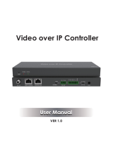
This Video over IP Controller is used to control and manage JPEG2000
IP products. It supports dual 100M network ports, which can realize dual-
network isolation of Control network and Multicast video distribution network.
Built-in Web GUI, TCP and RS-232 control are supported. It supports POE
function and wide-band 12V IR signal receiving. Since the demand of IP
products is daily increased in the current market, the IP Controller will be
widely applied in more and more different scenarios.
4. Specifications
5. Operation Controls and Functions
Network Bandwidth 100M
Transmission
Distance
Technical
Metal Enclosure
Dimensions
Housing
2 x 100M LAN [RJ45 connector] [VIDEO LANsupportPOE]
1 x IR IN [3.5mm audio jack, 12V level]
1 x DIGITAL I/O [6-pin 3.81mm phoenix connector]
1 x RS-232 [3-pin 3.81mm phoenix connector]
204mm(W)×98mm(D)×21mm(H)
Control Ports
12V/1A
4.5W
0°C ~ 40°C / 32°F ~ 104°F
-20°C ~ 60°C / -4°F ~ 140°F
Power Supply
Operating
Temperature
Storage Temperature
Relative Humidity 20~90% RH (non-condensing)
Power Consumption
100m CAT 5E/6/6A/7
BlackColor
Weight
5.1 Front Panel
123
2/29
RESET
POWER STATUS
509g
8765
No. Function DescriptionName
1 2 4
1 RESET Button Press and hold this button (about 10 seconds) until Status
LED starts flashing, Controller will be reset automatically.
2 POWER LED The red LED will light on when the Controller is powered on.
3 STATUS LED
The status LED will flash in yellowish-green every 1 second
until Controller boots up completely and Control LAN is
ready, then it becomes solid.
3/29
3
5.2 Rear Panel
No. Function DescriptionName
1 DC 12V DC 12V/1A power input port.
2VIDEO LAN
(POE)
100M Video LAN port, supporting POE function.
Note: When POE is enabled, DC 12V/1A power supply is
not required.
3CONTROL
LAN The TCP/IP control network port.
4MCU/Normal
DIP Switch
Normal mode (Default): The RS-232 port is used for serial
port commands control.
MCU mode: The RS-232 port is used for MCU software
upgrade.
53-pin Phoenix
Connector RS-232 serial communication port.
66-pin Phoenix
Connector
4 channel I/O level outputs, 1 channel grounding,
1 channel power supply to the outside.
7IO LEVEL
DIP Switch
Used to control I/O level output and VOUT voltage.
Switch to left: 5V I/O level output, VOUT is 5V.
Switch to right: 12V I/O level output, VOUT is 12V.
8IR IN 12V IR signal input port.
DC 12V
IO1
IO2
IO3
IO4
5V 12V
IR IN
IO LEVEL
VOUT
NORMAL
MCU
5.3 IR Pin Definition
IR RECEIVER
Power 12V
IR RECEIVER
6. Rack Mounting Instruction
This Controller can be mounted in a standard 6U rack (Please contact your
supplier for 6U rack sale). The mounting steps are as follows:
6.1 6U Rack Mounting
Step 1: Use included screws to fix two mounting ears on the Controller, as
shown in the figure below:
4/29
5 /29
Step 2: Insert the Controller with mounting ears into a 6U rack (up to 10
units can be installed vertically), as shown in the figure below:
Step 3: Use screws to fix mounting ears on the rack to complete the
mounting, as shown in the figure below:
6.2 1U Rack Mounting
This Controller also can be mounted in a standard 1U rack (up to 4 units can
be installed horizontally). The mounting steps are as follows:
Step 1: Stack two Controllers on top of each other, then use included screws
to fix two 1U rack panels on the Controllers, as shown in the figure below:
6 /29
Step 2: Fix two 1U rack panels on another two stacked Controllers in the
same way, then use screws to fix two 1U rack panels together, as shown
in the figure below:
Step 3: Fasten screws between two 1U rack panels, so that four Controllers
are mounted in a 1U rack, as shown in the figure below:
7. Web GUI User Guide
You can use Controller’s Web GUI to control all IP products at the Switch.
The operation method is shown as below:
7/29
Step 1: Input the Controller’s default IP address (192.168.0.225) or the URL
(http://controller.local) into the Web browser address bar on the PC to enter the
Web GUI login interface.
Select the initial username (admin) and input the initial password (1234) on
the above login interface. Then, click “Log In” to enter the Web GUI interface.
For the first time, you need to setup the project, as shown in the following
figure:
7.1 Preparation before Entering the System
8/29
Step 2: Click the “Close” button to load an existing project in web page
directly, or click “Next” button to go to the next step.
On this interface, you need to set the IP mode of Video LAN.
Mode 1: Automatically managed by Controller Box.
Please connect all the devices according to the following diagram.
Video Wall
4 × DEC
Controller Box
1G Ethernet Switch
DVD
DVD
DVD
DVD
TV
TV
TV
TV
ENC DEC
DEC
DEC
DEC
IR IN IR OUT USB HOST
RXTX
RS-232
RLRL
AUDIOIN OUT HDMI OUT HDMI IN
DC 12V
IR IN IR OUT USB HOST
RXTX
RS-232
RLRL
AUDIOIN OUT HDMI OUT HDMI IN
DC 12V
IR IN IR OUT USB HOST
RXTX
RS-232
RLRL
AUDIOIN OUT HDMI OUT HDMI IN
DC 12V
IR IN IR OUT USB HOST
RXTX
RS-232
RLRL
AUDIOIN OUT HDMI OUT HDMI IN
DC 12V
ENC
ENC
ENC
IR IN IR OUT
1 2 RLRLRXTX
RS-232 HDMI OUT
DC 12V AUDIOIN OUT
USB DEVICE 2.0
IR IN IR OUT
1 2 RLRLRXTX
RS-232 HDMI OUT
DC 12V AUDIOIN OUT
USB DEVICE 2.0
IR IN IR OUT
1 2 RLRLRXTX
RS-232 HDMI OUT
DC 12V AUDIOIN OUT
USB DEVICE 2.0
IR IN IR OUT
1 2 RLRLRXTX
RS-232 HDMI OUT
DC 12V AUDIOIN OUT
USB DEVICE 2.0
IR IN IR OUT
1 2 RLRLRXTX
RS-232 HDMI OUT
DC 12V AUDIOIN OUT
USB DEVICE 2.0
IR IN IR OUT
1 2 RLRLRXTX
RS-232 HDMI OUT
DC 12V AUDIOIN OUT
USB DEVICE 2.0
DC 12V
IO1
IO2
IO3
IO4
5V 12V
IR IN
IO LEVEL
VOUT
NORMAL
MCU
PC
TP-LINK
Router (optional)
9/29
If you select “Automatically add Encoders and Decoders to project”, and
click the “Scan” button to enter the Project page. All the connected devices
will be listed in the Current Devices list.
Click the “Next” button and wait for the completion to enter the interface as
shown in the figure below.
Then click “Stop Scan & Auto Assign” to stop search.
If you select “List all discovered Encoders and Decoders”, and click the “Scan”
button to enter the Project page. All the connected devices will be listed in the
Unassigned Devices list.
Click “Stop Scan” to stop search. Then the “Add All” buttons and “Add” buttons
behind Unassigned Encoders and Unassigned Decoders in the figure below
will become operable
At this time, you can click the “Add” button behind each unregistered Encoder
or Decoder to add the device to the project one by one, or click the “Add All”
button to add all Encoders or Decoders to the project.
Encoders and Decoders that have been added to the project will appear in
the Current Devices list, as shown in the figure below.
10/29
Mode 2: DHCP mode.
Please connect all the devices according to the following diagram.
Video Wall
4 × DEC
Controller Box
1G Ethernet Switch
DVD
DVD
DVD
DVD
TV
TV
TV
TV
ENC DEC
DEC
DEC
DEC
IR IN IR OUT USB HOST
RXTX
RS-232
RLRL
AUDIOIN OUT HDMI OUT HDMI IN
DC 12V
IR IN IR OUT USB HOST
RXTX
RS-232
RLRL
AUDIOIN OUT HDMI OUT HDMI IN
DC 12V
IR IN IR OUT USB HOST
RXTX
RS-232
RLRL
AUDIOIN OUT HDMI OUT HDMI IN
DC 12V
IR IN IR OUT USB HOST
RXTX
RS-232
RLRL
AUDIOIN OUT HDMI OUT HDMI IN
DC 12V
ENC
ENC
ENC
IR IN IR OUT
1 2 RLRLRXTX
RS-232 HDMI OUT
DC 12V AUDIOIN OUT
USB DEVICE 2.0
IR IN IR OUT
1 2 RLRLRXTX
RS-232 HDMI OUT
DC 12V AUDIOIN OUT
USB DEVICE 2.0
IR IN IR OUT
1 2 RLRLRXTX
RS-232 HDMI OUT
DC 12V AUDIOIN OUT
USB DEVICE 2.0
IR IN IR OUT
1 2 RLRLRXTX
RS-232 HDMI OUT
DC 12V AUDIOIN OUT
USB DEVICE 2.0
IR IN IR OUT
1 2 RLRLRXTX
RS-232 HDMI OUT
DC 12V AUDIOIN OUT
USB DEVICE 2.0
IR IN IR OUT
1 2 RLRLRXTX
RS-232 HDMI OUT
DC 12V AUDIOIN OUT
USB DEVICE 2.0
DC 12V
IO1
IO2
IO3
IO4
5V 12V
IR IN
IO LEVEL
VOUT
NORMAL
MCU
Router
TP-LINK
11/29
PC
TP-LINK
Router (optional)
Video Wall
4 × DEC
Controller Box
1G Ethernet Switch
DVD
DVD
DVD
DVD
TV
TV
TV
TV
ENC DEC
DEC
DEC
DEC
IR IN IR OUT USB HOST
RXTX
RS-232
RLRL
AUDIOIN OUT HDMI OUT HDMI IN
DC 12V
IR IN IR OUT USB HOST
RXTX
RS-232
RLRL
AUDIOIN OUT HDMI OUT HDMI IN
DC 12V
IR IN IR OUT USB HOST
RXTX
RS-232
RLRL
AUDIOIN OUT HDMI OUT HDMI IN
DC 12V
IR IN IR OUT USB HOST
RXTX
RS-232
RLRL
AUDIOIN OUT HDMI OUT HDMI IN
DC 12V
ENC
ENC
ENC
IR IN IR OUT
1 2 RLRLRXTX
RS-232 HDMI OUT
DC 12V AUDIOIN OUT
USB DEVICE 2.0
IR IN IR OUT
1 2 RLRLRXTX
RS-232 HDMI OUT
DC 12V AUDIOIN OUT
USB DEVICE 2.0
IR IN IR OUT
1 2 RLRLRXTX
RS-232 HDMI OUT
DC 12V AUDIOIN OUT
USB DEVICE 2.0
IR IN IR OUT
1 2 RLRLRXTX
RS-232 HDMI OUT
DC 12V AUDIOIN OUT
USB DEVICE 2.0
IR IN IR OUT
1 2 RLRLRXTX
RS-232 HDMI OUT
DC 12V AUDIOIN OUT
USB DEVICE 2.0
IR IN IR OUT
1 2 RLRLRXTX
RS-232 HDMI OUT
DC 12V AUDIOIN OUT
USB DEVICE 2.0
DC 12V
IO1
IO2
IO3
IO4
5V 12V
IR IN
IO LEVEL
VOUT
NORMAL
MCU
PC
TP-LINK
Router (optional)
Select “DHCP Mode” on the interface shown below, and click “Next”.
The rest of the steps are the same as the Mode 1 operation.
Mode 3: Static IP mode by manual settings.
Please connect all the devices according to the following diagram.
12/29
Select “Static IP mode by manual settings” on the interface shown below, and
click “Next”.
After entering the interface shown in the figure below, manually set the IP
address, subnet mask and gateway of the Video LAN.
13/29
Note:
It’s strongly recommended to use different IP network domain from Control
LAN port.
After the progress reaches 100%, enter the interface as shown in the figure
below.
On this interface, you can set the IP address range of Encoders and Decoders.
After the setting is complete, click the “Next” button to enter the interface
as shown in the figure below.
The rest of the steps are the same as the Mode 1 operation.
14/29
15/29
Preview Page
On this page, you can preview the Encoder/Decoder by clicking the drop-
down list on the right side.
7.2 Functions and Operation
Matrix Control Page
Encoders: Display all the current Encoders. The text in the figure is the
name of the device.
Decoders: Display all the current Decoders. The text on the first line is
the name of the Decoder, and the text on the second line refers to the
Encoder where the signal resource is from.
Operating Instructions:
(1) If an Encoder shows “No Signal”, it means that the Encoder cannot be
dragged.
(2) If there is an image on an Encoder, it means that the Encoder can be
dragged. As shown in the figure above, if an Encoder is dragged to the
place where the red arrow points to, all Decoders will share the same
signal resource from this Encoder; if an Encoder is dragged to the place
where the blue arrow points to, only the indicated Decoder can receive
signals from this Encoder.
Operating Instructions:
(1) Click “Display ID” to display the ID number of the Decoders.
(2) Click “Save Project” to save the project file (config_file.json), so that you
can use the saved project next time without scanning devices again.
(3) Click “Clear Project” to clear the current project, then you will need to
setup devices again.
(4) Click “Scan” to search devices that do not appear in the current project;
Click “Stop Scan”, then it will stop searching.
16/29
Project Page
Current Devices: Devices that have been added to the current project.
Unassigned Devices: Devices not added to the current project.
(5) Click “Configuration & Scan” to search new devices automatically and
add to the current project.
Operating Instructions:
(1) Click “Refresh” to refresh the data of the current Encoders.
(2) Click the drop-down list of EDID to set the current Encoder’s EDID.
(3) Click the drop-down list of Audio Selection to set the current Encoder’s
audio output.
(4) Click the icon on the left of ID to check the detail information about the
current Encoder, as shown in below:
17/29
Encoders Page
ID: The ID of the current device. (Note: ID is not duplicated.)
Name: The name of the current device. (Note: Name is not duplicated.)
MAC Address: The MAC Address of the current device.
IP Address: The IP Address of the current device.
Firmware: The Firmware version No. of the current device.
Status: The status (online or offline) of the current device.
EDID: The EDID of the current device.
Audio Selection: The Audio Selection of the current device.
18/29
On this page, you can setup the current Encoder as required.
  • Page 1 1
  • Page 2 2
  • Page 3 3
  • Page 4 4
  • Page 5 5
  • Page 6 6
  • Page 7 7
  • Page 8 8
  • Page 9 9
  • Page 10 10
  • Page 11 11
  • Page 12 12
  • Page 13 13
  • Page 14 14
  • Page 15 15
  • Page 16 16
  • Page 17 17
  • Page 18 18
  • Page 19 19
  • Page 20 20
  • Page 21 21
  • Page 22 22
  • Page 23 23
  • Page 24 24
  • Page 25 25
  • Page 26 26
  • Page 27 27
  • Page 28 28
  • Page 29 29
  • Page 30 30
  • Page 31 31

Altimium ALT-IPC460 User manual

Type
User manual
This manual is also suitable for

Ask a question and I''ll find the answer in the document

Finding information in a document is now easier with AI