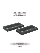
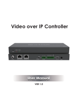
VigilLink VL-IPS4KCFT-1 User manual

Category
Network switches
Type
User manual

The VigilLink VL-IPS4KCFT-1 is a powerful SDVoE-compliant transceiver that supports 4K@60Hz 4:4:4 video with zero-frame latency and features such as video wall, multiview, and H.264/H.265 secondary streaming for preview purposes. It offers flexible connectivity options with both copper and fiber ports and allows for seamless switching and matrix routing.

The VigilLink VL-IPS4KCFT-1 is a powerful SDVoE-compliant transceiver that supports 4K@60Hz 4:4:4 video with zero-frame latency and features such as video wall, multiview, and H.264/H.265 secondary streaming for preview purposes. It offers flexible connectivity options with both copper and fiber ports and allows for seamless switching and matrix routing.

VL-IPS4KCFT-1
10G SDVoE HDMI 4K60 4:4:4 over IP w/Videowall and multiview
with USB 2.0 Cooper/Fiber Transceiver
VER 1.1
Thank you for purchasing this product
For optimum performance and safety, please read these instructions carefully
before connecting, operating, or adjusting this product. Please keep this manual
for future reference.
A surge protection device recommended
This product contains sensitive electrical components that may be damaged
by electrical spikes, surges, electric shocks, lightning strikes, etc. The use of
surge protection systems is highly recommended to protect and extend the
life of your equipment.
Table of Contents
1. Introduction. ....................................................................................... 1
2. Features. ............................................................................................. 1
3. Package Contents. ............................................................................ 2
4. Specifications. .................................................................................... 2
5. Operation Controls and Functions. ................................................... 4
5.1 Front Panel. ................................................................................... 4
5.2 Rear Panel. .................................................................................... 5
5.3 IR Pin Definition. ............................................................................ 6
6. Rack Mounting Instruction. ................................................................ 6
6.1 6U Rack Mounting. ....................................................................... 6
6.2 1U Rack Mounting. ....................................................................... 8
7. Preview Stream Introduction. ............................................................ 9
7.1 Connecting Web for Control. ....................................................... 9
7.2 VLC Media Player Instruction ....................................................... 14
8. Switch Model ...................................................................................... 17
9. SDVoE System Control. ....................................................................... 18
10. Application Example. ...................................................................... 18
1 / 19
1. Introduction
This transceiver is an SDVoE-Compliant, All-In-One AV over IP solution that
provides the highest-quality, uncompressed 4K and zero-frame latency audio/
video extension over a standard 10G Copper or Fiber Network Switch with
instant switching, Video Wall, and Multiview functions. It can transfer advanced
HDMI content such as HDR (high dynamic range), full color-depth, and multi-
channel HD Bitstream audio. Flexible transceiver design (one box can be set
to encoder or decoder) is much more convenient in a real installation site and
inventory control. Its built-in Secondary Stream supports a high-quality,
bandwidth configurable H.264/H.265 compression video stream for portable
device preview purposes. Multiple control and data signals can be
simultaneously transmitted with audio and video, including bi-directional IR,
RS-232, USB KVM, CEC, and 1G Ethernet.
2. Features
HDMI 2.0b and HDCP 2.2 compliant
Support video resolution up to 4K@60Hz 4:4:4, 18Gbps video bandwidth
Flexible transceiver design (Encoder, Decoder, Copper and Fiber ports
within a single box)
Encoder or Decoder mode can be set via Button or API
Automatic detection of Fiber and Copper ports (priority can be set)
Encoder supports HDMI Loop out
Support HDR10, Dolby Vision, HLG, 3D as well
Support full HDMI audio formats, up to Dolby TrueHD, Dolby Atmos and
DTS-HD, DTS:X
Support Zero-Frame latency operating mode
Support signal extension, seamless switching, Matrix, Video Wall up to
9x9 and Multiview up to 25 windows
Flexible audio routes control including bidirectional analog audio
transmissions between Encoder and Decoder
Built-in H.264/H.265 Secondary Stream (SS) for preview
Support Secondary Stream VLAN tagging and parameters configuration
Support bi-directional IR and RS-232 control signal pass-through
Support USB2.0 (KVM), CEC routing control
Support IR, RS-232, TCP/IP, Web GUI control
Standard POE supported (802.3at PD device)
10G managed network switch
2 / 19
3. Package Contents
1 x SDVoE Transceiver
1 x 12V IR Receiver cable (1.5 meters)
1 x IR Blaster cable (1.5 meters)
1 x 4-pin 3.81mm phoenix connector
1 x 12V/2.5A Locking power adapter
2 x Mounting ears
4 x Machine screws (KM3*6)
1 x User Manual
MAC Address Label (sticked on the back of the product):
MAC 1: SDVoE MAC address
MAC 2: USB2.0 MAC address
MAC 3: Secondary Stream (SS) Module MAC address
4. Specifications
Technical
HDMI Compliance
HDMI 2.0b
HDCP Compliance
HDCP 2.2
Video Bandwidth
18Gbps
Input Format
10GBaseT
Network Video
Bandwidth
10G
Video Resolution
Up to 4K@60Hz 4:4:4
Color Space
RGB, YCbCr 4:4:4 / 4:2:2 / 4:2:0
Color Depth
Full Color-Depth
HDR
HDR, HDR 10, HDR10+, Dolby Vision, HLG
HDMI Audio Formats
LPCM, Dolby Digital/Plus/EX, Dolby True HD,
Dolby Atmos, DTS, DTS-EX,DTS-96/24, DTS High
Res, DTS-HD Master Audio, DSD, DTS:X
Analog Audio
Formats
Left and Right stereo analog audio
Transmission
Distance
100M (CAT6A/7) / 90M(CAT6)
3 / 19
ESD Protection
Human body model ±8kV (Air-gap discharge) &
±4kV (Contact discharge)
Connection
Input ports
1 x HDMI IN [Type A, 19-pin female]
1 x USB 2.0 HOST [Type B, 4-pin female]
1x IR IN [3.5mm Jack]
1x AUDIO IN [3.5mm Jack]
1 x RS-232 [4-pin phoenix connector]
Output ports
1 x HDMI OUT [Type A, 19-pin female]
1x AUDIO OUT [3.5mm Jack]
1 x IR OUT [3.5mm Jack]
2 x USB 2.0 DEVICE [Type-A, 4pin female]
Network ports
1 x 10G BASE-T [RJ45 jack]
1 x 10G SFP+ [Fiber slot]
1 x 1G LAN [RJ45 jack]
Mechanical
Housing
Metal Enclosure
Color
Black
Dimensions
204mm [W] x 134mm [D] x 21.5mm [H]
Weight
693g
Power Supply
Input: AC100 - 240V 50/60Hz,
Output: DC 12V/2.5A
(US/EU standards, CE/FCC/UL certified)
Power Consumption
≈13.5W
Operating
Temperature
32 - 104°F / 0 - 40°C
Storage Temperature
-4 - 140°F / -20 - 60°C
Relative Humidity
20 - 90% RH (no-condensing)
Resolution /
Cable Length
Feet / Meters
4K30 -
Feet / Meters
Feet / Meters
HDMI IN / OUT
32ft / 10M
50ft / 15M
The use of the “Premium High-Speed HDMI” cable is highly
recommended.
4 / 19
5. Operation Controls and Functions
5.1 Front Panel
No.
Name
Function Description
1
RESET button
Restore default settings button. Press and hold this button
for 5 seconds in the power-on state to restore the default
settings.
2
POWER LED
(Red)
When the product is powered on, the red power LED will be
on.
3
STATUS LED
(Green)
System status indicator.
Light on: The system is running normally.
Light flashing/light off Program firmware lacking or
hardware error.
4 LINK LED
(Green)
10G network connection indicator.
Light on 10G network port is connected with the device.
Light off: 10G network port is not connected with the device.
5
VIDEO LED
(Green)
Video signal detection indicator.
ENC mode: Indicator lighting on means video input is detected.
DEC mode: Indicator lighting on means that HDMI OUT has
video signal output.
6
USB LED
(Green)
USB connection indicator.
Light flashing: The product is connected with USB devices,
and there is data transmission.
Light off: The product is not connected to USB devices.
7
ENC LED
(Green)
When the device is in ENC mode, the ENC LED is always on.
8
DEC LED
(Green)
When the device is in DEC mode, the DEC LED is always on.
9 MODE button Mode switch button. Press and hold the button for 5 seconds to
switch ENC or DEC mode.
10 USB DEVICES
port
USB device ports. Connect to mouse, keyboard, or U Disk
when the product is in DEC mode.
11
USB HOST
port
USB HOST input port. Connect to PC when the product is in
ENC mode.
5 / 19
IR OUT port
Description of ENC/DEC LED: (1) When the device is powered on, the ENC/DEC LED
flashes for about 15 seconds, and then keeps on, indicating the current ENC/DEC mode.
Press and hold the MODE button for 5 seconds to switch to another mode. The
corresponding ENC/DEC LED flashes for about 30 seconds and then stays on, indicating
that the mode is switched successfully.
(2) The user can also turn on the SHOW ME mode of the device by the Controller box.
At this time, the ENC/DEC LED flashes to indicate the current corresponding ENC/DEC
device, so that the user can easily find the device.
5.2 Rear Panel
No.
Name
Function Description
1
DC 12V
DC 12V power input port.
2
RS-232
Connect to PC or control system with a 4-pin phoenix
connector cable for RS-232 signal pass-through.
‘12V’ means that the product can supply power to the
outside.
3
IR IN port
IR signal input port.
4
IR OUT port
IR signal output port.
5 HDMI IN port
HDMI signal input port (ENC). Connect to HDMI source
devices such as DVD or Set-top box with HDMI cable.
6
HDMI OUT port
HDMI signal output port.
ENC mode: Used to loop out HDMI IN signal.
DEC mode: Used to output remote Encoder video stream
signal.
7 10G BASE-T port
10G network cable port. Connect to 10G Switch for video
transmission.
8 SFP+ port
10G network optical fiber port. Connect to 10G Switch for
video transmission.
9
1G LAN port
1G network port
.
Connect to the network port of the
corresponding application, such as 1G Ethernet or
Secondary Stream transmission.
6 / 19
10
AUDIO IN
Analog audio input port. Used for stereo analog audio
transmission, Secondary Stream audio embedding, and
HDMI audio embedding.
11 AUDIO OUT
Analog audio output port. Used to output HDMI extracted
stereo audio or output remote stereo analog audio signal.
5.3 IR Pin Definition
6. Rack Mounting Instruction
6.1 6U Rack Mounting
This transceiver can be mounted in a standard 6U rack (Please contact your
supplier for a 6U rack sale). The mounting steps are as follows:
Step 1: Use included screws to fix two mounting ears on the transceiver, as
shown in the figure below:
7 / 19
Step 2: Insert the transceiver with mounting ears into a 6U rack (up to 10
units can be installed vertically), as shown in the figure below:
Step 3: Use screws to fix mounting ears on the rack to complete the mounting,
as shown in the figure below:
8 / 19
6.2 1U Rack Mounting
This transceiver also can be mounted in a standard 1U rack (up to 4 units can
be installed horizontally). The mounting steps are as follows:
Step 1: Stack two transceivers on top of each other, then use included screws
to fix two 1U rack panels on the transceivers, as shown in the figure below:
Step 2: Fix two 1U rack panels on another two stacked transceivers in the
same way, then use screws to fix two 1U rack panels together, as shown in
the figure below:
Step 3: Fasten screws between two 1U rack panels, so that four transceivers
are mounted in a 1U rack, as shown in the figure below:
9 / 19
1
169 168 1 30
0
7. Preview Stream Introduction
7.1 Connecting Web for Control
This transceiver supports playing Secondary Stream on computer through the
corresponding software such as VLC media player, simultaneously you can
access the build-in Web GUI to configure the Secondary Stream.
The operation method shows as below.
Step 1: Connect the transceiver (in Encoder mode) with a PC, HDMI source
device and power supply. The connection diagram is shown as below.
Step 2: Set the PC’s IP address to be 169.254.100.100, and the Subnet mask
to be 255.255.0.0.
10 / 19
Step 3: Install a bonjour protocol checking tool (such as zeroconf
Service Browser) on PC to find the IP address of the Encoder.
Take zeroconf Service Browser as an example. After opening the software,
you can select “Workgroup Manager” in Services of Browser, select
the Host name in Service-Instances, and find the IP address in the Address
item in of Instance-Info.
Notes:
(1) The window in the lower left corner displays the Host names of all SS
devices in the current network.
(2) The window in the lower right corner displays the Host name, IP address
and Port number of the selected SS device.
(3) The Host name of Encoder starts with AVP-ENC; the Host name of Decoder
starts with AVP-DEC.
11 / 19
Step 4: Set the PC’s IP address to the same network segment as the IP
address of the Encoder Secondary Stream (SS). (If these two IP addresses are
in the same network segment, you can skip this step.)
Step 5: Input the IP address of the Encoder Secondary Stream (SS) found
through the bonjour protocol checking tool into the web browser on a PC.
The following login interface will appear.
Please select the fixed user name “admin”, and Input the default password
“admin”. Then click “Log In” to enter the Status page.
12 / 19
Status Page
The Status page provides basic information about the installed firmware
version and the network settings.
Video Page
On the Video page, you can set the Mainstream and Sub-stream separately.
The encoding Format can be set to H.265/H.264 according to the decoding
protocol used in the 3rd party software which decodes the Secondary Stream.
Pull the drop-down box to select it to take effect.
The Resolution of the Mainstream includes Auto, Horizontal, and Vertical. If
Auto is set to ON, the resolution will follow the input resolution. At this time,
Horizontal and Vertical display the current input resolution and are grayed out
13 / 19
and cannot be set. If Auto is set to OFF, then Horizontal and Vertical can be
set to the resolution of the Mainstream encoding. The horizontal range is
960~1920, the vertical range is 540~1080, and it needs to be an even number.
Click the “Apply” button to take effect.
The Resolution of the Sub Stream includes Horizontal and Vertical. Horizontal
and Vertical can be set to the resolution of the Sub Stream encoding. The
horizontal range is 320~960, the vertical range is 180~540, and it needs to be
an even number. Click the “Apply” button to take effect.
Bitrate is used to set the bit rate of the encoding.
Setting Page
The setting page includes two parts: Network and Login.
The network can be set to Static or DHCP. When set to Static, you can enter IP
address, gateway, and subnet mask; When set to DHCP, the IP address,
gateway, and subnet mask are grayed out and cannot be edited. A DHCP server
(e.g. network router) that automatically assigns IP-related settings should be
installed in the system. Web Port is the port of the Web page. After setting, click
“Save” to take effect. After setting the IP address, the page will automatically
switch to the set IP address. Click Set Network Defaults”, and it will be restored to
the default DHCP state.
The Web login password can be changed on the “Login” part. Enter the old
password in “Old Password”, enter the new password in “New Password”, enter
the new password again in “Confirm Password”, and click the “Save” button to
take effect.
14 / 19
Update Page
The SOC Update column is used to upgrade firmware. Click the “Browse”
button to select the firmware, and then click “Update”. When the progress
bar reaches 100%, the upgrade completes and the machine restarts
automatically.
The IMG Update column is used to download the no-signal picture, click the
“Browse” button to select the picture in jpg format (the resolution of the picture
should be less than or equal to 1920x1080, and the width should be aligned
with 8, the height should be aligned with 2, and the size of the picture should
be less than 512kB), and then click “Update”. When the progress bar reaches
100%, the download completes, and the machine takes effect without
rebooting.
7.2 VLC Media Player Instruction
After the Web GUI is successfully connected, open the VLC media player on the
PC. Please see the following icon.
15 / 19
Click “Media > Open Network Stream”
After clicking the “Open Network Stream” option, the following page will
appear.
16 / 19
Enter a Mainstream or Substream network URL, then click “Play” button.
Stream
Network URL
Mainstream
rtsp://169.254.100.254/live/main/av_stream
Substream rtsp://169.254.100.254/live/sub/av_stream.
Note: The default IP address of Secondary Stream is 169.254.100.254. When
the IP address of the Encoder Secondary Stream (SS) found through the
bonjour protocol checking tool is different from the default IP address, please
use it instead of the default IP address.
On the VLC media player, you can check Secondary Mainstream or Sub
Stream settings that are configured on the “Video Page” (Please refer to “7.1
Connecting Web for Control” for details). Choose “Tools>Codec information”,
and a pop-up window will display and show you Stream information, as shown
in the figure below.
Choose “Tools>Codec information>Statistics” to check current Bitrate.
Please see the following picture.
17 / 19
Note: The Bitrate is floating up and down when you check it. This is a
normal phenomenon.
8. Switch Model
A network Switch used to set up the system should support the below features:
1. Type of layer 3/managed network Switch.
2. 10 Gigabit bandwidth.
3. IGMP version 2 supported.
4. IGMP version 2 snooping enabled.
5. Filter/Drop unregistered multicast traffic.
6. Disable unregistered multicast flooding.
7. Enable fast leave support.
The following Switch models are highly recommended.
Manufacturer
Model Number
Netgear ProSAFE PLUS XS708E
Netgear
ProSAFE M4300 Intelligent Edge Series
Netgear
ProSAFE Smart XS712T
Netgear
M7300-24XF XSM7224S
Arista Networks
7050X Series
18 / 19
9. SDVoE System Control
This transceiver can be controlled by Controller Box or a third-party
controller. For details of SDVoE system control, please refer to SDVoE
Controller Box user manual.
10. Application Example
  • Page 1 1
  • Page 2 2
  • Page 3 3
  • Page 4 4
  • Page 5 5
  • Page 6 6
  • Page 7 7
  • Page 8 8
  • Page 9 9
  • Page 10 10
  • Page 11 11
  • Page 12 12
  • Page 13 13
  • Page 14 14
  • Page 15 15
  • Page 16 16
  • Page 17 17
  • Page 18 18
  • Page 19 19
  • Page 20 20
  • Page 21 21

VigilLink VL-IPS4KCFT-1 User manual

Category
Network switches
Type
User manual

The VigilLink VL-IPS4KCFT-1 is a powerful SDVoE-compliant transceiver that supports 4K@60Hz 4:4:4 video with zero-frame latency and features such as video wall, multiview, and H.264/H.265 secondary streaming for preview purposes. It offers flexible connectivity options with both copper and fiber ports and allows for seamless switching and matrix routing.

Ask a question and I''ll find the answer in the document

Finding information in a document is now easier with AI