Page is loading ...


Thank you for purchasing this product
For optimum performance and safety, please read these instructions carefully
before connecting, operating or adjusting this product. Please keep this manual
for future reference.
Surge protection device recommended
This product contains sensitive electrical components that may be damaged
by electrical spikes, surges, electric shock, lighting strikes, etc. Use of surge
protection systems is highly recommended in order to protect and extend the
life of your equipment.
Table of Contents
1. Introduction...........................................................................................1
2. Features. ................................................................................................1
3. Package Contents. ..............................................................................2
4. Specifications. ......................................................................................3
5. Operation Controls and Functions. .....................................................5
5.1 Encoder Panel. ...............................................................................5
5.2 Decoder Panel................................................................................9
5.3 IR Pin Definition. ..............................................................................14
6. Rack Mounting Instruction. ..................................................................14
6.1 6U V2 Rack Mounting. ....................................................................14
6.2 1U V2 Rack Mounting. ....................................................................16
7. MJPEG Substream Operation Introduction. .......................................17
7.1 MJPEG Substream Preview/Configuration via Web Page. .........17
7.2 VLC Media Player Instruction ........................................................20
8. Switch Model ........................................................................................23
9. 4K over IP System Control. ...................................................................24
10. Application Example. ........................................................................24

1/25
1. Introduction
This product is based on JPEG2000 technology. It integrates Copper port
and Fiber port within a single box. Encoder input supports up to 4K60 4:4:4,
audio embedding or extracting. Decoder output supports up to 4K60 4:4:4,
audio extracting. The product supports ARC/eARC/SPDIF/Analog audio return
function, also supports USB2.0/KVM/Camera, 1G Ethernet, bidirectional RS-
232, two-way IR and POE function. Guest mode controls of RS-232, IR, CEC
are supported. Built-in two channel RELAY ports and two channel I/O ports
for contact control.
Built-in MJPEG Substream which supports plenty API commands to achieve
flexible configurations is useful for 3rd party control Apps to preview video
content.
The system is based on Linux for software development, provides flexible
control methods, that are based on the intelligent networking of 1G Ethernet
Switch.
2. Features
☆ HDMI 2.0b, HDCP 2.2 compliant
☆ Support 18Gbps video bandwidth
☆ Input and output video resolution is up to 4K60 4:4:4
☆ Signal transmission distance can be extended up to 328ft / 100m via
CAT5E/6/6A/7 cable
☆ Transmit video, analog/digital audio, IR, RS-232, CEC and USB over
Ethernet
☆ Integrate both Copper and Fiber ports redundancy
☆ ARC/eARC/SPDIF/Analog audio return function
☆ Channel configuration via front panel buttons and LED screen
☆ Built-in two channel RELAY ports and two channel I/O ports for contact
control
☆ Support unicast and multicast functions
☆ Support point-to-point, video matrix and video wall functions (video wall
supports up to 9x9)
☆ Intelligent video wall group management
☆ Support MJPEG Substream real-time preview
☆ 1G Ethernet Switch

2/25
☆ Support POE function
☆ Built-in Web-GUI control, Telnet and SSH as well
☆ HDMI audio formats: LPCM 2.0/5.1/7.1CH, Dolby Digital/Plus/EX, Dolby
True HD, DTS, DTS-96/24, DTS-EX DSD, DTS High Res, DTS-HD Master
☆ Smart networking design for easy and flexible installation
3. Package Contents
or
Qty
Item
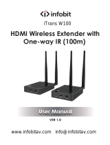
1
4K60 over IP 1GbE Encoder
1
IR Receiver cable (1.5 meters)
1
IR Blaster cable (1.5 meters)
3
3-pin 3.81mm Phoenix
connector
2
4-pin 3.81mm Phoenix
connector
1
12V/2.5A Locking Power
adapter
2
Mounting ear
4
Machine screw (KM3*4)
1
User Manual
Qty
Item
1
4K60 over IP 1GbE Decoder
1
IR Receiver cable (1.5 meters)
1
IR Blaster cable (1.5 meters)
3
3-pin 3.81mm Phoenix
connector
2
4-pin 3.81mm Phoenix
connector
1
12V/2.5A Locking Power
adapter
2
Mounting ear
4
Machine screw (KM3*4)
1
User Manual

3/25
4. Specifications
Technical
HDMI Compliant
HDMI 2.0b
HDCP Compliant
HDCP 2.2
Video Bandwidth
18Gbps
Video Compression
Standard
JPEG2000
Video Network
Bandwidth
1G
Video Resolution
Up to 4K@60Hz 4:4:4
Color Depth
Input: 8/10/12-bit
Output: 8-bit
Color Space
RGB 4:4:4, YCbCr 4:4:4 / 4:2:2 / 4:2:0
HDMI Audio Formats
LPCM 2.0/5.1/7.1CH, Dolby Digital/Plus/EX, Dolby True HD,
DTS, DTS-96/24, DTS-EX DSD, DTS High Res, DTS-HD
Master
Transmission
Distance
100M CAT5E/6/6A/7
IR Level
Default 12V, optional 5V
IR Frequency
Wideband 20K - 60KHZ
ESD Protection
Human body model — ±8kV (Air-gap discharge) &
±4kV (Contact discharge)
Connection
Encoder
Input: 1 x HDMI IN [Type A, 19-pin female]
1 x L/R AUDIO IN [3-pin 3.81mm Phoenix connector]
Output: 1 x HDMI OUT [Type A, 19-pin female]
1 x L/R AUDIO OUT [3-pin 3.81mm Phoenix connector]
1 x SPDIF OUT [Optical audio connector]
Control: 1 x RS-232 [3-pin 3.81mm Phoenix connector]
1 x LAN (POE) [RJ45 jack]
1 x FIBER [Optical fiber slot]
1 x USB 2.0 HOST [Type B, 4-pin female]
2 x USB 2.0 DEVICE [Type-A, 4pin female]
2 x RELAYS [3.81mm Phoenix connector]
2 x DIGITAL IO [3.81mm Phoenix connector]
1 x IR IN [3.5mm Audio Jack]
1 x IR OUT [3.5mm Audio Jack]

4/25
Decoder
Input: 1 x SPDIF IN [Optical audio connector]
1 x L/R AUDIO IN [3-pin 3.81mm Phoenix connector]
Output: 1 x HDMI OUT [Type A, 19-pin female]
1 x L/R AUDIO OUT [3-pin 3.81mm Phoenix connector]
Control: 1 x RS-232 [3.81mm Phoenix connector]
1 x LAN (POE) [RJ45 jack]
1 x FIBER [Optical fiber slot]
2 x USB 1.1 DEVICE [Type-A, 4-pin female]
2 x USB 2.0 DEVICE [Type-A, 4-pin female]
2 x RELAYS [3.81mm Phoenix connector]
2 x DIGITAL IO [3.81mm Phoenix connector]
1 x IR IN [3.5mm Audio Jack]
1 x IR OUT [3.5mm Audio Jack]
Mechanical
Housing
Metal enclosure
Color
Black
Dimensions
Encoder/Decoder: 204mm [W] x 136mm [D] x 25.5mm [H]
Weight
Encoder: 631g, Decoder: 626g
Power Supply
Input: AC100 - 240V 50/60Hz,
Output: DC 12V/2.5A (US/EU standards, CE/FCC/UL certified)
Power Consumption
Encoder: 8.52W, Decoder: 7.08W (Max.)
Operating
Temperature
32 - 104°F / 0 - 40°C
Storage Temperature
-4 - 140°F / -20 - 60°C
Relative Humidity
20 - 90% RH (no condensing)
Resolution /
Cable Length
4K60 -
Feet / Meters
4K30 -
Feet / Meters
1080P60 -
Feet / Meters
HDMI IN / OUT
16ft / 5M
32ft / 10M
50ft / 15M
The use of “Premium High Speed HDMI” cable is highly recommended.

5/25
5. Operation Controls and Functions
5.1 Encoder Panel
No.
Name
Function Description
1
RESET
After powering on the device, press and hold the RESET
button until the POWER LED and LINK LED flash at the same
time, release the button to reset the device to factory settings.
2
POWER LED
(Red)
▪ Light on: The system is powered on (with POE or DC power
supply).
▪ Light off: The system is powered off (without POE or DC power
supply).
3
LINK LED
(Green)
Connection status LED.
▪ Light on: Encoder and Decoder are connected through the
LAN(POE)/FIBER ports, and there is video signal transmitted to
the Decoder.
▪ Light flashes: Encoder and Decoder are connected through the
LAN(POE)/FIBER ports, but there is no video signal transmitted
to the Decoder.
▪ Light off: Encoder and Decoder are not connected through the
LAN(POE)/FIBER ports.
4
LED screen
Shows Encoder ID as default. Displays the corresponding
options of configuration functions during setting Encoder
configurations.
5
CH SELECT
Used to set Encoder ID and other settings.
6
USB 2.0 DEVICE
Connect to USB 2.0 devices.
7
USB HOST
USB-B connector for connecting a PC.
8
IR OUT
IR signal output port. The IR level can be set to 5V or 12V
(default) through the panel buttons.

6/25
9
IR IN
IR signal input port. The IR level can be set to 5V or 12V
(default) through the panel buttons.
10
RELAYS I
DIGITAL IO
VCC: Power output (12V or 5V configurable), maximum to 12V
@50mA, 5V@ 100mA loading. The default output is 12V.
RELAYS: 2 channel low-voltage relay ports, each group is
independent and isolated, maximum to 1A 30VDC loading.
Contacts are disconnected by default.
DIGITAL IO: 2 channel GPIO ports, for digital level signal output
control or input detection (up to 12V level detection). The output
control mode (default mode, low level as default output) or input
detection mode is configurable. The DIGITAL IO internal pull-up
voltage follows the VCC.
Output control mode:
a. The maximum withstand sink current is 50mA when outputting
low level.
b. When VCC is 5V and high level is output, the maximum
current driving capacity is 2mA.
c. When VCC is 12V and high level is output, the maximum
current driving capacity is 5mA.
Input detection mode:
a. When VCC is 5V, DIGITAL IO is pulled up to 5V internally
through a 2.2K ohm resistor.
b. When VCC is 12V, DIGITAL IO is pulled up to 12V internally
through a 2.2K ohm resistor.
11
RS-232
RS-232 serial port, supporting RS-232 command pass-through
and local serial port control.
12
AUDIO IN/OUT
AUDIO IN: Analog audio input port, the audio can be embedded into
the HDMI signal for pass-through over to HDMI output and audio
out on Decoder, or be loopout by the AUDIO OUT port on Encoder.
AUDIO OUT: Analog audio output port. It can output the audio
extracted from the HDMI IN port (in case of LPCM) . Also it can
output the audio transmitted from the AUDIO IN port of the
Decoder in unicast mode (point-to-point direct connection).
13
SPDIF OUT
SPDIF signal output port. It can output the ARC or SPDIF audio
returned from the Decoder when both the Encoder and Decoder
are correspondingly set to the ARC or SPDIF audio return mode
(Set through the Controller Box or API commands in Multicast
mode; Set through the front panel buttons in unicast mode).
14
HDMI OUT
HDMI local loop output port, connected to an HDMI display device
such as TV or monitor.
15
HDMI IN
HDMI signal input port, connected to an HDMI source device such
as Blu-ray Player or Set-top box with an HDMI cable.
16
FIBER
Connect with optical fiber module, and transmit signals to the
Decoder with an optical fiber cable directly or through a Switch.

7/25
17
LAN (POE)
1G LAN port, connect network Switch to form a distributed
system.
Note: When network switch delivers POE power supply, DC
12V adapter doesn't need to apply on the unit.
18
Data Signal
Indicator lamp
(Yellow)
▪ Light flashing: There is data transmission.
▪ Light off: There is no data transmission.
19
Link Signal
Indicator lamp
(Green)
▪ Light on: The network cable is connected normally.
▪ Light off: The network cable is not connected well.
20
DC 12V
The device can be powered via two methods:
▪ Local DC 12V/2.5A power supply
▪ POE from Network Switch. Device acts as PD mode.
When the Switch supports POE function, DC power supply
is not needed.
Operation description of the LED screen and CH SELECT buttons (For Encoder).
1, ENC ID: After the system is powered on, the Encoder’s LED screen will show the
ENC ID (000 by default if not set).
2, IP address: Press and hold the UP button for 5 seconds, the Encoder’s LED screen
will show in sequence “IPx", "xxx", "xxx", "xxx", "xxx", which are the IP mode and IP
address of Encoder.
3, Configuration mode: Press and hold UP + DOWN buttons at the same time for 5
seconds, then release to enter the configuration mode with “CFN” displaying on the
LED screen.
4, Device ID settings: After entering the configuration mode, press the UP/DOWN button
to enter the first page with the current ID number (e.g. 001) displaying on the LED
screen. Press and hold UP + DOWN buttons for 5 seconds, then release to enter the
ID settings mode, in which the ID number (e.g. 001) on the LED screen will flash
at 1Hz, then press the UP/DOWN button to select the device ID you desired (ID range:
000~767), then press and hold UP + DOWN buttons for 5 seconds to confirm the
setting and stop flashing.
Note: The device ID can not be modified in Controller Box mode.
5, EDID settings: After entering the configuration mode, press the UP/DOWN button
to enter the second page with “E00” (in which “E” refers to EDID, “00” to EDID ID) or
“COP” (which indicates copy EDID) displaying on the LED screen. Press and hold UP
+ DOWN buttons for 5 seconds, then release to enter the EDID settings mode, in which
the EDID ID number (e.g. E01) on the LED screen will flash at 1Hz, then press the UP/
DOWN button to select the EDID ID you desired, then press and hold UP + DOWN
buttons for 5 seconds to confirm the setting and stop flashing.
The corresponding EDID ID is as follows:

8/25
EDID ID
EDID Description
EDID ID
EDID Description
E00
1080P_Stereo_Audio_2.0_SDR
E12
4K2K60_420_Stereo_Audio_2.0_SDR
E01
1080P_DolbyDTS_5.1_SDR
E13
4K2K60_420_DolbyDTS_5.1_SDR
E02
1080P_HD_Audio_7.1_SDR
E14
4K2K60_420_HD_Audio_7.1_SDR
E03
1080I_Stereo_Audio_2.0_SDR
E15
4K2K60_444_Stereo_Audio_2.0_SDR
E04
1080I_DolbyDTS_5.1_SDR
E16
4K2K60_444_DolbyDTS_5.1_SDR
E05
1080I_HD_Audio_7.1_SDR
E17
4K2K60_444_HD_Audio_7.1_SDR
E06
3D_Stereo_Audio_2.0_SDR
E18
4K2K60_444_Stereo_Audio_2.0_HDR_10-bit
E07
3D_DolbyDTS_5.1_SDR
E19
4K2K60_444_DolbyDTS_5.1_HDR_10-bit
E08
3D_HD_Audio_7.1_SDR
E20
4K2K60_444_HD_Audio_7.1_HDR_10-bit
E09
4K2K30_444_Stereo_Audio_2.0_SDR
E21
DVI_1280x1024
E10
4K2K30_444_DolbyDTS_5.1_SDR
E22
DVI_1920x1080
E11
4K2K30_444_HD_Audio_7.1_SDR
E23
DVI_1920x1200
6, IR mode settings: After entering the configuration mode, press the UP/DOWN button
to enter the third page with “IR2” (in which “IR” refers to IR and “2” to 12V) displaying
on the LED screen. Press and hold UP + DOWN buttons for 5 seconds, then release
to enter the IR mode settings mode, in which the IR mode (IR1 or IR2) on the LED
screen will flash at 1Hz, then press the UP/DOWN button to select the IR mode, then
press and hold UP + DOWN buttons for 5 seconds to confirm the setting and stop
flashing. The corresponding IR mode options are as follows:
IR1: 5V IR wire
IR2: 12V IR wire
7, Audio return mode settings: After entering the configuration mode, press the UP/
DOWN button to enter the fourth page with “ARC/SPD/ANA” displaying on the LED
screen. Press and hold UP + DOWN buttons for 5 seconds, then release to enter the
audio return mode settings mode, in which the audio return mode (ARC/SPD/ANA) on
the LED screen will flash at 1Hz, then press the UP/DOWN button to select the mode,
then press and hold UP + DOWN buttons for 5 seconds to confirm the setting and stop
flashing. The corresponding audio return mode options are as follows:
ARC: eARC/ARC audio return
SPD: SPDIF audio return
ANA: Analog audio return
Note:
(1) The audio return mode can not be modified through front panel buttons in
Controller Box or Multicast mode.
(2) Only when both the Encoder and Decoder are correspondingly set to ARC/SPD/
ANA audio return mode in unicast mode, the audio return can be realized.

9/25
(3) When to use ARC, ARC audio amplifier on Encoder HDMI IN port and ARC TV on
Decoder HDMI OUT port should be used.
When to use eARC, eARC audio amplifier on Encoder HDMI IN port and eARC TV
on Decoder HDMI OUT port should be used.
8, IP mode settings: After entering the configuration mode, press the UP/DOWN button
to enter the fifth page with “IP1/IP2/IP3” displaying on the LED screen. Press and hold
UP + DOWN buttons for 5 seconds, then release to enter the IP mode settings mode,
in which the IP mode (IP1/IP2/IP3) on the LED screen will flash at 1Hz, then press the
UP/DOWN button to select the mode, then press and hold UP + DOWN buttons for 5
seconds to confirm the setting and stop flashing. The corresponding IP mode options
are as follows:
IP1: Static IP mode
IP2: DHCP IP mode
IP3: Auto IP mode
Note:
(1) The IP mode can not be modified in Controller Box mode.
(2) After entering various setting modes, you can hold down the DOWN button to exit
the current interface quickly, or if you do not perform any operation within 5 seconds,
it will automatically return to the previous interface.
5.2 Decoder Panel
No.
Name
Function Description
1
RESET
After powering on the device, press and hold the RESET
button until the POWER LED and LINK LED flash at the same
time, release the button to reset the device to factory settings.
2
POWER LED
(Red)
▪ Light on: The system is powered on (with POE or DC power
supply).
▪ Light off: The system is powered off (without POE or DC power
supply).

10/25
3
LINK LED
(Green)
Connection status LED.
▪ Light on: Encoder and Decoder are connected through the
LAN(POE)/FIBER ports, and there is video signal transmitted
from the Encoder.
▪ Light flashes: Encoder and Decoder are connected through the
LAN(POE)/FIBER ports, but there is no video signal transmitted
from the Encoder.
▪ Light off: Encoder and Decoder are not connected through the
LAN(POE)/FIBER ports.
4
LED screen
Shows the selected Encoder ID as default. Displays the
corresponding options of configuration functions during setting
Decoder configurations.
5
CH SELECT
Used to set Decoder ID and other settings.
6
USB 1.1 DEVICE
Connect to USB 1.1 devices, such as Keyboard or Mouse.
7
USB 2.0 DEVICE
Connect to USB 2.0 devices, such as USB flash disk or USB
Camera.
8
IR OUT
IR signal output port. The IR level can be set to 5V or 12V
(default) through the panel buttons.
9
IR IN
IR signal input port. The IR level can be set to 5V or 12V
(default) through the panel buttons.
10
RELAYS I
DIGITAL IO
VCC: Power output (12V or 5V configurable), maximum to
12V@50mA, 5V@ 100mA loading. The default output is 12V.
RELAYS: 2 channel low-voltage relay ports, each group is
independent and isolated, maximum to 1A 30VDC loading.
Contacts are disconnected by default.
DIGITAL IO: 2 channel GPIO ports, for digital level signal
output control or input detection (up to 12V level detection).
The output control mode (default mode, low level as default
output) or input detection mode is configurable. The DIGITAL
IO internal pull-up voltage follows the VCC.
Output control mode:
a. The maximum withstand sink current is 50mA when
outputting low level.
b. When VCC is 5V and high level is output, the maximum
current driving capacity is 2mA.
c. When VCC is 12V and high level is output, the maximum
current driving capacity is 5mA.
Input detection mode:
a. When VCC is 5V, DIGITAL IO is pulled up to 5V internally
through a 2.2K ohm resistor.
b. When VCC is 12V, DIGITAL IO is pulled up to 12V internally
through a 2.2K ohm resistor.

11/25
11
RS-232
RS-232 serial port, supporting RS-232 command pass-through
and local serial port control.
12
AUDIO IN/OUT
AUDIO IN: Analog audio input port, the audio can be transmitted
to Encoder AUDIO OUT in unicast mode (point-to-point direct
connection).
AUDIO OUT: Analog audio output port. It outputs the same audio
of that on HDMI OUT in case audio format is LPCM.
13
SPDIF IN
SPDIF signal input port.
14
HDMI OUT
HDMI signal output port, connected to an HDMI display device
such as TV or monitor.
15
FIBER
Connect with optical fiber module, and receive signals from the
Encoder with an optical fiber cable directly or through a Switch.
16
LAN (POE)
1G LAN port, connect network Switch to form a distributed
system.
Note: When network switch delivers POE power supply, DC
12V adapter doesn't need to apply on the unit.
17
Data Signal
Indicator lamp
(Yellow)
▪ Light flashing: There is data transmission.
▪ Light off: There is no data transmission.
18
Link Signal
Indicator lamp
(Green)
▪ Light on: The network cable is connected normally.
▪ Light off: The network cable is not connected well.
19
DC 12V
The device can be powered via two methods:
▪ Local DC 12V/2.5A power supply
▪ POE from Network Switch. Device acts as PD mode.
When the Switch supports POE function, DC power supply
is not needed.

12/25
Operation description of the LED screen and CH SELECT buttons (For Decoder).
1, ENC connection: After the system is powered on, the Decoder’s LED screen will
show 000 by default if not set. Directly press the UP/DOWN button to select the
channel ID of the connected Encoder (ID range: 000~767) to complete connection.
2, IP address: Press and hold the UP button for 5 seconds, the Decoder’s LED screen
will show in sequence “IPx", "xxx", "xxx", "xxx", "xxx", which are the IP mode and IP
address of Decoder.
3, Configuration mode: Press and hold UP + DOWN buttons at the same time for 5
seconds, then release to enter the configuration mode with “CFN” displaying on the
LED screen.
4, Device ID settings: After entering the configuration mode, press the UP/DOWN button
to enter the first page with the current ID number (e.g. 001) displaying on the LED
screen. Press and hold UP + DOWN buttons for 5 seconds, then release to enter the
ID settings mode, in which the ID number (e.g. 001) on the LED screen will flash
at 1Hz, then press the UP/DOWN button to select the device ID you desired (ID range:
000~767), then press and hold UP + DOWN buttons for 5 seconds to confirm the
setting and stop flashing.
Note: The device ID can not be modified in Controller Box mode.
5, Resolution settings: After entering the configuration mode, press the UP/DOWN
button to enter the second page with “S00” (in which “S” refers to Scaler and “00” to
resolution ID) displaying on the LED screen. Press and hold UP + DOWN buttons for
5 seconds, then release to enter the output resolution settings mode, in which the
resolution ID number (e.g. S00) on the LED screen will flash at 1Hz, then press the
UP/DOWN button to select the resolution ID you desired, then press and hold UP +
DOWN buttons for 5 seconds to confirm the setting and stop flashing.
The corresponding output resolution ID is as follows:
Resolution ID
Resolution Description
Resolution ID
Resolution Description
0
bypass
7
2160P50
1
1080P50
8
2160P60
2
1080P60
9
1280x1024
3
720P50
10
1360x768
4
720P60
11
1440x900
5
2160P24
12
1680x1050
6
2160P30
13
1920x1200

13/25
6, IR mode settings: After entering the configuration mode, press the UP/DOWN button
to enter the third page with “IR2” (in which “IR” refers to IR and “2” to 12V) displaying
on the LED screen. Press and hold UP + DOWN buttons for 5 seconds, then release
to enter the IR mode settings mode, in which the IR mode (IR1 or IR2) on the LED
screen will flash at 1Hz, then press the UP/DOWN button to select the IR mode, then
press and hold UP + DOWN buttons for 5 seconds to confirm the setting and stop
flashing. The corresponding IR mode options are as follows:
IR1: 5V IR wire
IR2: 12V IR wire
7, Audio return mode settings: After entering the configuration mode, press the UP/
DOWN button to enter the fourth page with “ARC/SPD/ANA” displaying on the LED
screen. Press and hold UP + DOWN buttons for 5 seconds, then release to enter the
audio return mode settings mode, in which the audio return mode (ARC/SPD/ANA) on
the LED screen will flash at 1Hz, then press the UP/DOWN button to select the mode,
then press and hold UP + DOWN buttons for 5 seconds to confirm the setting and stop
flashing. The corresponding audio return mode options are as follows:
ARC: eARC/ARC audio return
SPD: SPDIF audio return
ANA: Analog audio return
Note:
(1) The audio return mode can not be modified through front panel buttons in
Controller Box or Multicast mode.
(2) Only when both the Encoder and Decoder are correspondingly set to ARC/SPD/
ANA audio return mode in unicast mode, the audio return can be realized.
(3) When to use ARC, ARC audio amplifier on Encoder HDMI IN port and ARC TV on
Decoder HDMI OUT port should be used.
When to use eARC, eARC audio amplifier on Encoder HDMI IN port and eARC TV
on Decoder HDMI OUT port should be used.
8, IP mode settings: After entering the configuration mode, press the UP/DOWN button
to enter the fifth page with “IP1/IP2/IP3” displaying on the LED screen. Press and hold
UP + DOWN buttons for 5 seconds, then release to enter the IP mode settings mode,
in which the IP mode (IP1/IP2/IP3) on the LED screen will flash at 1Hz, then press the
UP/DOWN button to select the mode, then press and hold UP + DOWN buttons for 5
seconds to confirm the setting and stop flashing. The corresponding IP mode options
are as follows:
IP1: Static IP mode
IP2: DHCP IP mode
IP3: Auto IP mode
Note:
(1) The IP mode can not be modified in Controller Box mode.
(2) After entering various setting modes, you can hold down the DOWN button to exit
the current interface quickly, or if you do not perform any operation within 5 seconds,
it will automatically return to the previous interface.

14/25
5.3 IR Pin Definition
6. Rack Mounting Instruction
6.1 6U V2 Rack Mounting
This product can be mounted in a standard 6U V2 rack (Please contact your
supplier for 6U V2 rack sale). The mounting steps are as follows:
Step 1: Use included screws to fix two mounting ears on the product, as
shown in the figure below:

15/25
Step 2: Insert the product with mounting ears into a 6U V2 rack (6/8/10 units
can be installed vertically), as shown in the figure below:
Step 3: Use screws to fix mounting ears on the rack to complete the mounting,
as shown in the figure below:

16/25
6.2 1U V2 Rack Mounting
This product also can be mounted in a standard 1U V2 rack (2 units can be
installed horizontally). The mounting steps are as follows:
Step 1: Use included screws to fix two 1U V2 rack brackets on two products
respectively, as shown in the figure below:
Step 2: Use screws to fix two 1U V2 rack brackets together, as shown in the
figure below:
Step 3: Fasten screws between two 1U V2 rack brackets, so that two products
are mounted in a 1U V2 rack, as shown in the figure below:

17/25
7. MJPEG Substream Operation Introduction
7.1 MJPEG Substream Preview/Configuration via Web Page
The product supports playing MJPEG Substream on computer through the
corresponding software such as VLC media player, simultaneously you can
access the Web page to configure the MJPEG Substream.
Follow the steps below to preview and configure the MJPEG Substream.
Step 1: Connect the Encoder, Decoder and PC to the same Switcher, then
connect an HDMI source device and power supply. The connection diagram
is shown as below.
Step 2: Install a bonjour protocol checking tool (such as zeroconfService
Browser) on PC to find the IP address of the Encoder/Decoder.
Take zeroconfServiceBrowser as an example. After opening the software,
you can select “Workgroup Manager” in Services of Browser, select
the Host name in Service-Instances, and find the IP address in the Address
item in of Instance-Info.
LA
N

18/25
169 168 110 30
0
Note:
(1) The window in the lower left corner displays the Host names of all devices
in the current network.
(2) The window in the lower right corner displays the Host name, IP address
and Port number of the device.
(3) The Host name of Encoder starts with AST-ENC; the Host name of Decoder
starts with AST-DEC.
Step 3: Set the PC’s IP address to the same network segment with IP address
of the Encoder/Decoder found in step 2.
/