Page is loading ...

FORM #5702.01-120506 PRINTED IN U.S.A. PAGE 1 OF 6
SUPERLIFT SUSPENSION SYSTEMS
300 Huey Lenard Loop Rd.
West Monroe, Louisiana 71292
Phone: (318) 397-3000
Sales / Tech: 1-800-551-4955
FAX: (318) 397-3040
www.superlift.com
Superlift 2” lift system for 2007 and Newer
Jeep Wrangler (JK) 4WD
INSTALLATION INSTRUCTIONS
INTRODUCTION
Installation requires a professional mechanic. Prior to beginning, inspect the vehicles steering,
driveline, and brake systems, paying close attention to the suspension link arms and bushings,
anti-sway bars and bushings, tie rod ends, pitman arm, ball joints and wheel bearings. Also check
the steering sector-to-frame and all suspension-to-frame attaching points for stress cracks. The
overall vehicle must be in excellent working condition; repair or replace all worn parts.
Read instructions several times before starting. Be sure you have all needed parts and
know where they install. Read each step completely as you go.
NOTES:
• Prior to beginning the installation, check all parts and hardware in the box with the
parts list below. If you find a packaging error, contact Superlift directly. Do not
contact the dealer where the system was originally purchased. You will need the
control number from each box when calling; this number is located at the bottom of
the part number label and to the right of the bar code.
• Front end realignment is necessary.
• An arrow on diagrams indicates which direction is toward the front of the vehicle.
• A foot-pound torque reading is given in parenthesis ( ) after each appropriate fastener.
• Do not fabricate any components to gain additional suspension height.
• Paint or undercoat all exposed metal surfaces.
• Prior to attaching components, be sure all mating surfaces are free of grit, grease,
undercoating, etc.
• A factory service manual should be on hand for reference.
• Use the check-off box “” found at each step to help you keep your place. Two “”
denotes that one check-off box is for the driver side and one is for the passenger side.
Unless otherwise noted, always start with the driver side.
PARTS LIST … The part number is stamped into each part or printed on an adhesive label.
Identify each part and place the appropriate mounting hardware with it.
PART NO DESCRIPTION NEW ATTACHING HARDWARE
(Qty.- if more than one) (Qty.- if more than one)
02-5702 ......................(2) front coil spring spacer
04-5702 ......................(2) rear coil spring spacer
01-5702 ......................(2) front compression stop

FORM #5702.01-120506 PRINTED IN U.S.A. PAGE 2 OF 6
03-5702 ......................(2) rear compression stop
00461...........................decal, "Warning To Driver"
INSTALLATION PROCEDURE
1) PREPARE FRONT OF VEHICLE...
Place vehicle in neutral. Raise front of vehicle with a jack and secure a jack stand beneath
each frame rail, behind the trailing arms. Ease the frame down onto the stands, place
transmission in low gear or “park”, and chock rear tires. Remove front tires.
Remove the front track bar bolt at the frame. Save all hardware for re-use. Loosen, but do
not remove, the track bar bolt at the differential.
2) FRONT COIL SPRING SPACERS…
Position a jack so that it supports, but does not raise, the front axle.
Unbolt the lower ends of the shocks from the differential. Save all hardware for re-use.
Unbolt the anti-sway bar links from the differential. Save all hardware for re-use.
Unbolt the brake hose bracket at the frame that secures the connection between the metal
line and the rubber hose. Save the
hardware for re-use.
Loosen, but do not remove, the bolts
securing the upper and lower link
arms at both the frame and
differential.
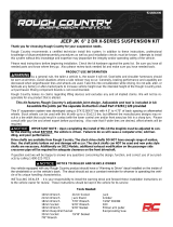
[DIAGRAM 1] Lower the axle enough
to facilitate installing the #02-5702 coil
spring spacers as shown. Remove
and discard the factory rubber
isolator. The spacer should be
installed on top of the coil spring with
the lip in the spacer pointing
downward.
Pry out the factory compression stop
from its mounting cup.
Press the #01-5702 compression stop
into the factory mounting cup.
3) FRONT RE-ASSEMBLY…
Raise the axle enough to seat the coil
springs against the spacers.
Re-attach the brake hose brackets to the frame using the factory hardware and tighten (250
in-lb).

FORM #5702.01-120506 PRINTED IN U.S.A. PAGE 3 OF 6
Bolt the anti-sway bar links to the differential using the factory hardware, followed by the
shocks. Tighten the anti-sway bar link hardware (80) and shock hardware (80).
NOTE: If the optional shock absorbers have been purchased, install them now.
4) TIRES / WHEELS…
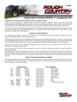
[DIAGRAM 2] Tighten the lug nuts (115) in the
sequence shown.
WARNING: When the tires / wheels are installed,
always check for and remove any corrosion, dirt, or
foreign material on the wheel mounting surface, or
anything that contacts the wheel mounting surface
(hub, rotor, etc.). Installing wheels without the proper
metal-to-metal contact at the wheel mounting
surfaces can cause the lug nuts to loosen and the
wheel to come off while the vehicle is in motion.
WARNING: Retighten lug nuts at 500 miles after any
wheel change, or anytime the lug nuts are loosened.
Failure to do so could cause wheels to come off while
vehicle is in motion.
5) PREPARE REAR OF VEHICLE…
Raise the rear of the vehicle with a jack and secure a jack stand beneath each frame rail,
just ahead of the trailing arms. Ease the frame down onto the stands, place transmission in
low gear or “park”, and chock front tires. Remove rear tires.
Unbolt the track bar at the frame. Save all hardware for re-use. Loosen, but do not remove,
the track bar bolt at the
differential.
6) REAR COIL SPRING
SPACERS…
Position a jack so that it
supports, but does not raise,
the rear axle.
Unbolt the lower end of the
shock absorbers at the axle,
followed by the anti-sway bar
links. Save all hardware for re-
use.
Unbolt the brake hose bracket
that secures the connection
between the metal line and
rubber hose. Save all
hardware for re-use.

FORM #5702.01-120506 PRINTED IN U.S.A. PAGE 4 OF 6
Loosen, but do not remove, the link arm bolts at both the axle and frame.
[DIAGRAM 3] Lower the axle enough to facilitate installing the #04-5702 coil spring spacers.
Remove and discard the factory rubber isolator. The spacer should be positioned on top
of the coil springs with the lip in the spacer pointing downward.
Pry out the factory compression stop from its mounting cup.
Press the #03-5702 compression stop into the factory mounting cup.
7) REAR RE-ASSEMBLY…
Raise the axle enough to seat the coil springs and spacers.
Re-attach the shock absorbers and anti-sway bar links at the axle using the factory
hardware. Tighten the shocks (80) and anti-sway bar links (80).
NOTE: If the optional shock absorbers have been purchased, install them now.
Re-attach the brake hose bracket to the frame using the factory hardware and tighten (250
in-lb).
Install the tires and wheels following the procedure in step 4.
8) CLEARANCE CHECK...
With the vehicle still on jack stands, and the suspension “hanging” at full extension travel,
cycle steering lock-to-lock and check all components for proper operation and clearances.
Pay special attention to the clearance between the tires / wheels and brake hoses, wiring,
etc.
Lower vehicle to the floor.
9) FINAL CLEARANCE and TORQUE CHECK...
Tighten the front and rear link arm bolts at both the axle (130) and frame (80).
Re-attach the front and rear track bars to the frame and tighten both ends of the bar (130).
With vehicle on floor, cycle steering lock-to-lock and inspect the tires / wheels, and the
steering, suspension, and brake systems for proper operation, tightness, and adequate
clearance.
Center the steering wheel using the adjustment found on the drag link.
Check the toe-in of the front axle. If it is out of adjustment, take the vehicle to be
professionally aligned.
10) Activate four wheel drive system and verify proper engagement.
11) HEADLIGHTS...
Readjust headlights to proper setting.

FORM #5702.01-120506 PRINTED IN U.S.A. PAGE 5 OF 6
12) SUPERLIFT WARNING DECAL...
Install the WARNING TO DRIVER decal on the inside of the windshield, or on the dash,
within driver’s view. Refer to the “NOTICE TO DEALER AND VEHICLE OWNER”
section below.
13) ALIGNMENT...
If necessary, align vehicle to factory specifications.
IMPORTANT PRODUCT USE INFORMATION
As a general rule, the taller a vehicle is, the easier it will roll over. Offset, as much as possible, what is lost
in roll over resistance by increasing tire track width. In other words, go “wide” as you go “tall”. Many
sportsmen remove their mud tires after winter / hunting season and install ones more appropriate for street
driving; always use as wide a tire and wheel combination as possible to enhance vehicle stability.
We strongly recommend, because of roll over possibility, that the vehicle be equipped with a functional roll
bar and cage system. Seat belts and shoulder harnesses should be worn at all times. Avoid situations
where a side rollover may occur.
Generally, braking performances and capabilities are decreased when significantly larger / heavier tires
and wheels are used. Take this into consideration while driving.
Do not add, alter, or fabricate any factory or aftermarket parts to increase vehicle height over the intended
height of the Superlift product purchased. Mixing component brands is not recommended.
Most states have some type of law limiting vehicle height. The amount of lift allowed, and how the lift may
be achieved, varies greatly. Several states offer exemptions for farm or commercially registered vehicles.
It is the owner’s responsibility to check state and local laws to ensure that their vehicle will be in
compliance.
Superlift makes no claims regarding lifting devices and excludes any and all implied claims. Superlift will
not be responsible for any altered product or any improper installation or use of our products.
We will be happy to answer any questions concerning the design, function, and correct use of our products.
IMPORTANT MAINTENANCE INFORMATION
It is the ultimate buyer’s responsibility to have all bolts / nuts checked for tightness after the first 100 miles
and then every 1000 miles. The steering, suspension and driveline systems, along with wheel alignment
should be inspected by a qualified professional mechanic at least every 3000 miles.
NOTICE TO DEALER AND VEHICLE OWNER
Any vehicle equipped with a Superlift lifting device must have the enclosed “Warning to Driver” decal
installed on the inside of the windshield or on the vehicle’s dash, within driver’s view. The “Warning to
Driver” decal is to act as a constant safety reminder for whoever may be operating the vehicle. The
WARRANTY IS VOID unless this decal is in place. INSTALLING DEALER... It is your responsibility to
install warning decal and forward these installation instructions to the vehicle owner for review of warnings,
product use and maintenance information. Replacement warning decals are available free upon request.
These instructions are to be kept with the vehicle registration papers and owners manual for the service life
of the vehicle.

FORM #5702.01-120506 PRINTED IN U.S.A. PAGE 6 OF 6
SUPERLIFT LIMITED LIFETIME WARRANTY
Suspension products bearing the Superlift (LKI Ent.) name are warranted for as long as the original
purchaser owns the vehicle that the LKI product was originally installed on. This warranty is non-
transferable. Warranty covers only the product, no labor, time loss, or freight incurred. Any product that
has been abused, altered, incorrectly installed, or used in competition is not covered. Product finish, spring
bushings, Polyurethane products, and normal wear is not covered. The LKI product is subject to
replacement or repair. No other warranties are expressed or implied. An authorized Superlift dealer must
inspect the part in question and confirm that the “Warning to Driver” decal is properly displayed. A copy of
the sales invoice is required for warranty consideration.
/