Page is loading ...

FORM#5709.01-062513 PRINTED IN U.S.A. PAGE 1 OF 13
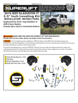
SUPERLIFT® 2.5” LIFT KIT FOR 2007-2014
JEEP WRANGLER (JK) 4WD AND 2WD
INSTALLATION INSTRUCTIONS
INTRODUCTION
Installation requires a professional mechanic. Prior to beginning, inspect the vehicles steering, drive-
line, and brake systems, paying close attention to the suspension link arms and bushings, stabilizer
bars and bushings, tie rod ends, pitman arm, ball joints and wheel bearings. Also check the steering
sector-to-frame and all suspension-to-frame attaching points for stress cracks. The overall vehicle
must be in excellent working condition; repair or replace all worn parts.
Read instructions several times before starting. Be sure you have all needed parts and know
where they install. Read each step completely as you go.
NOTES:
• Prior to beginning the installation, check all parts and hardware in the box with the parts list below.
Ifyoundapackagingerror,contactSuperlift®directly.Donotcontactthedealerwherethesys-
tem was originally purchased. You will need the control number from each box when calling; this
number is located at the bottom of the part number label and to the right of the bar code.
• A precision steering alignment, including the centering of the steering wheel, is required in or-
derforthevehicle’sElectronicStabilityProgramtofunctionproperly.Using“alllaser”alignment
equipment is recommended.
• For35”tires,Superlift’soptionalcompressiontraveldampenerkit(Part#5714)isrecommended
to prevent tire / fender scrub during extreme articulation.
• 2DoorWranglers-Duetoincreaseddriveshaftoperatinganglesandshortshaftlength,factory
reardriveshaftlifewillbereduced.Whenreplaced,Superliftsuggestsconvertingtoadualcardan
style shaft. These shafts can be purchased at many driveshaft shops.
• An arrow on diagrams indicates which direction is toward the front of the vehicle.
• Afoot-poundtorquereadingisgiveninparenthesis()aftereachappropriatefastener.
• Donotfabricateanycomponentstogainadditionalsuspensionheight.
• Prior to drilling or cutting, check behind the surface being worked on for any wires, lines, or hoses
thatcouldbedamaged.Afterdrilling,lesmoothanyburrsandsharpedges.
• Paint or undercoat all exposed metal surfaces.
• Prior to attaching components, be sure all mating surfaces are free of grit, grease, excessive un-
dercoating, etc.

FORM#5709.01-062513 PRINTED IN U.S.A. PAGE 2 OF 13
• A factory service manual should be on hand for reference.
• Usethecheck-offbox“”foundateachsteptohelpyoukeepyourplace.Two“”denotesthat
onecheck-offboxisforthedriversideandoneisforthepassengerside.Unlessotherwisenoted,
always start with the driver side.
IMPORTANT TIRE / WHEEL and CLEARANCE DATA
• Maximumtirewidthforuseonfactorywheelsis10.50”.FactoryWranglerwheelsare17”
diameterx7”widewith6.25”backspacing.Minimumaftermarketwheeldiameteris17”.
• Foran11.50”widetire,usean8”to8.5”widewheelwith3.25”to4.75backspacing.Ideal
backspacingis4.5”.--Fora12.50”widetire,usean8.5”to9”widewheelwith3.25”to4.75”
backspacing.Idealbackspacingis4.75”.With12.50”widetires,expectsomereartirescrub
at the plastic inner fender liners during full travel / articulation while off-roading; this generates
a slight sound, but no damage.
• Maximumtirediameteris35”.Foradequateclearanceof35”tiresduringfulltravel/
articulation while off-roading, minor body trimming is required at the front / lower corner of the
rear fenderwell openings. The rear ends of factory Rubicon rock rails must also be trimmed;
both trimming steps are detailed in these Instructions.
PARTS LIST … The part number is stamped into each part or printed on an adhesive label. Identify
each part and place the appropriate mounting hardware with it.
Step Part Number Qty. Decription Qty. New Attaching Hardware
Hardware
Bag
Number
701-580 2coil spring, front 2.5"
7 & 21 shock absorbers 4hydraulic shock
855-39-5704 1front lower brake hose bracket 11/2" Adel clamp 77-5709A
driver side 21/4" x 3/4" bolt
21/4" SAE washer
21/4" nyloc nut
855-40-5704 1front lower brake hose bracket 11/2" Adel clamp 77-5709A
passenger side 21/4" x 3/4" bolt
21/4" SAE washer
21/4" nyloc nut
955-01-5709 1sway bar link bracket 11/2" x 1-1/4" bolt 77-5709A
driver side 11/2" SAE washer
11/2" nyloc nut
955-02-5709 1sway bar link bracket 11/2" x 1-1/4" bolt 77-5709A
passenger side 11/2" SAE washer
11/2" nyloc nut
18 01-581 2coil spring, rear 2.5"
4 door model only
18 01-582 2coil spring, rear 2.5"
2 door model only
19 55-21-5704 1bracket, brake hose relocation, 11/4" X 3/4" bolt 77-5709A
driver side / rear 11/4" SAE washer
11/4" nyloc nut
11/4" x 1/2" self-tapping bolt
11/4" Adel clamp
20 55-22-5704 1bracket, brake hose relocation, 11/4" X 3/4" bolt 77-5709A
passenger side / rear 11/4" SAE washer
11/4" nyloc nut
11/4" x 1/2" self-tapping bolt
11/4" Adel clamp
29 55-03-5709 1alignment cam plates 477-5709B

FORM#5709.01-062513 PRINTED IN U.S.A. PAGE 3 OF 13
Kit Part Number 580 Kit Part Number 77-60424
Part Number Qty. Description Part Number Qty. Description
01-580 2coil spring, 2.5" front 01-60424 1straight wall poly bushing - 3/4"
Kit Part Number 581 Kit Part Number 77-5709A
Part Number Qty. Description Part Number Qty. Description
01-581 2coil spring, 2.5" rear 4 door 12ADC 21/2" Adel clamp
12C5NN 21/2" nyloc nut
Kit Part Number 582 12SW 21/2" SAE washer
12X114C5CS 21/2" x 1-1/4" bolt
Part Number Qty. Description 14ADC 21/4" Adel clamp
01-582 2coil spring, 2.5" rear 2 door 14C5NN 61/4" nyloc nut
14SW 61/4" SAE washer
Kit Part Number 5709 14X12STB 21/4" x 1/2" self-tapping bolt
14X34C5CS 61/4" x 3/4" bolt
Part Number Qty. Description
01-85290 2shock absorber, front Kit Part Number 77-5709B
01-85139 2shock absorber, rear
77-87033 1shock hardware bag Part Number Qty. Description
77-5709A 1hardware bag 55-03-5709 4alignment cam plates
77-5709B 1brake line bracket bag 55-21-5704 1brake line bracket, rear driver upper
55-22-5704 1brake line bracket, rear passenger upper
Kit Part Number 77-87033 55-39-5704 1brake line bracket, front driver lower
55-40-5704 1brake line bracket, front passenger lower
Part Number Qty. Description
01-60418 4hourglass poly bushing - 5/8"
24-5704 4sleeve - 0.75" x 0.5" x 1.535"
141991 2stem washer pack
01-60471 4stem bushing half - large
38F5N 23/8" fine thread nut
77-60424 4shock hardware bag
Drill StandardSockets 3/8"drive 3/8"
TorqueWrench 7/16"
Pry Bar 1/2"
Grinder 3/4"
File
Cut-OffWheel MetricWrenches 16mm
18mm
Ratchets 3/8"drive 21mm
1/2"drive
StandardWrenches 7/16"
Extensions 3/8"drive 12"long 9/16"
3/4"
Swivel 1/2"drive
DrillBits 7/32"
MetricSockets 3/8"drive 10mm 9/32"
15mm
16mm
1/2"drive 18mm
21mm
TOOLS REQUIRED:

FORM#5709.01-062513 PRINTED IN U.S.A. PAGE 4 OF 13
FRONT DISASSEMBLY
NOTE: Saveallfactorycomponentsandhardwareforreuse,unlessnoted.
1) PREPARE VEHICLE…
Placevehicleinneutral.Raisefrontofvehiclewithajackandsecureajackstandbeneath
each frame rail, behind the front / lower link arms. Ease the frame down onto the stands, place
transmissioninlowgearor“park”,andchockreartires.Removefronttires.
Positionajacksothatitsupports,butdoesnotraise,thefrontaxle.
2) TRACK BAR…
Removetheboltsecuringthefronttrackbar-to-axle.
3) STABILIZER BAR LINKS and SHOCK ABSORBERS…
Disconnectthefrontstabilizerbarlinksattheaxle.
Removeanddiscardtheshockabsorbers.
4) BRAKE HOSES, WIRING, and AXLE VENT HOSE…
Detachthefactorybrakehosebracket(oneperside)attheframe.Thisbracketholdsthe
connection between the rubber brake hose and the metal brake line.
NOTE: The following steps provide adequate wiring / vent hose length to accommodate additional
suspension extension travel:
Theupperendoftheaxleventhoseisclippedtotheleftsidecoiltower.Leavethehose
attachedtoframe;simplypulldownapproximately3”ofhose.
OnRubiconmodels,thewiringloomforthelockingdifferentialisattachedtotheaxle-to-frame
upper link. Remove and discard the clip.
4A) SOME 2010 and ALL 2011 and NEWER YEAR MODELS ONLY…
[Illustration1]Carefullyprythefactory
brake line bracket from the rubber hose. DO NOT DAM-
AGE THE HOSE IN THE PROCESS. If the hose is
damaged it MUST be replaced.
5) DRIVESHAFT…
Unboltthefrontdriveshaftatthefrontaxlethentieit
upandoutoftheway.Donotlettheshaft“hang”;this
risks pinching / damaging the grease boot at the trans-
fer case end.
6) AXLE LINK ARMS and COIL SPRINGS…
Loosen,butdonotremove,theupperandlower
link arm bolts at the axle and frame.
Illustration 1

FORM#5709.01-062513 PRINTED IN U.S.A. PAGE 5 OF 13
Lowertheaxleenoughtofacilitateremovingthefrontcoilsprings.Removethecoilsprings.
FRONT ASSEMBLY
7) COIL SPRINGS and SHOCK ABSORBERS…
NOTE:Performstep7onesideatatime.
Besurethefactoryrubberisolatorsarestillinplaceinsidetheuppercoil
tower.
Insertthecoilspringintotheuppertowerrst,followedbythelowerseat.Be
sure that the coils are indexed so they seat properly then raise the axle enough to
hold the coil springs in place.
[Illustration2]Installshockabsorber.Tightentheupperhardwareuntilbush-
ings swell slightly. Install the lower shock bolts, but do not tighten at this time. Ap-
plySuperliftdecals.Aftertheshockabsorberinstallationiscomplete,thejackcan
be lowered and relocated to allow installation on the opposite side.
8) BRAKE HOSES…
[Illustration3]Placethenewlowerbrakehosebracket(#55-39-5704left-hand
side;#55-40-5704right-handside)ontheaxleusingthesupplied1/4”x3/4”bolt,
washer,andNylocnut.(76in-lb)
Positiontheadelclamponthebrakehose,then
fastentheclamptothefrontofthenewSuperliftbracket
usingthesupplied1/4”x3/4”bolt,washer,andNyloc
nut. The steering must be cycled at this point to make
sure that there is enough slack in the brake hose when
the steering wheel is at full lock. If there is not adequate
hose at a full lock turn, loosen the Adel clamp bolt and
adjust the hose as needed.
AttachtheABSlinetotherearofthenewSuperlift
bracket using the factory clips. Reattach upper brake line
bracket.
9) STABILIZER BAR LINK BRACKET…
[Illustration4and5]Attachthestabilizerbarlink
bracket(#55-01-5709left-handside;#55-02-5709right-
handside)totheoutsideoftheoriginalstabilizerbarlink
axletabusingthesupplied1/2”x1-1/4”bolt,washer,and
Nylocnut(75).
Re-attachthefactorystabilizerbarlinktothenewSuperliftbracketreusingthefactoryhardware.
Illustration 2
Illustration 3

FORM#5709.01-062513 PRINTED IN U.S.A. PAGE 6 OF 13
(75)
10) FRONT DRIVESHAFT…
Connectthefrontdriveshaft-to-axleusingthefactory
hardware(81).
11) TIRES / WHEELS…
[Illustration6]Tightenthelugnuts(115)inthe
sequence shown.
WARNING: Whenthetires/wheelsareinstalled,
always check for and remove any corrosion, dirt, or
foreign material on the wheel mounting surface, or any-
thingthatcontactsthewheelmountingsurface(hub,
rotor,etc.).Installingwheelswithoutthepropermetal-
to-metal contact at the wheel mounting surfaces can
cause the lug nuts to loosen and the wheel to come off
while the vehicle is in motion.
WARNING: Retighten lug nuts at 500 miles after any
wheel change, or anytime the lug nuts are loosened.
Failure to do so could cause wheels to come off while
vehicle is in motion.
12) INITIAL CLEARANCE CHECK, FRONT…
Withthevehiclestillonjackstands,andthesus-
pension“hanging”atfullextensiontravel,cyclesteer-
ing lock-to-lock and check all components for proper
operation and clearances. Pay special attention to the
clearance between the tires / wheels and brake hoses,
wiring, driveshaft-to-crossmember, etc.
Lowervehicletotheoor.Finaltighteningandad-
justments to the front suspension installation will take
place once rear lift is completed.
REAR DISASSEMBLY
13) PREPARE VEHICLE…
Placevehicleinneutral.Raiserearofvehiclewithajackandsecure
a jack stand beneath each frame rail, just ahead of the rear / lower link
arms. Ease the frame down onto the stands, place transmission in low
gearor“park”,andchockfronttires.Removereartires.
Positionajacksothatitsupports,butdoesnotraise,therearaxle.
Illustration 4
Illustration 5
Illustration 6

FORM#5709.01-062513 PRINTED IN U.S.A. PAGE 7 OF 13
14) TRACK BAR and LINK ARMS…
Disconnectthefactorytrackbarfromtheaxleandloosentheframeattachmentpoint.
Loosen,donotremove,theboltssecuringbothlowerlinkarmstotheaxleandframe.
Loosen,donotremove,theboltssecuringbothupperlinkarmstotheaxleandframe.
15) BRAKE HOSES and WHEEL SPEED SENSOR WIRES…
Detachthefactorybrakehosebracketattheframe.Thisbracketholdstheconnectionbetween
the rubber brake hose and the metal brake line.
Locatedonboththeleftandrightsideupperlinkarmmounttherearetwoclipsthatretainthe
wheelspeedsensorwires.Disconnecttheforward-mostclipfromthearmmount.
16) STABILIZER BAR LINKS and SHOCK ABSORBERS…
Disconnecttherearstabilizerbarlinks.
Removeanddiscardthefactoryrearshockabsorbers.
17) COIL SPRINGS…
Lowertheaxlejustenoughtofacilitateremoving
the coil springs. The driveshaft has a rubber boot
on the transfer case end. If the axle is lowered too
much, boot bind / damage may occur.
REAR ASSEMBLY
18) COIL SPRINGS…
Installthenewcoilsprings.Rotatethecoilsso
that they seat properly in the coil buckets then raise
the axle enough to seat the springs.
19) STABILIZER BAR LINKS and SHOCK AB-
SORBERS…
Reconnectthestabilizerbarlinksusingthe
factoryhardware.Tighten(75).
Installshockswiththebodyoftheshockcylin-
deratthebottom,usingthefactoryhardware.Do
nottightenatthistime.ApplySuperliftdecals.
20) BRAKE HOSE and LINE RELOCATION,
LEFT-HAND SIDE…
[Illustration7]Aplasticframeclipattachesthe
metal brake line-to-frame; remove and discard this
clip.
Illustration 7
Illustration 8

FORM#5709.01-062513 PRINTED IN U.S.A. PAGE 8 OF 13
Attachtheleft-handsiderearbrakehoserelocationbracket(#55-21-5704)tothefactoryframe
location using the factory hardware. Be sure the bracket’s alignment tab engages with the hole in the
frame.Tighten(95in-lb).
Attachthebrakehose-to-bracketusingthesupplied1/4”x3/4”bolt,washerandNylocnut.Install
boltfromtheoutside,placethewasheronthenutsidethentighten(95in-lb).
[Illustration8]Carefullyre-formthemetallinesothatitrunsalongtheupperedgeoftheframe,as
shown...use extreme care, the line will kink / crimp easily. The supplied Adel clamp and self-tapping
boltwillcapturethefrontendofthemetalline.Measure1-3/8”downfromthetopoftheframerail,
and3-3/8”rearwardofthecompressiontraveldampenermount’scenterline.Atthispoint,drilla7/32”
pilot hole for the self-tapping screw.
CapturethemetallinewiththeAdelclamp
then attach clamp-to-frame using the self-tapping
screw.
NOTE: The goal is no line-to-frame contact at
anypoint;thispreventslinechangandpotential
brakefailure.Thoroughlyre-checkthenished
product for line-to-frame contact. This re-routing
also prevents potential line contact with the stabi-
lizer bar links during suspension articulation.
21) BRAKE HOSE and LINE RELOCATION,
RIGHT HAND SIDE...
[Illustration9]Carefullydetachthemetalbrake
line from the plastic frame clip. Now carefully pry
the frame clip from the frame; the clip will be relo-
cated and reused.
Attachtherearbrakehoserelocationbracket
(#55-22-5704)tothefactoryframelocationus-
ing the factory hardware. Be sure the bracket’s
alignment tab engages with the hole in the frame.
Tighten(95in-lb).
Attachthebrakehose-to-bracketusingthesup-
plied1/4”x3/4”bolt,washerandNylocnut.Install
bolt from the outside, place the washer on the nut
sidethentighten(95in-lb).
[Illustration10]Theplasticframeclip,removedinthepreviousstep,isrelocatedtobetweenthe
trackbarmountandcompressiontraveldampenermount.Measure1-3/8”downfromthetopofthe
framerailanddrilla1/8”pilotholethenenlargeto1/4”diameter.Nowplugtheplasticframeclipinto
the hole.
Carefullyre-formthemetallinesothatitiscapturedbytherelocatedframeclip...useextreme
care, the line will kink / crimp easily. Now continue to route the brake line forward, along the top of
Illustration 9
Illustration 10

FORM#5709.01-062513 PRINTED IN U.S.A. PAGE 9 OF 13
the frame, as shown.
ThesuppliedAdelclampandself-tappingscrewwillcapturethefrontendofthemetalline.Mea-
sure1-3/8”downfromthetopoftheframerailand3”forwardofthecompressiontraveldampener
mount’scenterline.Atthispoint,drilla7/32”pilotholefortheself-tappingscrew.
CapturethemetallinewiththeAdelclampthenattachclamp-to-frameusingtheself-tapping
screw.
NOTE:Thegoalisnoline-to-framecontactatanypoint;thispreventslinechangandpotential
brakefailure.Thoroughlyre-checkthenishedproductforline-to-framecontact.Thisre-routingalso
prevents potential line contact with the stabilizer bar links during suspension articulation.
FINAL PROCEDURES
22) TIRES / WHEELS and REAR TRACK BAR…
Installthetires/wheelsandtorquelugnutsasperstep15.
Reconnecttrackbarusingfactoryhardware.Thebarwillbetightenedinalaterstep.
23) INITIAL CLEARANCE CHECK, REAR…
Withthevehiclestillonjackstands,andthesuspension“hanging”atfullextensiontravel,check
all components for proper operation and clearances. Pay special attention to clearance between the
tires / wheels and brake hoses, driveshaft, etc.
24) HARDWARE TIGHTENING SEQUENCE…
Fronttrackbar,bothends(125).
Reartrackbar,bothends(125).
Rear/lowerlinkarmbolts-to-axle(125).
Rear/lowerlinkarmbolts-to-frame(125).
Rear/upperlinkarmbolts-to-axle(125).
Rear/upperlinkarmbolts-to-frame(125).
Front/lowerlinkarmbolts-to-axle(125).
Front/lowerlinkarmbolts-to-frame(125).
Front/upperlinkarmbolts-to-axle(75).
Front/upperlinkarmbolts-to-frame(75).
Allshockabsorbereyes(56).

FORM#5709.01-062513 PRINTED IN U.S.A. PAGE 10 OF 13
25) CENTER THE STEERING WHEEL…
NOTE: Thesteeringwheelmustbecenteredpriortodrivingthevehicle,oranElectronicStability
Program sensor may be activated resulting in a dash light and a warning chime that requires 20 plus
ignition key cycles to clear.
Startengineandturnthesteeringwheelsothattirespointstraightahead.Loosenthenutsonthe
drag link adjustment sleeve then rotate the sleeve until steering wheel center is achieved.
NOTE: [Illustration11]Inordertoachieveproperad-
justment sleeve clamping force, clamp / bolt assemblies
(foundonthedraglinkandtierodassemblies)mustbe
positioned as shown. The open side of each clamp must
align with the slot in the threaded adjustment sleeve.
Improper positioning and bolt torque will promote linkage
deection,whichmaycontributetotireshimmy.Tighten
clampbolts(26).Alsorelaythisinformationtothealign-
mentshopthatperformsthenalalignment.
26) FINAL CLEARANCE and TORQUE CHECK…
Cyclesteeringlock-to-lockandinspectthetires/
wheels, and the steering, suspension, and brake sys-
tems for proper operation, tightness, and adequate clearance.
27) HEADLIGHTS…
Adjustheadlightstopropersetting.
28) SUPERLIFT WARNING DECAL…
TheWARNINGTODRIVERdecalinstallsonthe
inside / top / center of the windshield frame, just below
the windshield frame’s tie-down loop. Prior to instal-
lation, pre-clean the surface with the supplied alcohol
cleaning pad.
29) ALIGNMENT…
Realignvehicletofactoryspecications.Aprecise
alignment, including the centering of the steering wheel,
isrequiredinorderforthevehicle’sElectronicStability
Program to function properly. A laser alignment is rec-
ommended.
Ifthevehiclerequiresanadjustmenttothecaster,
Superlifthasprovidedalignmentplatesthathavethree
positions; -1.5°, 0°, +1.5°.
[Illustration12]Onesideatatime,removetheboltsecuringthelowerlinkarm-to-axlethenre-
move the knock-outs that change the opening from a square hole to a slotted hole. A special tool is
available for this, or use a die grinder with a small cutting wheel. Install the alignment plates with the
boltholeinthedesiredposition.Snug-upthebolts.(125)
Illustration 11
Illustration 12

FORM#5709.01-062513 PRINTED IN U.S.A. PAGE 11 OF 13
30) TRIMMING REAR FENDERWELL OPENING...
[Illustration13]Foradequateclearanceofa35”tireduring
full travel / articulation while off-roading the front / lower corner
of the rear fenderwell opening will need to be trimmed on both
sidesofthevehicle.Measurefromthebottomedgeoftheweld
seamup3”andtothefront2”andmarkdiagonalcutline.
Oncethefenderismarked,usingtheappropriatecutting
tool, cut along the line and remove the triangle shaped piece
from the fender.
Aftercuttingcleantheeffectedareawithagrinderorle
and coat with paint.
31) TRIMMING FACTORY RUBICON ROCK RAILS...
NOTE: Disregardthisstepifvehicleisnotequippedwithfac-
tory Rubicon rock rails.
[Illustration14]Foradequateclearanceofa35”tireduring
full travel / articulation while off-roading the rear of the factory
Moparrockrailsneedtobetrimmedonbothsidesoftheve-
hicle.Measurefromthebackoftherockrailtothefront2”and
mark.
Oncetherailismarked,usingtheappropriate
cuttingtool,cutalongthelineandremovethe2”piece
from the rock rail. Remove the plastic end cap from
the cut piece.
Aftercuttingcleantheeffectedareawithagrinder
oraleandcoatwithpaint.Reinstalltheplasticend
cap in end of the rock rail.
Illustration 13
Illustration 14

FORM#5709.01-062513 PRINTED IN U.S.A. PAGE 12 OF 13
Superlift, LLC, Limited Lifetime Warranty
What is covered?Subjecttothetermsbelow,Superlift®willrepairorreplaceitsproductsfound
defective in materials or workmanship for so long as the original purchaser owns the vehicle on which
theproductwasoriginallyinstalled.YourwarrantorisSuperlift,LLC,doingbusinessasSuperlift®
SuspensionSystems(“Superlift®”).
What is not covered?YourSuperlift®LimitedWarrantydoesnotcoverproductsSuperlift®deter-
mines to have been damaged by or subjected to:
•Alteration,modicationorfailuretomaintain.
•Normalwearandtear(bushings,rodends,etc.).Scratchesordefectsinproductnishes(powder
coating,plating,etc.).
•Damageto,orresultingfrom,thevehicle’selectronicstabilitysystem,relatedcomponentsorother
vehicle systems.
•Racingorothervehiclecompetitionsorcontests.Accidents,impactbyrocks,trees,obstaclesor
other aspects of the environment.
•Theft,vandalismorotherintentionaldamage.
Remedy Limited to Repair or Replacement. The exclusive remedy provided hereunder shall, upon
Superlift’sinspectionandatSuperlift’soption,beeitherrepairorreplacementoftheproductcovered
underthisLimitedWarranty.CustomersrequestingwarrantyconsiderationshouldcontactSuperlift®
byphone(1-800-551-4955)toobtainaReturnedGoodsAuthorizationnumber.Allremoval,shipping
and installation costs are customer’s responsibility.
IfareplacementpartisneededbeforetheSuperlift®partinquestioncanbereturned,youmustrst
purchase the replacement part. Then, if the part in question is deemed warrantable, you will be cred-
ited / refunded.
Other Limitations - Exclusion of Damages - Your Rights Under State Law
•NeitherSuperlift®noryourindependentSuperlift®dealerareresponsibleforanytimeloss,rental
costs, or for any incidental, consequential or other damages you may have.
•ThisLimitedWarrantygivesyouspecicrights,andthisistheonlywarrantySuperlift®makesin
connection with your product purchase. You may also have other rights that vary from state to state.
For example, while all implied warranties are disclaimed herein, any implied warranty required by law
islimitedtothetermsofourLimitedLifetimeWarrantyasdescribedabove.Somestatesdonotallow
limitations of how long an implied warranty lasts and / or do not allow the exclusion or limitation of
incidental or consequential damages, so the limitations and exclusions herein may not apply to you.
Superlift®neitherassumesnorauthorizesanyretailerorotherpersonorentitytoassumeforitany
otherobligationorliabilityinconnectionwiththisproductorLimitedWarranty.

FORM#5709.01-062513 PRINTED IN U.S.A. PAGE 13 OF 13
SUPERLIFT SUSPENSION
300 Huey Lenard Loop Rd.
West Monroe, Louisiana 71292
Phone: (318) 397-3000
Sales / Tech: (800) 551-4955
Fax: (318) 397-3040
www.superlift.com
Superlift, LLC, Satisfaction Guarantee
Wewantyoutopurchaseourproductwithcondenceandbe100%satisedwiththeendresult.If
youhaveanylegitimateissue,andSuperlift®cannotrectifyittoyoursatisfaction,Superlift®willtake
backtheSuperlift®brandproductandrefundthecustomer100%oftheproductpurchaseprice.
The details:
•Offervalidtotheoriginalretailconsumerforsixmonthsafterproductpurchase.
•MayrequireaSuperlift®dealer’sparticipationinordertoassistin“troubleshooting”theissue.
•Anycostsrelatedtolabor,freight,incidentalorconsequentialarenotrefunded.
•RefundwillnotexceedSuperlift’s®publishedretailprice.
Important Product Use and Safety Information / Warnings
As a general rule, the taller a vehicle is, the easier it will roll over. Offset, as much as possible, what
islostinrolloverresistancebyincreasingtiretrackwidth.Inotherwords,go“wide”asyougo“tall”;
alwaysuseaswideatireandwheelcombinationasfeasibletoenhancevehiclestability.Westrongly
recommend, because of rollover possibility, that the vehicle be equipped with a functional roll bar and
cagesystem.Seatbeltsandshoulderharnessesshouldbewornatalltimes.Avoidsituationswhere
a side rollover may occur.
Generally,brakingperformanceandcapabilitiesaredecreasedwhensignicantlylarger/heaviertires
and wheels are used. Take this into consideration while driving. Also, changing axle gear ratios or
using tires that are taller or shorter than factory height will cause an erroneous speedometer reading.
On vehicles equipped with an electronic speedometer, the speed signal impacts other important func-
tionsaswell.Speedometerrecalibrationforbothmechanicalandelectronictypesishighlyrecom-
mended.
Donotadd,alter,orfabricateanyfactoryoraftermarketpartstoincreasevehicleheightoverthein-
tendedheightoftheSuperlift®productpurchased.Mixingcomponentbrandsisnotrecommended.
/