CAME Z Series Owner's manual

Type
Owner's manual

This manual is also suitable for

AUTOMAZIONE PER CHIUSURA INDUSTRIALE
CONTROL PANEL FOR 400V GEARMOTORS
ZA2S
INSTALLATION MANUAL
Z SERIES
2
The data and information reported in this installation manual are susceptible to change at any time and without obligation on CAME cancelli automatici s.p.a. to notify users.
ENGLISH
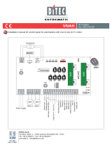
- Make sure the distances and cable diameters are as shown in the table at chapter 5.4.
- The overall power of the motors must not exceed 1200W.
4 Description
The ZA2S control panel has been engineered to control the SUPERFROG automations, to operate swing doors.
The use of this product for purposes other than as described above and installation executed in a manner other than
a
s
in
s
t
r
u
c
ted in this technical manual are prohibited.
2.2 Limits to use
The control panel is powered by 230/400V a.c. triphase through the R-S-T-N terminals, with 50/60Hz frequency.
The command devices and accessories run on 24V. Moreover, the total accessories cannot run on more than 40W.
A 12V electric-lock can connected to the system.
The control panel automatically controls the following functions:
1) automatic closing (adjustable);
2) working cycle (adjustable);
3) open-close or only opening command;
4
) Reopenin
g during the closing phase, re-closing during the opening phase or partial stop;
5) Maintained action (on the card, cut the spot marked with the symbol);
6) pre-flashing upon opening and closing;
7) obstruction detection when motor is not running;
8) Delaying the opening of the 1st gate leaf and during closing of the 2nd leaf (the latter is adjustable).
4.1 Technical specifications
Power Supply: 230/400V A.C. 50/60Hz tri-phase
Power draw when idle: 100mA
Max Power for accessories 12V: 15W
Max Power for accessories 24V: 30W
Max Power for accessories 230V: 30W
#
#
Protection level: IP54
Weight: 6.2 kg
Insulation class:
Material: ABS
FUSE
Protection Fuse type
Low-tension 2A
1 Legend
This symbol indicates sections to be read with particular care.
This symbol indicates sections concernig safety.
This symbol indicates notes to communicate to users.
2 Destination and limits of use
“IMPORTANT SAFETY INSTRUCTIONS FOR INSTALLATION”
“CAUTION: IMPROPER INSTALLATION MAY CAUSE SERIOUS DAMAGE, FOLLOW ALL INSTALLATION INSTRUCTIONS CAREFULLY”
“THIS MANUAL IS ONLY FOR PROFESSIONAL INSTALLERS OR QUALIFIED PERSONS”
2.1 Intended use
This product complies with the following standards: EN 12978, UNI EN 954-1, CEI EN 60335-1, UNI EN 12453.
3 Reference standards
3
The data and information reported in this installation manual are susceptible to change at any time and without obligation on CAME cancelli automatici s.p.a. to notify users.
ENGLISH
4.2 Dimensions, distance between centres and fixing holes
MM
MM
MM
MM
MM
4.3 Main components
1) Main switch
2) Cut-off switch
3) Power meter
4) Safety switch for 1st motor
5) Safety switch for 2nd motor
6) 400-24V Transformer
7) Terminal for connecting to power source
8) Terminal for connecting gearmotors and
flashing lamp.
9) Opening remote control switch for 1st motor
10) Closing remote control switch for 1st motor
11) Opening remote control switch for 2nd motor
12) Closing remote control switch for 2nd motor
13) Low voltage fuse
14)TR2M Trimmer: to adjust the delayed closing
of the 2nd motor
15) TL Trimmer: to adjust the working time
16) TCA Trimmer: to adjust the automatic closing
17) Function selector
18) Terminal to connect accessories and com-
mand devices
Warning! Before doing any work on the auto-
mation kit, c
ut off the pwer supplì and disconnect
the emergency batteries (if connected).
/03%.3
/.
/03%.3
/03%.3
2
34
.
57 6 8 79
%
%
1
14
2 3 4 5
7
9
10
11 12
6
15
17
16
13
18
8
4
The data and information reported in this installation manual are susceptible to change at any time and without obligation on CAME cancelli automatici s.p.a. to notify users.
ENGLISH
Before proceeding with the installation, it is necessary to:
Make sure that the control panel is attached in a protected and impact-free area, that the surface it is attached is solid, and that
it is attached to the surface with proper tools (screws, anchor lugs, and so on);
• Provide for a suitable omnipolar disconnection device with contacts more than 3 mm apart, and independent (sectioned off)
power supply;
Make sure that any connections inside the container (made for the continuity of the protection system) are provided with
additional insulation compared to the other conductive parts inside;
• Make sure that any connections inside the case (that provide continuance to the protective circuit) be fitted with extra insula-
tion as compared to the other conductive parts inside.
Attach the base of the control panel in a protected area, we
suggest using round head screws with 6 mm diameter with
a Phillips drive head.
5.3 Attaching the control panel
Puncture the pre-drilled holes and insert the cable glands with
conduits for the electric wires.
Note: the predrilled holes have different diameters, these being
23, 28 and 37 mm.
After making the necessary adjustments, fix the cover using the
screws supplied.
5 Installation
5.1 Preliminary checks
Make sure all tools and materials necessary are within reach to install the edge in total safety, and in compliance with the
regulations in force. The following figure illustrates the minimum equipment needed by the installer.
5.2 Tools and materials
5
The data and information reported in this installation manual are susceptible to change at any time and without obligation on CAME cancelli automatici s.p.a. to notify users.
ENGLISH
2
34
.
57 6 8 79
%
%
Connection for the delayed opening 230/400V A.C. 50/60Hz tri-phase gearmotor
M
57 6 8 79
%
%
M
Connection for the delayed closing 230/400V A.C. 50/60Hz tri-phase gearmotor
57 6 8 79
%
%
Connections Type of cable Length of cable 1 < 10 m L. of cable 10 < 20 m L. of cable 20 < 30 m
230/400V 3F power supply
FROR CEI
20-22
CEI EN
50267-2-1
4G x 1,5 mm
2
4G x 2,5 mm
2
4G x 4 mm
2
230/400V 3F motor power supply 4G x 1 mm
2
4G x 1,5 mm
2
4G x 2,5 mm
2
Flashing lamp 2 x 0,5 mm
2
2 x 1 mm
2
2 x 1,5 mm
2
Photocell transmitters 2 x 0,5 mm
2
2 x 0.5 mm
2
2 x 0,5 mm
2
Photocell receivers 4 x 0,5 mm
2
4 x 0,5 mm
2
4 x 0,5 mm
2
power supply to accessories 2 x 0,5 mm
2
2 x 0,5 mm
2
2 x 1 mm
2
Control and safety devices 2 x 0,5 mm
2
2 x 0,5 mm
2
2 x 0,5 mm
2
Antenna connection RG58 max. 10 m
5.4 Cable list and minimum thickness
N.B.: if the cable length differs from that specified in the table, then you must determine the proper cable diameter in the basis of
the actual power draw by the connected devices and depending on the standards specified in CEI EN 60204-1.
For connections that require several, sequential loads, the sizes given on the table must be re-evaluated based on actual power
draw and distances.
When connecting products other than those mentioned in this manual please see the documents provided with the products
themselves.
5.5 Electrical connections
Power Supply 230/400V A.C. 50/60Hz tri-phase
Movement Flasher (contact capacity: 230V – 25W max.)
Flashes during the opening and closing phases.
6
The data and information reported in this installation manual are susceptible to change at any time and without obligation on CAME cancelli automatici s.p.a. to notify users.
ENGLISH
24V A.C. output for powering accessories 30W max.
Closing button (N.O. contact) – Gate closing button
Opening Button (N.O. contact) – Gate opening button
24V – 3W max. Flashing lamp. – Lamp signalling that gate is open.
Stop button (N.C. contact) - Stops movement, excludes the automatic closing functions.
To restart the automated kit, press a command button or a remote control button.
Push button controlled (N.O. contact) - Opening and closing devices.
Command modes: open-close
Key selector (N.O. contact) - Opening and closing devices.
Command modes: open-close
#
#
#
#
#
#
#
7
The data and information reported in this installation manual are susceptible to change at any time and without obligation on CAME cancelli automatici s.p.a. to notify users.
ENGLISH
(N.O.) Contact output with two-channel receiver
Contact rate (with resistive load): 1A – 24V D.C.
(N.O.) contact output – the contact shuts off for 3” with
each opening-impulse.
Contact rate: 2A – 230V A.C.
Connection for the 12V electric-lock – 15W max.
(N.C.) Contact for “partial stop” – Input for photocells, sensitive edges and
other devices complying with the EN 12978 standard. Stops the gate leaf if it
is moving and, if set up, automatically closes the gate.
If this contact is not used bridge the terminals amongst themselves.
(N.C.) Contact for “re-closing during opening” – Input for photocells, sensiti-
ve edges and other devices compliant with EN 12978 standards.
During opening, operation of the device causes inversion of direction until
complete closure is obtained.
If this contact is not used, bridge the terminals amongst themselves.
(N.C. Contact for “re-opening during closing” - Input for photocells, sensiti-
ve profi les and other devices complying with EN 12978 standards.
During the closing phase, operating the device will invert the motion until
complete opening is achieved.
If this contact is not used, bridge the terminals amongst themselves.
#
# # " " 3 " "
#
# # " " 3 " "
# # " " 3 " "
#
# # " " 3 " "
#
# # " " 3 " "
8
The data and information reported in this installation manual are susceptible to change at any time and without obligation on CAME cancelli automatici s.p.a. to notify users.
ENGLISH
5.7 Adjustments
5.6 Function selection
/.
ON
OFF
/03%.3
/.
/03%.3
/03%.3
/03%.3
/.
/03%.3
/03%.3
42-
4,
4#!
Trimmer TL. = regulates the motor working time, for each single opening or closing, it has a range of 2 to 60 seconds
Trimmer T.C.A. = Adjusts the waiting time in the opening position. Once this time frame has lapsed, an automatic closing pro-
cedure is performed. The waiting time may be adjusted to between 3 second and 60 seconds. Adjusting to the minimum excludes
the automatic closing function.
Trimmer T.R.2M. = Adjusts the waiting time closure delay for 2nd motor (3 to 10 seconds)
1 ON - Pre-fl ashing upon opening and closing – Following an opening or closing command, the fl ashing light connected on
E1-E2, fl ashes for 5 seconds before the cycle begins.
2 ON - Automatic closing – the timer for the automatic closing is activated when the door completes its opening cycle. The set
time is adjustable, and it is any how conditioned by the possible intervention of the safety devices and dies not activate
after a total safety ‘stop’ or during a power outage.
N.B.: If «maintained action» mode is selected, check that the automatic closure function is disactivated (2 OFF).
3 ON - Detection of obstacle – When motor is not running (gate closed, open or after a total stop command), prevents any
movement if the safety devices (e.g. the photocells) detect an obstacle
4ON / 5OFF - open only’ function with radio transmitter (with radio frequency card inserted).
5ON/ 4OFF - ‘open-close-inversion’ function with button (2-7) and radio transmitter (with radio frequency card inserted).
9
The data and information reported in this installation manual are susceptible to change at any time and without obligation on CAME cancelli automatici s.p.a. to notify users.
ENGLISH
6 Demolition and disposal
We use different materias to manufacture our products. Most of them (aluminium, plastic, iron, electric cables) is dispo-
sable urban waste. They may be recycled through special collection and disposal at licensed centres.
Other components (electronic cards, batteries for the remote controls, etc.) may contain polluting materials. They must
therefore be removed and given to licensed companies that specialise in collecting and disposing of such materials.
MANUFACTURER’S DECLARATION OF CONFORMITY
Pursuant to annex II B of the Machinery Directive 98/37/EC
CAME Cancelli Automatici S.p.A.
via Martiri della Libertà, 15
31030 Dosson di Casier - Treviso - ITALY
tel (+39) 0422 4940 - fax (+39) 0422 4941
internet: www.came.it - e-mail: [email protected]
Declares under its own responsibility that the equipments for automatic garage doors and
gates listed below:
… comply with the National Law related to the following European Directives and to the
applicable parts of the following Standards.
98/37/CE - 98/79/CE M
ACHINERY DIRECTIVE
98/336/CEE - 92/31/CEE E
LECTROMAGNETIC COMPATIBILITY DIRECTIVE
73/23/CEE - 93/68/CE LOW VOLTAGE DIRECTIVE
89/106/CEE CONSTRUCTION PRODUCTS DIRECTIVE
EN 13241-1 EN 12635 EN 61000-6-2
EN 12453 EN 12978 EN 61000-6-3
EN 12445 EN 60335-1 EN 60204-1
IMPORTANT WARNING!
Do not use the equipment specifi ed here above, before completing the full installation
In full compliance with the Machinery Directive 98/37/EC
7 Manufacturer’s warranty
Reference code to request a true copy of the original: DDF B EN A003 ver.1.0
CONTROL PANEL FOR ZA2S SWING GATES
Cod. 319U04 ver. 0.1 07/06 © CAME CANCELLI AUTOMATICI
CAME UNITED KINGDOM LTD
UNIT 3, ORCHARD BUSINESS PARK TOWN
STREET, SANDIACRE
NOTTINGHAM - NG10 5BP - U.K.
Tel 0044 115 9210430
Fax 0044 115 9210431
  • Page 1 1
  • Page 2 2
  • Page 3 3
  • Page 4 4
  • Page 5 5
  • Page 6 6
  • Page 7 7
  • Page 8 8
  • Page 9 9
  • Page 10 10

CAME Z Series Owner's manual

Type
Owner's manual
This manual is also suitable for

Ask a question and I''ll find the answer in the document

Finding information in a document is now easier with AI