Page is loading ...

AUTOMATIC ENTRANCE SPECIALISTS
CE
EL12E IP1892
rev. 2008-06-03
+
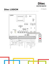
Battery 12V 2 Ah - F10A
Manuale di installazione quadro elellronico per automazione WELE.
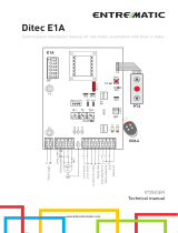
Electronic control panel installation manual for WELE automations.
Notice d'installation de la carte electronique pour automatisme WELE.
Installationsanleitung fOrSteuerung WELE.
Manual de instalaci6n cuadro electr6nico para automaci6n WELE.
Manual de instalac;;ao do quadro electr6nico para a automac;;ao WELE.
n
Velocita di
chi usura /
Closing speed
06
m~~
Bassa
fLow
5D~
Media / Medium
3:D~
m~;;
AlIa/High
m "
;:;Dm
c
m~~
Uscita serratura
r-D
I~
Lock output
24 V=
I
max
1,2 A
+
~O
m~d
Vseita /
Output
24 V= I 0.5 A ;
cD
m~C5
~O
....0
0
Chiusura automatica /
Automatic closure
---
NO
Z
Apertura /
Opening
---
"'0
~;g
Sicurezza in apertura /
Opening safety
enD
Sicurezza d'inversione / Safety reversal
"'0
F2=F6,3A
I~I
BlulBlue
Nero/Black
Verde/Green~
Grigio/Grey---~
Nero/Black--
BianCOIWh;re~
BlulBlue
---.J
• Battery 12V 2 Ah +
DO 2l
DD~
~
Fusibile di linea
Line fuse
F1 = F1,6A
A1imentazione
r0
Power supply -
z
ICJ
230 V-ISO Hz 'ii-
0
All
MIN MAX
TA
Durata comando apre
Os 25 s
Duration of opening command
TC
Tempo sosta apre
Os 25 s
Open break time
VA
Velocita
apre
10 s/90' 2 s/90'
Opening speed
VC
Velocita chiude
8
s/90' 3 s/90'
OFF ON
Closing speed
PG
Apertura a spinta Push&Go Disabilitato Abilitato
RA
Rallentamento apre
Push&Go opening Disabled
Enabled
Slow-down opening speed
lelM
1509001
Cart. n° 0957
DITEC S.pA
Via Mons. Banfi, 3 • 21042 Caronno Perlusella filA). ITALY
Tel. +3902963911 • Fax +39 02 9650314

GENERAL SAFETY PRECAUTIONS
@
1.\
This installation manual is intended for professionally competent personnel only. Installation, electrical connections and
ill
adjustments must be performed in accordance with Good Working Methods and in compliance with applicable regulations.
Before installing the product, carefully read the instructions. Bad installation could be hazardous. Before installing the product,
make sure it is in perfect condition. For repairs or replacements of products only original spare parts must be used.
1.
TECHNICAL DATA
Refer to technical data and CE declaration of conformity contained in the manuals for WEL automations.
2. ELECTRICAL CONNECTIONS
Warning: link up ail N.C. contacts lif not used) by means of jumpers. The terminal bearing the same number are equivalent.
2.1 Controls
Control Function Description
1 ____ 2
N.O. AUTOMATIC CLOSING Automatic closing can be enabled by a permanent contact or it can be
managed by means of COMH-K function selectors.
1 ____ 3
N.O. OPENING Start the opening operation. The duration of the open command is re-
gulated by the TA trimmer.
1~6 N.C. OPENING SAFETY The opening operation that is being performed is abruptly slowed until
the complete stop without interrupting the count of the stop time and
automatic closing.
1~8 N.C. REVERSAL SAFETY CONTACT Reverses movement (re-opens) during closing.
FA~ N.C. OPENING LIMIT SWITCH
Deceleration during opening.
FC ___ N.O. CLOSING LIMIT SWITCH Deceleration during closing.
2.2 Output and accessories
Output Value Description
1
~
+24 V=
1
05 A (max) Accessories power supply. Output for powering of external accessories.
0
~
.
• LK + 24 V=
11,2
A (max) Electric lock (impulsed output). The electric lock is powered for 1 second
12V-/1SW
each time an opening command is received when the automation is closed or
during the closing operation.
• MOT + Motor connection .
POWER AL 1 power supply device connection.
BAT 2x12V 12Ah Battery kit. WELBAT battery kit connection enables operation in continuity
mode also in the event of power failure.
The electronic control panel connects the battery oniy if power supply is pre-
sent and keeps
it
charged;
it
uses
it
as a buffer battery or in the event of power
failure and disconnects it when voltage drops under 22 V after 30 s. To charge
battery, connect mains and battery kit at least 30 min. before starting up the
system. To stop powering the electronic panel, turn off power supply and di-
sconnect battery.
Warning: to ailow recharge, battery kit must be always connected to electric
control. Regularly check for battery kit efficiency.
7
EL 12E - IP1S92

DESCRIPTION MIN. MAX.
TA Duration of the opening command. Adjusts the duration of contact 1 - 3 continua- Os 25 s
tion.
TC Stop time during opening. Stop time adjustment during opening. The count starts Os 25 s
after the FAis activated and when the time set with the TAhas elapsed.
VA Opening speed. Adjust the opening speed. 10s/90" 2 s/90"
CLOSING SPEeD 20 'Is 60 'Is
IOJ2p
o
l
Low closing speed selection contact;
4.5 sl90" 1.5s/90"
or
CLOSING SPEED
I?O?OI
medium closing speed selection contact;
ME or
CLOSING SPEED
IpOD~!
high closing speed seiectlon contact.
'"'"
B
It adjusts closing speed only when high closing speed is selected.
VC
RA Slow-down opening speed. Adjust the opening speed after the tripping of limit switch //
FA.
@2.3 Trimmer
2.4 Dip-Switches
Description
PG Push&Go manual opening
2.5 Signals
Disabled OFF Enabled ONu
LED Flashing
/
3.
DOORS REQUIREMENTS FOR HANDICAPPED PEOPLE USE
Ifthe WELE is used on doors for use also by handicapped persons. adjust the VA(opening) and VC (closing) so that the opening
and closing times (excluding slow-down) are the same as or greater than those indicated in the following table.
Door wing weight
Door wing length 50 kg 60 kg 70 kg 80 kg 90 kg
750 mm 35 3.1s 3.2 5 3.3 s 3.5 s
850 mm 3.1s 3.15 3.2 s 3.4 5 3.6 5
1000 mm 3.25 3.4 5 3.7 s 45 4.25
1200 mm 3.8 s 4.25 4.5 5 4.85 5.1s
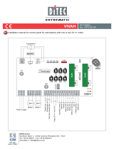
Perform also the adjustments indicated in figure:
CLOSING
"'. VC adjustment
\
~>1.5S
5b<l1" , ~
~ ~
g
Attendere
I Wait for
<!:
5 s
~~
!!.~ '
VA adjustment
OPENING
EL 12E - IP1892
8

4.
STARTUP
@
1.\
ATTENTION: Before performing any procedure. make sure that the device is not powered and that the batteries are dis-
ill
connected.
The operations regarding point 4.3 are without safety devices. The trimmer can only be adjusted with door not moving.
4.1 Adjust all trimmers to 1/4 rotation.
4.2 Short circuit the safety devices (1-6. 1-8) and the stop (1-2).
4.3 Power and by means of controls 1-3 and 1-4 check that the automation is working properly.
Adjust the opening speed with the VA trimmer.
Adjust the RA trimmer and move the opening limit switch FA to obtain a correct deceleration.
Adjust the door open stop time with the TC trimmer.
Adjust the desired spring closing speed by means of the CLOSING SPEED LO-ME-HI jumper and VC trimmer.
Move the FC closing limit switch to obtain a correct deceleration.
4.4 Make an estimate of the risks present and install and connect all the necessary safety devices (1-6, 1-8) to the electronic
control panel. Check for their efficiency.
4.5 If push opening is required set PG=ON.
4.6 Connect any control devices and function selectors. Check for their efficiency.
..
_
..
--
---
-
.
,
....
Problem Possible causes Remedy
The door does not open or clo- COMH.K function selector with wrong setting. Check and adjust COMH.K function selector set-
se or else it does not carry out tings.
set functions.
Defective wirina. Replace the wiring.
COMH-K function selector not working. Replace COMH-K function selector.
The door does not open or clo-
Power failure.
Make sure electric control panel is powered.
se.
Accessories short circuit.
Disconnect accessories from terminals 0-1 (with
24 V DC voltage) and connect them again one
at a time.
Burnt line fuse. Replace line fuse.
Safety devices are triggered. Check terminals 6 and 8 of the electronic control
panel.
Make sure photocells and safety devices are
clean and efficient.
Radars are not triggered. Make sure radars are working properlv.
The door is blocked by bolts and locks. Make sure the wing can move freely.
The door opens but does not Radars are triggered. Make sure the radar is not subject to vibrations,
close.
nor carrying out false detections or detecting mo-
ving objects within its range of action.
Automatic closing does not work. Check 1.2 jumper and (if present) function se-
lector position. Check the activation of the FA limit
switch and adiustment of the TA trimmer.
External safeties are not trigge- Wrong connections between safety devices Connect in series N.C. safety contacts and remo.
red. and electronic control panel. ve any jumper.
The door opens by itself. The radars are unstable or detect
moving
Make sure the radar is not subject to vibrations,
objects. nor carrying out false detections or detecting mo-
ving obiects within its ranQe of action.
The door opens/closes for a Inverted motor wires. Check motor wires.
short interval than stops. Some friction is present. Check manually that the wing can move freely.
Make sure there is no dirt or orit under the wing.
5.
TROUBLESHOOTING
EL 12E -IP1892

@6.
6.1
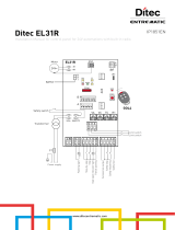
EXAMPLE OF APPLICATION
Automations in parallel
OUTSIDE INSIDE
REM REM
OUTSIDE OUTSIDE
,
:1
'0',;
0
0"
o (,
~-FCWEL2
I>
JJ(
WEL2 WEL1
If the door has two overlapping leaves, two auto-
mations can be controlled in parallel [WEL 1] and
[WEL 2), using the connections indicated in the
drawings.
The movement of the two leaves is not synchro-
nised, the first leaf [WEL1] only closes when the
second leaf [WEL2] is completely closed.
The opening speed trimmer (VA) must be adjusted
in the same position in both automations.
The TC trimmer for the automation that closes the
first leaf [WEL 1) should be adjusted to minimum.
For automatic closing of the firstleaf[WEL1], a limit
switch must be installed that will be activated when
the second leaf [WEL2] is closed. Connect the limit
switch as shown in the diagram.
Note: the closure limit switch [FC WEL2] is not
supplied by us with automations and must be ap-
plied to the leaf.
REM PAS PAS
r'1
24v
,....-,
24V
,....-,
24V
+
-
+
.
+
.
"
m~~ WEL2
O~
~ @
oD~
m~
~D~
:rom
m~~
0
If-°1
:;:0
m~rJ
.
~
m~C1
•
-0
~O
0
-
"'0
z
.-
-,
v.>lCJ
I .-=:JI~
mO
F2=FB,3A
~O
.
~
I~I
"'0
»0
-05
m~~ WELl
coD
-
[
5D~
(OD
~Cl~
m~
~Cl
m ~
~D
~~
m~~
~Cl
rrn
COMH
~CJ
m~TC = MIN
COMK
r;;o
m~C1
~D
I I
-0
~
'---
"'0
[uJ~
L...,J +
.
~O
24V
0),0
F2=FB,3A
REM
~
I~I
FCWEL2
OUTSIDE INSIDE
REM REM
OUTSIDE OUTSIDE
9
',I
f
WEL2
[5
WEL1
In case of a swing door with two doors without
overlap, it is possible to control 2 automations
[WEL 1J and [WEL 2] concurrently, making sure
that the connections, as indicated in the figures,
have the following variants:
set the VA, VC, TC trimmers in the same posi-
tions.
do not install the limit switch FCWEL2.
The movement of the two doors is not synchroni-
sed.
EL12E .IP1892
REM PAS PAS
r'1 24V
,....-,
24V
,....-,
24V
+
.
+
-
+
-
"
ml~ WEL2
Cl5
~
~
oOil\
m~
3:0(1)
~Oi!i
ml~
If-
01
':"0
mlrJ
•
00
mlC1
-0
-0
~
-
"'0
~~
.
~O
mO
F2=FB,3A
-0
coD
I~I
"'0
•
»0
----0
g
ml~ WELl
coD
-
[
51D~
<DO
'"
m~
~D
~C1~
~D
~m ml~
lllO
If-
01
COMH
':"0
m~rJ
COMK
=;;0
ml~
I'
~O
-0
0
-
"'0
z
L...,J +
.
wD
~~
24v
enD
F2=F6,3A
REM
coD
I~I
10

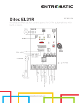
6.2 Door with Push&Go opening, articulated arm (WELBA) and control for disabled people.
tG8'
The door opens by PAS radar control (1-3) and PUP push-button (1-3), closes automatically (1-2), operates opening safety by ~
means of REM device (1-6).
Manual pushing (or pulling) of the door triggers motorized opening (PG=ON).
r--
REM
PAS PAS PUP
rl
24V
r1
24 V
r1
24V
r1
+
-
+
-
+
-
-
'"
m);;
D
@
5D
z
m)fi
~O
'"
w
~
:CD
m
m)~
m
'"
rn
~D
m)ri
00
m)(;
~
......D
,-
-0
0
"'0
z
•
i
"'0
~G'S
I
mO
LF2=F6,3A
"'0
1t==}1
~
PUP
INSIDE OUTSIDE
INSIDE INSIDE
All rights reserved
All data and specifications have been drawn up and checked with the greatest care. The manufacturer cannot however take any
responsibility for eventual errors, omissions or incomplete data due to technical or illustrative purposes.
11
Fl1?F.IP1RQ?
/