Page is loading ...

Instructions
This publication will guide you through installation of an IP 20
(NEMA Type 1) Enclosure Kit (1336S/F/T-AAx) or EMC Enclosure
Kit (1336S/F/T-AEx). Refer to the appropriate drive User Manual for
further information.
Enclosure Installation
!
ATTENTION:ThisdrivecontainsESD(Electrostatic Dis-
charge) sensitive parts and assemblies. Static control pre-
cautions are required when installing, testing, servicing or
repairing this assembly. Component damage may result if
ESD control procedures are not followed. If you are not
familiar with static control procedures, reference A-B pub-
lication 8000-4.5.2, “Guarding Against Electrostatic Dam-
age” or any other applicable ESD protection handbook.
!
ATTENTION: To avoid a shock hazard, assure that all
powertothedrivehasbeenremovedbeforeproceedingwith
thefollowing procedure. In addition, verifythat the DC bus
hasdischargedbymeasuring across the “+DC”and “–DC”
terminals of TB1 with a voltmeter. The voltage should be
0.0VDC.
!
ATTENTION:When adrivemounted HIMisnot supplied
on enclosed IP 20 (NEMA Type 1) drives, the blank cover
plate (option HAB/HASB) must be installed to close the
openinginthe frontcoveroftheenclosure.Failuretoinstall
the blank cover plate allows access to electrically live parts
which may result in personal injury and/or equipment dam-
age.
When a drive mounted HIM is supplied with enclosed IP
20 (NEMA Type 1) drives, but has been removed from its
mountingcradle forremote operation,the blankcoverplate
must be installed in place of the HIM.
1336 PLUS, 1336 PLUS II & 1336 FORCE™
NEMA Type 1 Enclosure Kit
1336S/F/T-AAx and 1336S/F/T-AEx

2 1336 PLUS, 1336 PLUS II & 1336 FORCE™ NEMA Type 1 Enclosure Kit
Installation
Access to the top, bottom and sides of the drive chassis is required to
assemble the kit. If the open chassis drive is already installed, remove
and lock-out all power to the drive, then label and disconnect all
wiring. External wiring will have to be rerouted through enclosure
knockouts once the kit has been installed.
Figure 1
Enclosure Kits – 1336S/F-AA2 and -AA3
1. Mount the top, bottom and side plates to the chassis using the
supplied screws. Tighten all screws to 1.7 N-m (15 lb.-in.).
2. Install the front cover by sliding it up, then down to engage the
slots into the angled tabs. Swing the cover bottom “in” and secure
it with the captive screw. Tighten to 0.7 N-m (6 lb.-in.).
Figure 2
EMC Enclosure Kits – 1336S/F-AE2 and -AE3
1. Mount the bottom plate to the chassis using the supplied screws.
2. Slide enclosure assembly over the chassis as shown.
3. Fasten the assembly to the chassis using the supplied screws.
Tighten all screws to 1.7 N-m (15 lb.-in.).
Figure 3
Enclosure Kits – 1336S/F/T-AA4 and -AA5
1. Slide the side plates over the chassis tabs as shown.
2. Attach the top and bottom plates to the side plates by sliding the
tabs into the corresponding slots. Fasten the assembly to the
chassis using the supplied screws. Tighten all screws to 1.5 N-m
(13 lb.-in.).
3. Install the front cover by sliding it up, then down to engage the
slots into the angled tabs. Swing the cover bottom “in” and secure
it with the captive screw. Tighten to 0.7 N-m (6 lb.-in.).
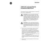
Figure 4
EMC Enclosure Kits – 1336S/F/T-AE4 and -AE5
1. Mount the bottom plate to the chassis using the supplied screws.
2. 1336
PLUS II drives using the AE4 Enclosure Kit require
replacement of a ribbon cable. Remove the ribbon cable between
the Main Control Board and Gate Drive Board (see Figure 4).
Replace this cable with the new supplied cable (with ferrite
block). Position the cable/block as needed to prevent obstruction
with the enclosure being installed.
3. Slide enclosure assembly over chassis as shown.
4. Fasten the assembly to the chassis using the supplied screws.
Tighten all screws to 1.5 N-m (13 lb.-in.).

1336 PLUS, 1336 PLUS II & 1336 FORCE™ NEMA Type 1 Enclosure Kit 3
Replace Ribbon Cable
(1336F-AE4 Only)
Figure 1
1336S/F-AA2 & AA3 Enclosure Kits
Figure 2
1336S/F-AE2 & AE3 EMC Enclosure Kits
Figure 3
1336S/F/T-AA4 & AA5 Enclosure Kits
Figure 4
1336S/F/T-AE4 & -AE5 EMC Enclosure Kits

4 1336 PLUS, 1336 PLUS II & 1336 FORCE™ NEMA Type 1 Enclosure Kit
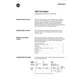
Door Grounding Jumper
Jumper must be Installed inside
Enclosure between Enclosure Door
(Grounding Stud) and Chassis
Grounding Stud.
Figure 5
Enclosure Kits – 1336S/F/T-AA6 and -AA7
EMC Enclosure Kits – 1336S/F/T-AE6 and -AE7
For CE conformance, the EMI gasket (pre-installed) and jumper (see
below) supplied with the 1336S/F/T-AE6 & AE7 must be in place.
1. Slide the side plates over the chassis tabs as shown.
2. Attach the top and bottom plates to the side plates by
sliding the tabs into the corresponding slots. Fasten the
assembly to the chassis using the supplied screws. Tighten
all screws to 2.8 N-m (25 lb.-in.).
3. Install the door on the side plate hinge pins.
4. For EMC Kits - locate the supplied jumper wire and fasten
one end to the chassis ground stud. The other end must be
fastened to the stud located in the lower corner of the door.
Rockwell Automation helps its customers receive a superior return on their investment by bringing
together leading brands in industrial automation, creating a broad spectrum of easy-to-integrate
products. These are supported by local technical resources available worldwide, a global network
of system solutions providers, and the advanced technology resources of Rockwell.
Worldwide representation.
Argentina • Australia • Austria • Bahrain • Belgium • Bolivia • Brazil • Bulgaria • Canada • Chile • China, People’s Republic of • Colombia • Costa Rica • Croatia • Cyprus
Czech Republic • Denmark • Dominican Republic • Ecuador • Egypt • El Salvador • Finland • France • Germany • Ghana • Greece • Guatemala • Honduras • Hong Kong
Hungary • Iceland • India • Indonesia • Iran • Ireland • Israel • Italy • Jamaica • Japan • Jordan • Korea • Kuwait • Lebanon • Macau • Malaysia • Malta • Mexico
Morocco • The Netherlands • New Zealand • Nigeria • Norway • Oman • Pakistan • Panama • Peru • Philippines • Poland • Portugal • Puerto Rico • Qatar • Romania • Russia
Saudi Arabia • Singapore • Slovakia • Slovenia • South Africa, Republic of • Spain • Sweden • Switzerland • Taiwan • Thailand • Trinidad • Tunisia • Turkey • United Arab Emirates
United Kingdom • United States • Uruguay • Venezuela
Rockwell Automation Headquarters, 1201 South Second Street, Milwaukee, WI 53204-2496 USA, Tel: (1) 414 382-2000, Fax: (1) 414 382-4444
Publication 1336 PLUS-5.6 – July, 1998 P/N 74001-008-01 (02)
Supersedes February, 1998 Copyright 1998 Rockwell International Corporation. All rights reserved. Printed in USA.
Figure 5
1336S/F/T-AA6 & -AA7 Enclosure Kits
1336S/F/T-AE6 & -AE7 EMC Enclosure Kits
/