Page is loading ...

DP/N: 4PFX020-020 v1.1 04/24/06
S U P E R C H A R G E R S
Owner’s Installation Guide for the
Paxton Automotive
Novi 2000 Supercharger
for the
1985 5.0L Ford Mustang
Paxton Automotive . 1300 Beacon Place . Oxnard CA 93033
805 604-1336 . FAX (805) 604-1337

ii
P/N: 4PFX020-020
©2006 Paxton Automotive
All Rights Reserved, Intl. Copr. Secured
24APR06 v1.1 MusGT(4PFX..020 v1.1)
©
2006 PAXTON AUTOMOTIVE
All rights reserved. No part of this publication may be reproduced, transmitted, transcribed, or translated into
another language in any form, by any means without written permission of Paxton Automotive.
T
his manual provides information on the installation, mainte-
nance and service of the Paxton supercharger kit expressly
designed for the 1985 5.0 Ford Mustang Contact Paxton
Automotive Corporation for any additional information regarding
this kit and any of these modifications at (805) 604-1336 8:00am-
4:30pm PST.
An understanding of the information contained herein will help
novices, as well as experienced technicians, to correctly install and
receive the greatest possible benefit from their Paxton supercharger.
When reference is made in this manual to a brand name, number,
specific tool or technique, an equivalent product may be used in
place of the item mentioned. All information, illustrations and speci-
fications contained herein are based on the latest product information
available at the time of this publication. All rights reserved to make
changes at any time without notice.
FOREWORD

iii
P/N: 4PFX020-020
©2006 Paxton Automotive
All Rights Reserved, Intl. Copr. Secured
24APR06 v1.1 MusGT(4PFX..020 v1.1)
TABLE OF CONTENTS
FOREWORD . . . . . . . . . . . . . . . . . . . . . . . . . . . . . . . . . . . . . . . . . . . . . . . . . . . . . . . . . . .ii
TABLE OF CONTENTS . . . . . . . . . . . . . . . . . . . . . . . . . . . . . . . . . . . . . . . . . . . . . . . . .iii
IMPORTANT NOTE . . . . . . . . . . . . . . . . . . . . . . . . . . . . . . . . . . . . . . . . . . . . . . . . . . . .iv
TOOL & SUPPLY REQUIREMENTS . . . . . . . . . . . . . . . . . . . . . . . . . . . . . . . . . . . . . .v
PARTS LIST (1985 Ford 5.0L Mustang) . . . . . . . . . . . . . . . . . . . . . . . . . . . . . . . . . . . . .vii
1. PREPARATION AND REMOVAL . . . . . . . . . . . . . . . . . . . . . . . . . . . . . . . .1-1
1.1 PREPARATION AND REMOVAL . . . . . . . . . . . . . . . . . . . . . . . . . . . . . . . . .1-1
2. SUPERCHARGER OIL DRAIN AND OIL FEED ASSEMBLY . . . . . . . . . .2-1
2.1 SUPERCHARGER OIL FEED ASSEMBLY . . . . . . . . . . . . . . . . . . . . . . . . . .2-1
2.2 SUPERCHARGER OIL DRAIN ASSEMBLY . . . . . . . . . . . . . . . . . . . . . . . .2-1
3. SUPERCHARGER BRACKET ASSEMBLY AND MOUNTING . . . . . . . . . .3-1
3.1 SUPERCHARGER BRACKET ASSEMBLY . . . . . . . . . . . . . . . . . . . . . . . . .3-1
3.2 CRANK PULLEY ASSEMBLY . . . . . . . . . . . . . . . . . . . . . . . . . . . . . . . . . . .3-1
4. FUEL PUMP REPLACEMENT . . . . . . . . . . . . . . . . . . . . . . . . . . . . . . . . . .4-1
4.1 FUEL PUMP REPLACEMENT . . . . . . . . . . . . . . . . . . . . . . . . . . . . . . . . . . .4-1
5. CARBURETOR ENCLOSURE INSTALLATION . . . . . . . . . . . . . . . . . . . . .5-1
5.1 CARBURETOR ENCLOSURE INSTALLATION . . . . . . . . . . . . . . . . . . . . .5-1
5.2 THROTTLE CABLE INSTALLATION . . . . . . . . . . . . . . . . . . . . . . . . . . . . .5-3
6. AIR INLET INSTALLATION . . . . . . . . . . . . . . . . . . . . . . . . . . . . . . . . . . . .6-1
6.1 AIR INLET INSTALLATION (On Passenger’s Side) . . . . . . . . . . . . . . . . . . .6-1
7. SUPERCHARGER DISCHARGE . . . . . . . . . . . . . . . . . . . . . . . . . . . . . . . . .7-1
7.1 SUPERCHARGER DISCHARGE . . . . . . . . . . . . . . . . . . . . . . . . . . . . . . . . .7-1
8. FINAL CHECK OUT AND START UP . . . . . . . . . . . . . . . . . . . . . . . . . . . . .8-1
8.1 INSPECT THE FOLLOWING . . . . . . . . . . . . . . . . . . . . . . . . . . . . . . . . . . . .8-1
8.2 PERFORM THE FOLLOWING . . . . . . . . . . . . . . . . . . . . . . . . . . . . . . . . . . .8-1
8.3 CHECK FOR THE FOLLOWING . . . . . . . . . . . . . . . . . . . . . . . . . . . . . . . . .8-1
APPENDIX . . . . . . . . . . . . . . . . . . . . . . . . . . . . . . . . . . . . . . . . . . . . . . . . . . . . .A-1
1016611 Asy, Mounting Bracket 5.0 Novi 2000 . . . . . . . . . . . . . . . . . . . . . . . . . . .A-2
1016710 Asy, Crank Pulley 86-93 5.0 Novi 2000 . . . . . . . . . . . . . . . . . . . . . . . . . .A-3

iv
P/N: 4PFX020-020
©2006 Paxton Automotive
All Rights Reserved, Intl. Copr. Secured
24APR06 v1.1 MusGT(4PFX..020 v1.1)
T
his kit will require the purchase of a 4150 based
Holley or Demon carburetor with mechanical sec-
ondaries.
IMPORTANT NOTE

v
P/N: 4PFX020-020
©2006 Paxton Automotive
All Rights Reserved, Intl. Copr. Secured
24APR06 v1.1 MusGT(4PFX..020 v1.1)
1985 Ford Mustang
Carbureted System
Installation Instructions
PLEASE READ CAREFULLY
This kit should only be installed by qualified mechanics. It is imper-
ative that the correct air/fuel mixture be maintained at all times.
This Kit is to be supplied to competent engine tuners for their
completion by the addition of, and tuning of, an appropriate
carburetor unit.
This product is intended for use on healthy, well maintained engines.
Installation on a worn-out or damaged engine is not recommended
and may result in failure of the engine.
Paxton Automotive is not responsible for engine damage.
Installation on new engines will not harm or adversely affect the
break-in period so long as factory break-in procedures are followed.
This kit is not smog legal for on-highway use.
For best performance and continued durability, please take note of the
following key points:
1. Use only premium grade fuel 91 octane or higher (R+M/2).
2. The engine must have stock or lower than stock compression ratio.
3. If the engine has been modified in any way, check with Paxton prior to
using this product.
4. Always listen for any sign of detonation (pinging) and discontinue hard
use (no boost) until problem is resolved.
5. Perform an oil and filter change upon completion of this installation and
prior to operating the vehicle.Thereafter, always use a high grade SF
rated engine oil or a high quality synthetic, and change the oil and filter
every 3000 miles.
TOOL AND SUPPLY REQUIREMENTS:
• Factory Repair Manual
• 3/8" Drive and Socket Set: SAE and Metric
• 1/2" Drive and Socket Set: SAE and Metric
• Open End Wrenches: SAE and Metric
• Center Punch
• SF Rated Quality Engine Oil
• Loctite Sealer #RC-609
• Oil Filter, and Wrench
• Heavy Grease
• Silicone Sealer
• Teflon Paste Sealant
• TAP, 3/8-18 NPT

vi
P/N: 4PFX020-020
©2006 Paxton Automotive
All Rights Reserved, Intl. Copr. Secured
24APR06 v1.1 MusGT(4PFX..020 v1.1)
N
ever rely solely on a hydraulic lift, when
working under a vehicle. Always use
approved jackstands to support the vehicle
and place them under the manufactures recom-
mended lift points.
When lifting the vehicle, make sure it is on a level
surface, preferably concrete or asphalt. The trans-
mission should be in “PARK” or “FIRST”, the
parking brake engaged, and the wheels blocked.
Never start the car with out first verifying that the
transmission is in neutral and the parking brake is
set.
Never remove the radiator cap while the engine is
still hot. Always wear eye protection when using
power tools such as drills, saws, grinders, etc., or
when working under a vehicle.
Never smoke, use an open flame, or have spark-
producing items around gasoline or flammable sol-
vents. Always have a fire extinguisher rated for
chemical and electrical fires handy when working
on motor vehicles.
Run engines only in a well ventilated area.
Carbon monoxide, gasoline and solvent vapors are
colorless, and sometimes odorless. These can
asphyxiate or explode without warning.
Always disconnect at least the (-) negative or
ground terminal of the battery when doing any
electrical, fuel system, or under dash work.
We look forward to hearing from you, particularly
if you have any comments or suggestions regarding
this manual at (805) 604-1336 Paxton Automotive
Corporation, 1300 Beacon Place, Oxnard, CA
93033. E-mail Address:
***NOTE***
Through these procedures the word “discard” is
used periodically in relationship to items that will no
longer be utilized in conjunction with the supercharg-
er installation. It is recommended that these items be
saved for future use should it become necessary.

vii
P/N: 4PFX020-020
©2006 Paxton Automotive
All Rights Reserved, Intl. Copr. Secured
24APR06 v1.1 MusGT(4PFX..020 v1.1)
PART NO. DESCRIPTION QTY. PART NUMBER DESCRIPTION QTY.
IMPORTANT: Before beginning installation, verify that all parts are included in the kit. Report any shortages or damaged
parts immediately.
1985 Ford 5.0L Mustang
Part No. 1001845
PARTS LIST
S U P E R C H A R G E R S
8PM205-012 CARB. ENCL ASY, PAXTON SBF 1
7A312-078 5/16-18 x 3/4" SHCS, S’STL 16
7A312-252 STUD, 5/16" - 2.1/2" CARB ENCLOSURE 4
7C011-050 10-32 PLUG SCREW 1
7F312-024 5/16-24 JAM NUT 4
7J312-000 5/16" FLAT WASHER-SAE 4
7F187-102 -3 BULKHEAD FITTING TO 1/4" HOSE 3
7P187-103 PLUG, -3 O-RING PORT 1
7P250-084 1/4"NPT x 1/2" x 90° BARB 1
7P375-104 PLUG, 3/8-16, BRASS, SHORT 3
7P500-087 PLUG, AN-8 O-RING PORT 3
7U100-003 O-RING 3-903 4
7U100-008 O-RING 3-908 3
7U100-020 10-32 GASKET 1
8M001-017 HOLLEY 4-BARREL BASE GASKET 2
8M001-018 GASKET, 90mm THROTTLE BODY 1
8PM003-051 CARB. COVER, PAXTON MACH. 1
8PM105-012 CARB. ENCL. LOWER w/BUSHING, SBF 1
1016611 ASY, MTG BRKT, 5.0 N2K 1
1210508 ASY, PULLEY SMOOTH FACE 2
2A017-875-11 SPACER, .875"OD x 1.482" LONG 4
4FA011-021 MOUNTING BRACKET, S/C 1
4FA015-015 ALTERNATOR STAY - PLATED 1
4FA017-021 SPACER, SMOG PUMP 1
4PFA010-031 BRACKET, IDLER ADJUST SCREW 1
4PFA010-044 PLATE, REAR S/C MTG, NOVI 2K 1
4PFA010-054 PLATE, FRONT S/C MTG BRACKET, NOVI 1
4PFA017-011 COLLAR, 10-RIB PLY, NOVI 2
4PFA017-071 SPACER, BRACKET, DUAL 1.482 1
7A250-077 1/4-20 x .75" FLAT ALLEN GR5 2
7A375-100 3/8-16 x G5 HHCS, PLT 2
7A375-102 3/8-16 x 1" FHCS, ZINC, PLT 3
7A375-124 3/8-16 x 1-1/4" HHCS, G5, PLATE 4
7A375-175 3/8-16 x 1-3/4 HXHD GR5 PLT 1
7A375-200 3/8-16 x 2" HXHD GR5 PLTD 1
7A375-251 3/8-16 x 2-1/2" FLAT SHCS 1
7A375-300 3/8-16 x 3" HXCS GP5 P 3
7A375-302 3/8-16 x 3.0 FLAT HD PLATED 2
7A375-625 3/8-16 x 6-1/4" HXHD 1
7A375-650 3/8-16 x 6-1/2" HX GR5 ZINC 1
7A375-675 3/8-16 x 6.75" HXHD GR5 ZINC 1
7A375-751 3/8-16 x 7.5" HXHD GR8 ZINC 1
7A437-175 7/16-14 x 1.75 HXHD ZINC PLT 1
7B500-300 1/2-20 x 3.00" HXHD GR5 ZINC 1
7F375-016 3/8-16 HX NUT 2
7F500-025 1/2-20 HEX NUT PLATED GR5 2
7J375-044 3/8"SAE WASHER PLATED 17
7J438-081 7/16"SAE WASHER, PLATED 2
7J500-001 WASHER, 1/2"ID x 1.12"OD 3
7PA375-500 SCREW, IDLER ADJUST, 5.00" 1
7PB500-263 ARBOR, S/C TENS PLY, 5.0 N2K 1
1016710 ASY, CRANK PULLEY 1
2A041-568 BELT, DAYCO 5100568 10-RIB 1
2A046-888 BELT, 6-RIB x 88.82" EFFECT. LE 1
4FA018-023 4.75/6.87" 10-GRV CRANK PULLEY 1
7A375-158 3/8-16 x 1.5" SHCS GR8 PLTD 4
7K375-040 3/8"AN960 FLAT WASHER PLATED 4
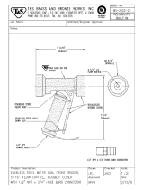
4FA114-023 RADIATOR HOSE ASY 1
4FA114-011 RADIATOR PIPE POLISHED 1
7R002-024 #24 SAE TYPE “F” SS HOSE CLAMP 2
7000 INSPECTOR NUMBER 0
1017400 TENSIONER, BELT, KIT 1
4FA010-011 TENSIONER MTNG. BRACKET MACH 1
7A375-124 3/8-16 x 1-1/4" HHCS, G5, PLATE 2
7A500-350 1/2-13 x 3-1/2" CARRIAGE 1
7F375-016 3/8-16 HEX NUT 1
7F500-013 1/2-13 HEX NUT 1
7J375-044 3/8"SAE WASHER, PLTD 1
7J500-001 WASHER, 1/2"ID x 1.12"OD 1
4FA130-036 OIL DRAIN ASY 1
7U030-036 1/2" OIL DRAIN HOSE 2
7P375-017 3/8"NPT x 1.2" BEADED HOSE BARB 1
7R001-008 #8 STNL HOSE CLAMP 2
70000 INSPECTOR NUMBER 0
1016420 S/C ASY, 5.0 CARB. SERP N2K CUR 1
4PFX101-001 FUEL PUMP ASY, SBF CARB MECH. 1
7P125-016 1/.8"NPT PLUG 1
7P250-043 1/4"NPT x 5/16" BARB 1
7P250-047 1.4"NPT x 3/8" BARB x 90° 1
7P250-141 -6 JIC PUSH ON HOSE END, 90° 1
7P500-083 -8 HOSE END STR, AL PUSH-ON 1
7P500-084 MAKE JIC TEE, -8, -6, -6 1
7P500-085 FTG, BULKHEAD -8 w/o RING 1
7P500-086 -8 HOSE END, PUSHLOC 120° 1
7P500-087 PLUG, AN-8 O-RING PORT 1
7P500-089 NUT, -8 BULKHEAD BLACK 1
7P500-377 -8 JIC MAKE ORB TO -6 MAKE FLA 1
7R001-006 #6 STNLS HOSE CLAMP, NARROW 4
7U030-046 5/32" VACUUM LINE 4.5'
7U032-016 3/8" EFI FUEL HOSE, HI-PSR 2.5'
7U037-030 -8 USCG FUEL HOSE, PUSH-ON .45'
7U100-008 O-RING 3-908 3
8F001-120 FUEL PUMP, SBF MECH, 120 GPH, 6-PSI 1
8H040-020 FUEL FILTER, INLINE 3/8" 1
1017300 ASY, SMOG PUMP MOD. 1
4PFA012-101 MACH, SMOG PUMP ELBOW 1
7P375-075 3/4" HOSE BARB UNION, BRASS 1
7R002-010 #10 SAE TYPE “F” SS HOSE CLAMP 4
7U038-030 1/4" VACUUM HOSE 1'
7U038-000 3/4" HEATER HOSE .30'
4PFX130-351 OIL FEED ASY, SBF, '69 351 1
7P125-004 1/8"NPT x 90° x -4 JIC FTG STL 1
7P250-034 1/4"NPT x 1/4"NPT STREET TEE 1
7P250-031 1/4"NPT x -4 JIC FLARE FTG STL 1
7U250-090-320 OIL FEED HOSE, 32" -4 x 90° 1
7U100-055 TIE-WRAP, 7.5" NYLON 2
4PFX212-050 ASY, AIR INTAKE 5.0 CARB SERP. 1
7PS400-200 SLEEVE, BLACK 4"OD x 2.0" 1
7R002-064 #64 SAE TYPE “F” SS HOSE CLAMP 2
4PFX012-051 ELBOW, 90° MOD CAST 4" x 3.5" w/HOL 1
7U035-001 3-1/2" FLEX HOSE 1'
7R002-052 #52 SAE TYPE “F” SS HOSE CLAMP 2
4H110-060 FLANGE ASY, AIR BOX S2000 1
7PS375-200 SLEEVE, BLACK Ø3.75" x 2.0"L 1
7R002-056 #56 SAE TYPE “F” SS HOSE CLAMP 2
4FA012-012 INTAKE ELBOW, 90° w/o BOSSES 1
8H040-030 AIR FILTER 3.5" FLG x 6"L 1
7U033-000 5/8" PCV HOSE 2'
7P250-048 1/4"NPT-5/8"BARB x 90° 1
7P250-047 1/4"NPT-3/8" BARB x 90° 1
7U030-046 5/32" VACUUM LINE 3.5'
7P375-075 3/4" HOSE BARB UNION, BRASS 1
7R002-010 #10 SAE TYPE “F” SS HOSE CLAMP 2
7E010-049 #10 x 3/4" HXHD SLF DRL SHT MTL 4
4PFX212-060 ASY, DISCHARGE 5.0L CARB. SERP. 1
4PFX012-021 MACH, DISCH TUBE, SBC CARB 1
7PS300-300 SLEEVE, BLACK, 3.0"OD x 3.0"L 1
7PS350-301 REDUCE, BLK 3.5-3.0 x 3.0L 1
7R002-044 #44 SAE TYPE “F” SS HOSE CLAMP 3
7R002-052 #52 SAE TYPE “F” SS HOSE CLAMP 1
7R002-016 #16 SAE TYPE “F” SS HOSE CLAMP 4
8D001-001 STD COMPRESS BYPASS VALVE 1
7U034-016 1" GS HEATER HOSE 1'
7P750-102 3/4"NPT x 1" x 90° HSE FIT 1
8M003-041 MACHINE, Ø3.5" FLANGE, SATIN 1
7U030-046 5/32" VACUUM LINE 1

viii
P/N: 4PFX020-020
©2006 Paxton Automotive
All Rights Reserved, Intl. Copr. Secured
24APR06 v1.1 MusGT(4PFX..020 v1.1)
PART NO. DESCRIPTION QTY. PART NUMBER DESCRIPTION QTY.
IMPORTANT: Before beginning installation, verify that all parts are included in the kit. Report any shortages or damaged
parts immediately.
1985 Ford 5.0L Mustang
Part No. 1001845
PARTS LIST
S U P E R C H A R G E R S
8M110-085 ASY, SUPPORT 5.0"L CARB SERP 1
7P375-045 3/8"NPT M/F x 45° STREET ELBOW 1
7U031-016 5/16" PCV/VAC RUBBER HOSE 2'
4PFA017-051 SPACER, FAN .510" PILOT NOVI 2
7U313-250 STUD, 5/16-24/24 x 2.5"4 1
7J312-000 5/16" FLAT WASHER, SAE 4
7L312-000 5/16" SPLIT (LCK) WASHER 4
7F312-021 5/16-24 NUT 4
5W013-000R 1/0 RED BATTERY CABLE 5'
5W001-029 LUG END TERMINALS 1/0 2
5W001-008 3/4" HEAT-SHRINK TUBING .33'
7A375-100 3/8-16 x 1" GS HHCS, PLT 2
7F312-017 5/16-18 NYLOCK NUT 2
7J375-044 3/8" SAE WASHER, PLTD 4
4GF055-010 WASHER, RESERVOIR GM TPI 1
7U313-300 STUD, 5/16-18/24 x 3.0" LG 4
8M001-019 GASKET, 4BRRL CARB. w/EGR FORD 1
8M017-021 SPACER, CARB. w/EGR BLK OFF 1
7U313-300 STUD, 5/16-18/24 x 3.0"LG 4
8M001-019 GASKET, 4BRRL CARB. w/EGR 1
8M017-021 SPACER, CARB. w/EGR BLK OFF 1
8M110-120 DEMON PLT BWL LINE ASY w/FTGS 1
88M010-120 FUEL LINE, SS FRONT DEMON 1
8M010-130 FUEL LINE, SS REAR DEMON 1
7P375-046 FTG, -6 TO 9/16-24 BG ADAPTER 2
8M110-080 ASY, THROTTLE, LINK '85 MUS 1
8M001-060 CABLE, THROTTLE 1
8M010-170 BRKT, CHVY THROTTLE CABLE 1
8M010-081 RETAINER, THROTTLE SPRING 2
8M010-190 BRKT, THROTTLE RETURN SPRING 1
2A017-750-03 SPACER, .750"OD x .130" LONG 1
2A017-032 SPACER, CARB. ENCLOSURE 1
7C010-052 10-24 x 1/2" BUTTON-HEAD SCREW 3
7C010-077 10-24 x 3/4" BUTTON-HEAD CAP SCREW 2
7C010-187 ROD END, 3/16", RH THREAD, w/NUT 1
7C010-188 ROD END, 3/16", LH THREAD, w/NUT 1
7F010-026 NUT, THROTTLE 1
7J010-001 #10 FLAT WASHER 8
7J010-687 WASHER, THROTTLE ENCLOSURE 1
8M010-040 THROTTLE ARM-INNER ENCLOSURE 2
8M010-050 THROTTLE SHAFT-ENCLOSURE 1
8M010-090 SPRING, THROTTLE ENCLOSURE 1
8M010-140 SHAFT, 5/16" HEX 1
7P375-104 PLUG, 3/8-16, BRASS, SHORT 1
4PFX020-020 MANUAL, 5.0 MUS. CR. SERP N2K 1
008575 S/C STRT INFO PKG ASY PAXT 1
3863515 DECAL, PAXTON COLOR 9" x 3" 1

1-1
P/N: 4PFX020-020
©2006 Paxton Automotive
All Rights Reserved, Intl. Copr. Secured
24APR06 v1.1 MusGT(4PFX..020 v1.1)
Section 1
PREPARATION AND REMOVAL
*** NOTE ***
If vehicle has gone more than 10,000 miles since it’s
last service. It is recommended that new spark plugs
(no platinum) be installed and that the ignition timing
be set to 6-8° initial uniess using an aftermarket tim-
ing box such as the MSD 6AL-BTM. The complete
ignition system should be in good working condition
before beginning installation. IE. distributor cap and
rotor, spark plug wires, etc.
1.1 Preparation and Removal.
A. Disconnect the battery cables; remove bat-
tery hold down, battery, and battery mount-
ing tray. Set these aside to reinstall later.
B. Remove the complete air cleaner assembly,
including the two plastic inlet Ducts located
in the inner fender wells (driver & passenger
sides). (See Fig. 1-a.)
Fig. 1-a
Fig. 1-b
C. Disconnect the electric choke wire from the
carb. and cut at the alternator harness.
D. Disconnect the fuel line from the carb.
Remove the throttle cable and bracket from
the car and discard. (See Fig. 1-b.)
Fig. 1-c
Fig. 1-d
E. Disconnect all vacuum, pcv, and egr lines
from the carb. Labeling each lines function
will help to reinstall to their correct posi-
tions later.
F. Remove the four retaining nuts and washer
securing the carburetor to the manifold.
Remove the carburetor, EGR plate, and four
studs from the manifold. Discard these
items.
G. Remove the Thermal Vacuum Switch at the
rear of the manifold. Using the supplied 45º
brass street elbow, reinstall the switch point-
ing to the passenger side rear of the vehicle.
Reconnect the thermal switch plug. This will
allow clearance for the carburetor enclosure.
(See Figs. 1-c, 1-d.)
*** NOTE ***
Use pipe sealant on the threads of both the fitting
and the switch.
THERMAL VACUUM
SWITCH

1-2
P/N: 4PFX020-020
©2006 Paxton Automotive
All Rights Reserved, Intl. Copr. Secured
24APR06 v1.1 MusGT(4PFX..020 v1.1)
Fig. 1-e
H. Disconnect the slide connection plug on the
coil. Remove the coil and coil bracket from
the manifold. Reinstall the coil in it’s origi-
nal bracket to the A/C bracket bolt. (See Fig.
1-e.)
M. Thoroughly clean the intake manifold carbu-
retor flange. Thread the supplied (4) carbu-
retor studs into the intake manifold. And
install one of the supplied gaskets.
Fig. 1-g
Fig. 1-h
Fig. 1-f
Split the wire loom to gain the necessary
wire length to reach the new coil location.
Reconnect the slide connector to the coil. (If
enough length can not be obtained use the
supplied wire and butt connectors to length-
en.)
*** NOTE ***
If a longer coil wire is needed, source a universal coil
wire kit that can be used. However, this would be a
good time to replace a worn wire set.
I. On the passenger side of the A/C condenser,
remove the A/C line support bracket and dis-
card. (See Fig. 1-f.)
J. Relocate the starter solenoid to the driver’s
side just in front of the shock tower. (See
Fig. 1-g.)
The ignition switch wire (and any other
wires drawing power from the solenoid) will
need to be extended to the new location.
K. Relocate the battery tray to the driver’s side.
Use the two 3/8" x 1" bolts, washers, and
nuts provided to secure the tray to the
engine compartment. Re-install the battery
and factory battery hold down. The battery
ground cable should be grounded to the
engine block. The battery positive cable is
reconnected to the starter solenoid. The
starter cable will need to be replaced with
the longer cable provided to reach the sole-
noids new location. Route and secure away
from heat and moving parts.
L. Locate the steel vacuum tube near the driv-
ers side valve cover. Using the supplied
5/16" x 24" rubber hose, connect this to the
vacuum tree on the firewall. Route as shown
or for best possible carburetor linkage clear-
ance. (See Fig. 1-h.)
A/C LINE
SUPPORT BRACKET
STARTER SOLENOID
IN NEW LOCATION
STEEL
VACUUM TUBE

1-3
P/N: 4PFX020-020
©2006 Paxton Automotive
All Rights Reserved, Intl. Copr. Secured
24APR06 v1.1 MusGT(4PFX..020 v1.1)
N. Loosen the petcock at the bottom of the
radiator and drain approximately one gallon
of coolant into a drain pan. (Save fluid for
re-use.)
O. Disconnect the overflow hose from the neck
of the radiator. Remove the coolant bottle
and discard.
P Using a 7/16" combination wrench, loosen
the four bolts that are securing the fan to the
water pump. With an18mm combination
wrench release the tension on the belt ten-
sioner and remove the factory drive belt.
Now remove the four bolts that are securing
the fan to the water pump. (See Figs. 1-i.)
Fig. 1-i
Q. Using a 10mm socket & ratchet or screw
driver, loosen the clamps and remove the
upper radiator hose from the vehicle. Save
for re-use. (See Fig. 1-j.)
R. Using a 7/16" wrench or socket, remove the
two sheet metal screws securing the fan
shroud to the radiator core support and
remove the fan shroud, fan clutch and fan
from the vehicle. (See Fig. 1-k.)
Fig. 1-k
Fig. 1-j

1-4
P/N: 4PFX020-020
©2006 Paxton Automotive
All Rights Reserved, Intl. Copr. Secured
24APR06 v1.1 MusGT(4PFX..020 v1.1)
X. Using a 9/16" socket and extension, remove
the remaining bolts securing the factory
bracket to the engine. Set the bracket aside,
this bracket will not be re-used.
Y. On the frame rail, there is an evaporator
canister. From underneath the vehicle, use a
1/2" socket and remove the two bolts secur-
ing the canister bracket to the frame rail.
Reposition the canister forward, towards the
front of the vehicle, using one of the stock
bolts. Resecure the canister to the frame rail
using the forward hole in the frame rail and
the rear hole in the bracket.
Fig. 1-m
T. Unplug the electrical connection at the alter-
nator, and using a 9/16" and a 1/2" socket,
remove the alternator from the factory
bracket. (See Fig. 1-m.)
U. Using a 5/16" nut driver, loosen the clamps
and remove the air injection hose from the
smog pump and diverter valve up next to the
valve cover. Disconnect the vacuum line
behind the smog pump and remove the hose
from the vehicle. Set aside for re-use
V. Remove the bolt at the rear of the smog
pump using a 9/16" socket and the two at
the front of the pump, remove the smog
pump from the vehicle.
W. For supercharger clearance, it is necessary to
replace the stock 90° hose port on the smog
pump with the smaller piece provided.
Locate the supplied assembly and replace
the stock piece now. (See Fig. 1-n.)
Fig. 1-l
Fig. 1-n
S. Using a 19mm wrench, loosen the bolt
securing the accessory drive belt tensioner to
the factory bracket and remove the tensioner
from the bracket. Set aside to be used in a
later step of the installation. (See Fig. 1-l.)

1-5
P/N: 4PFX020-020
©2006 Paxton Automotive
All Rights Reserved, Intl. Copr. Secured
24APR06 v1.1 MusGT(4PFX..020 v1.1)
Fig. 1-o
Z. Remove the four factory crank pulley bolts
with a 9/16" socket and extension and
remove the pulley from the vehicle. (See
Fig. 1-o.)

1-6
P/N: 4PFX020-020
©2006 Paxton Automotive
All Rights Reserved, Intl. Copr. Secured
24APR06 v1.1 MusGT(4PFX..020 v1.1)
This Page Left Intentionally Blank

2-1
P/N: 4PFX020-020
©2006 Paxton Automotive
All Rights Reserved, Intl. Copr. Secured
24APR06 v1.1 MusGT(4PFX..020 v1.1)
***IMPORTANT***
Before continuing, drain the motor oil from the vehi-
cle.
A. From underneath the vehicle you will need
to drill a pilot hole in the oil pan on the pas-
senger side by using a 1/8" drill bit approxi-
mately 1-1/2" from the top and 2" from the
front of the oil pan. (See Fig. 2-b.)
B. Upon completion of the drilled pilot hole,
insert a rigid thin piece of wire through the
drilled pilot hole to ensure that there is a
straight shot for the punch to go into. If
there is anything blocking the path, rotate
the engine by hand using the appropriate
size socket and ratchet, to rotate the crank-
shaft. Insert the punch into the pilot hole and
evenly enlarge the hole to 9/16".
C. Using a 3/8"NPT tap (not supplied) tap the
punched hole to accommodate the threaded
brass fitting. Before tapping, coat the tap
with thick lithium grease to retain the metal
shavings while you tap the oil pan.
Upon completion of the tapped oil pan hole,
coat the threaded end of the brass fitting
with silicone and thread into the oil pan, be
cautious not to over tighten or to strip the oil
pan threads.
Fig. 2-b
Section 2
SUPERCHARGER OIL DRAIN AND OIL FEED ASSEMBLY
2.1 Supercharger Oil Feed Assembly
2.2 OIL DRAIN ASSEMBLY
A. Remove the oil pressure sending unit locat-
ed near the oil filter. Apply clean motor oil
to the threads of the supplied street TEE.
Install the TEE with the branch facing the
front of the engine, referring to Fig. 3.1-a
for positioning.
B. Install the 1/8" x –4 fitting in the branch of
the TEE and connect the supplied oil feed
line. Route the line up toward the passenger
side valve cover behind the accessory brack-
ets. Secure line away from any moving
parts. Cap the line to prevent debris from
entering until the line is connected in a later
step.
C. Reinstall the factory oil pressure sending
unit in to the end of the street TEE, and con-
nect the factory wire harness.
Fig. 2-a

2-2
P/N: 4PFX020-020
©2006 Paxton Automotive
All Rights Reserved, Intl. Copr. Secured
24APR06 v1.1 MusGT(4PFX..020 v1.1)
This Page Left Intentionally Blank

3-1
P/N: 4PFX020-020
©2006 Paxton Automotive
All Rights Reserved, Intl. Copr. Secured
24APR06 v1.1 MusGT(4PFX..020 v1.1)
B. Attach the alternator stay bracket to the boss
on the bottom of the smog pump using the
3/8" x 1" bolt and washer provided. (See
Fig. 3-c.)
Fig. 3-b
3.2 Supercharger Bracket Assembly and
Mounting
A. Locate the supercharger mounting bracket
assembly #101661 and the cast supercharger
mounting bracket. Also locate the 3/8" x
6.5" long bolt, 3/8" x 6.25" bolt, the 3/8" x
2", and insert them into the rear of the cast
mounting bracket. (See Fig.3-b.)
Fig. 3-a
3.1 Crank Pulley Assembly
A. With the 4 supplied bolts 3/8 x 1 in length
install the new crank pulley and torque the
bolts to 25-28ft pounds. (See Fig. 3-a.)
Section 3
SUPERCHARGER BRACKET ASSEMBLY
ALTERNATOR
STAY
PAXTON
SUPPLIED
90° FITTING

3-2
P/N: 4PFX020-020
©2006 Paxton Automotive
All Rights Reserved, Intl. Copr. Secured
24APR06 v1.1 MusGT(4PFX..020 v1.1)
D. Install the large supercharger mounting plate
over the bolts that were previously installed
through the cast bracket. (See Fig. 3-e.)
*** NOTE ***
Leave these bolts loose. All bolts will be tightened
once the bracket is installed on the motor.
C. With the smog pump and the alternator as an
assembly. Slide them over the bolts previ-
ously installed into the cast bracket.
Locate the small spacer that will go between
the smog pump and the main supercharger
mounting bracket. Install this spacer onto
the upper-most bolt of the smog pump. (See
Fig. 3-d)
Fig. 3-d
Fig. 3-c
SPACER LOCATION

3-3
P/N: 4PFX020-020
©2006 Paxton Automotive
All Rights Reserved, Intl. Copr. Secured
24APR06 v1.1 MusGT(4PFX..020 v1.1)
Fig. 3-f
H. Bolt the Supercharger to the mounting
bracket with one of the 3/8" x 1" bolts and
washers through the upper most hole and the
two lower holes in the mounting plate. Place
the support plate over the front of the super-
charger and secure with the 3/8" counter-
sunk bolts. (See Fig. 3-f.)
E. Locate nuts and washers and secure the
supercharger mounting plate. Leave these
nuts loose.
Locate the 7/16-14 1.75" bolt and washer
and the 3/8-16 x 1.75" bolt and washer, the
3/8-16 x 6.75" bolt and washer. Install these
bolts as noted in Appendix #1016611.
Install this assembly as a unit to the engine
and tighten all bolts and nuts.
F. Install the 90° x -4 fitting using engine oil
only on the threads going into the super-
charger. Attach the oil drain hose to the fit-
ting and route the hose so there are no kinks
or dips. See that it is routed away from hot
or sharp objects and there are no kink or
dips in the line.
Fig. 3-e
G. Install the supercharger into the supercharg-
er mounting plate using three of the 3/8-16 x
1.25" bolts and the 3/8" washers. Refer to
Appendix #1016611 for their location. When
attaching the belt tensioner plate, it is rec-
ommended that the use of anti-seize be used
on the heads and threads of the counter-sunk
bolts.
I. Connect the oil drain hose to the previously
installed fitting in the oil pan. Secure using a
#8 hose clamp. Trim for best fit so there are
no kinks or sharp bends in the hose.
J. Connect the previously install oil feed line
to the -4 x 90° fitting on the supercharger.
Position as shown in Fig. 3-g and secure to
the bracket.
Fig. 3-g

3-4
P/N: 4PFX020-020
©2006 Paxton Automotive
All Rights Reserved, Intl. Copr. Secured
24APR06 v1.1 MusGT(4PFX..020 v1.1)
M. Install the 3/8" x 2 1/2" countersunk bolt
through the lower most hole in the support
plate and thread it into the mounting plate.
Do not tighten this bolt. (See Appendix
1016611.)
Fig. 3-i
Fig. 3-h
*** NOTE ***
You will have to route the accessory drive belt before
installing the supercharger belt tensioning plate. See
Appendix #1016710.
K. Locate the supercharger belt tensioning
plate. Assemble the idler pulley and super-
charger belt tensioning assembly. (See Fig.
3-h.)
L. Attach the supercharger belt tensioning plate
to the supercharger and rear supercharger
mounting plate using the spacers, bolts and
washers provided. Refer to Appendix
#1016611 for their location.
N. Above that, insert two of the 3/8" x 3 1/4"
bolts with washers through the support plate,
spacer and mounting plate. Secure the acces-
sory drive belt tensioner to the back of the
mounting plate with the upper of these two
bolts holes, the lower with the 3/8" x 1" bolt
and washer provided. Secure the other side
of the belt tensioner bracket to the stud at
the top of the water pump with the 3/8" nut
and washer. Do not tighten these bolts. (See
Fig. 3-j)
Fig. 3-j
O. There are three (3) countersunk holes left in
the support plate. They each take the
remaining 3/8" x 3 1/4" counter sunk bolts.
Install these bolts and tighten to 28-30 ft
pounds. Upon completion of this step, tight-
en all of the remaining bolts that have been
left hand tight, as well as the Smog and
alternator assemblies.
P Use the supplied 1/2" x 3 1/2" carriage bolt,
nut and washer to secure the factory belt
tensioner to the new bracket. Tighten nut to
28-30 ft lbs.. (See Figs. 3-j, 3-k.)
Fig. 3-k
/