Page is loading ...

DP/N: 4809625 - 97-01 5.2/5.9 Dodge v2.0 11/25/03
Owner’s Installation Guide for the
Paxton Automotive Novi 2000
Supercharger Kit
for the
1997/2001 5.2/5.9L DODGE
Paxton Automotive Corp . 1300 Beacon Place . Oxnard CA 93033
(805)604-1336 . FAX (805)604-1337

P/N: 4809625
©2003 Paxton Automotive
All Rights Reserved, Intl. Copr. Secured
25NOV03 v2.0 97-01 5.2/5.9 Dodge(4809625v2.0)
ii
T
his manual provides information on the installation, maintenance and service of
the Paxton supercharger kit expressly designed for the 1997-2001 5.2/5.9L
Dodge. Contact Paxton Automotive Corporation for any additional information
regarding this kit and any of these modifications at (805) 604-1336 7:00am-3:30pm
PST.
An understanding of the information contained herein will help novices, as well as
experienced technicians, to correctly install and receive the greatest possible benefit
from their Paxton supercharger. When reference is made in this manual to a brand
name, number, specific tool or technique, an equivalent product may be used in place
of the item mentioned. All information, illustrations and specifications contained here-
in are based on the latest product information available at the time of this publication.
All rights reserved to make changes at any time without notice.
© 2004 PAXTON AUTOMOTIVE
All rights reserved. No part of this publication may be reproduced, transmitted, transcribed, or translated
into another language in any form, by any means without written permission of Paxton Automotive.
FOREWORD

P/N: 4809625
©2003 Paxton Automotive
All Rights Reserved, Intl. Copr. Secured
25NOV03 v2.0 97-01 5.2/5.9 Dodge(4809625v2.0)
iii
FOREWORD . . . . . . . . . . . . . . . . . . . . . . . . . . . . . . . . . . . . . . . . . . . . . . . . . . . . . . . . . . . .ii
TABLE OF CONTENTS . . . . . . . . . . . . . . . . . . . . . . . . . . . . . . . . . . . . . . . . . . . . . . . . . . .iii
IMPORTANT NOTES . . . . . . . . . . . . . . . . . . . . . . . . . . . . . . . . . . . . . . . . . . . . . . . . . . . . .iv
1.1 - INTRODUCTION . . . . . . . . . . . . . . . . . . . . . . . . . . . . . . . . . . . . . . . . . . . . . . . . . . .1-1
2.1 - INITIAL PREPARATION AND DISASSEMBLY . . . . . . . . . . . . . . . . . . . . . . . . . . .2-1
3.1 - RELOCATION AND MODIFICATIONS . . . . . . . . . . . . . . . . . . . . . . . . . . . . . . . . . .3-1
4.1 - SUPERCHARGER INSTALLATION AND ASSEMBLY . . . . . . . . . . . . . . . . . . . . . .4-1
5.1 - FUEL SYSTEM MODIFICATIONS . . . . . . . . . . . . . . . . . . . . . . . . . . . . . . . . . . . . .5-1
6.1 - FINAL CHECK-OUT AND START-UP . . . . . . . . . . . . . . . . . . . . . . . . . . . . . . . . . . .6-1
APPENDICES . . . . . . . . . . . . . . . . . . . . . . . . . . . . . . . . . . . . . . . . . . . . . . . . . . . . . . . . . .18
TABLE OF CONTENTS

P/N: 4809625
©2003 Paxton Automotive
All Rights Reserved, Intl. Copr. Secured
25NOV03 v2.0 97-01 5.2/5.9 Dodge(4809625v2.0)
iv
RECOMMENDED TOOLS
FOR INST
ALLATION:
1. Metric and Standard sockets sets
2. Metric and Standard combination wrenches
3. Phillips and common screwdrivers
4. 12” crescent wrench or 36mm open end
wrenches
5. Pliers
6. Wire cutters and wire crimping tool
7. Hose cutters
8. 1/8” and 37/64” drill bit and hand drill
9. 12mm allen wrench
10. Small heat source
11. 3/8 NPT Tap
12. Ruler
13. Air Hammer
14. Air Compressor

P/N: 4809625
©2003 Paxton Automotive
All Rights Reserved, Intl. Copr. Secured
25NOV03 v2.0 97-01 5.2/5.9 Dodge(4809625v2.0)
1-1
Section 1
INTRODUCTION
C
ongratulations! You have purchased the
finest street Supercharger available for the
1997/2001 5.2/5.9L Dodge engine. The
centerpiece of this kit is the highly efficient and
reliable Paxton Automotive Corp. NOVI 2000
supercharger. A mechanically driven (by belt)
centrifugal blower (supercharger).
This kit comes with all of the parts you’ll need
for a successful installation. The operations
required have been grouped in order of sequence.
Photos and drawings accompany the text, allow-
ing quick orientation and parts identification.
Installation requires a selection of tools which
are listed in a table at the end of this section. We
also suggest that you obtain a Dodge shop manu-
al and become familiar with the details of your
cars systems. Manuals may be obtained from
your local Dodge dealer or you can order one
from Helm publications at (800) 782-4356.
For best results follow the instructions closely
and in sequence. The average installation time
for this kit is 8-10 hours. Your actual installation
time will depend on skill level and working con-
ditions. The estimate does not include time for
initial vehicle inspection, cleaning, fine tuning or
troubleshooting. Before even picking up a
wrench, read this entire manual. We are available
for technical assistance at (805) 604-1336, 7a.m.
- 3:30 p.m. Pacific Time.
After reading the manual, verify that all major
assembly groups are present in the main kit box.
You should have ample space to layout
the components. As you remove a box or bag
from the main kit, note the identification label
and compare it with the parts list. Please check
the box for small parts.
Paxton makes every effort to insure that all parts
are included in the box. However, if you discover
any missing or mislabeled parts, please contact
Paxton by phone for service.
Before starting the installation, we suggest your
engine compartment be clean. You can clean the
engine and compartment with a pressure washer
(such as those used at self serve car washes) and
a safe-for-aluminum cleaner/degreaser. Cover the
distributor with a plastic bag to prevent water
from entering.
*** CAUTION ***
We do not recommend proceeding with the kit installa-
tion unless your vehicle is within normal operating
parameters.
You are undoubtedly enthusiastic about getting
started on your project, but take just a little more
time to insure that your safety is not jeopardized.
A moment’s lack of attention can result in an
accident, as can failure to observe certain simple
safety precautions. The possibility of an accident
will always exist, and the following points should
not be considered a comprehensive list of all dan-
gers. Rather, they are intended to make you
aware of the risk and to encourage a safety con-
scious approach to all work you do on your vehi-
cle.
Never rely solely on a jack when working under
a vehicle. Always use approved jackstands to
support the vehicle and place them under the
manufactures recommended lift points.
When jacking the vehicle, make sure it is on a
level surface, preferably concrete or asphalt. The
transmission should be in “PARK” or “FIRST”,
the parking brake engaged, and the wheels
blocked.
Never start the car with out first verifying that
the transmission is in neutral and the parking
brake is set.
Never remove the radiator cap while the engine
is still hot. Always wear eye protection when
using power tools such as drills, saws, grinders,
etc., or when working under a vehicle.
Never smoke, use an open flame, or have spark-
producing items around gasoline or flammable
solvents. Always have a fire extinguisher rated
for chemical and electrical fires handy when
working on motor vehicles.

P/N: 4809625
©2003 Paxton Automotive
All Rights Reserved, Intl. Copr. Secured
25NOV03 v2.0 97-01 5.2/5.9 Dodge(4809625v2.0)
1-2
Run engines only in a well ventilated area.
Carbon monoxide, gasoline and solvent vapors
are colorless, and sometimes odorless. These can
asphyxiate or explode without warning.
Always disconnect at least the negative (-) termi-
nal of the battery when doing any electrical, fuel
system or under dash work.
We look forward to hearing from you, particular-
ly if you have any comments or suggestions
regarding this manual at (805) 604-1336 Paxton
Automotive Corporation, 1300 Beacon Place,
Oxnard, CA 93033, e-mail address info@paxto-
nauto.com
*** NOTE ***
Through these procedures the word “discard” is used
periodically in relationship to items that will no longer
be utilized in conjunction with the supercharger instal-
lation. It is recommended that these items be saved for
future use should it become necessary.

P/N: 4809625
©2003 Paxton Automotive
All Rights Reserved, Intl. Copr. Secured
25NOV03 v2.0 97-01 5.2/5.9 Dodge(4809625v2.0)
2-1
Fig. 2-a
Fig. 2-b
Fig. 2-c
Section 2
INITIAL PREPARATION AND DISASSEMBLY
Begin the initial preparation and disassembly
process by disconnecting the battery cables.
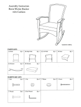
2-1 AIR INTAKE ASSEMBLY
A. Remove the nut from the top of the intake
bonnet and release clips holding the top of
the air box.
B. Remove plastic bonnet and air box cover
assembly. (See Fig. 2-a.)
C Remove plastic clip connecting air horn to
fender well. (See Fig. 2-b.)
D. Remove hardware, (two nuts and bolts)
holding air box to fender well and remove
airbox.
*** NOTE ***
You must remove air horn to gain access to one nut.
E. Remove factory bonnet hold down hard-
ware.
2-2 FAN AND FAN SHROUD REMOVAL
A. Start by removing fan clutch nut. (See Fig.
2-c.)
B. Remove four bolts holding fan shroud to
radiator.
C. Lift out fan shroud with fan and set aside.
(See Fig. 2-d.)
*** NOTE ***
You will have to modify the fan shroud before re-instal-
lation.
*** NOTE ***
Use factory tool or a 1 1/16 open-end wrench or a
large crescent wrench and a brass hammer.
Fig. 2-d

P/N: 4809625
©2003 Paxton Automotive
All Rights Reserved, Intl. Copr. Secured
25NOV03 v2.0 97-01 5.2/5.9 Dodge(4809625v2.0)
2-2
Fig. 2-h
Fig. 2-e
Fig. 2-f
Fig.. 2-g
B. Remove the bolt attaching the dipstick to
the alternator bracket. (See Fig. 2-f)
2-3 DISASSEMBLY OF ACCESSORY BELT,
COIL, AND BELT TENSIONER
A. Using a wrench on the accessory belt ten-
sioner, rotate the tensioner counter-clock-
wise and remove the accessory belt. (See
Fig. 2-e.)
*** NOTE ***
The coil bracket can be discarded, but the tensioner
and tensioner bracket will be re-used.
C. Remove the coil from the existing coil
bracket. (Coil will be relocated at a later
time.) Remove the two 10mm bolts and
nuts. Disconnect the plug from the coil.
(See Fig. 2-g.)
D. Remove the nuts and bolts(3) attaching the
tensioner bracket, coil bracket, stud and
nut from the front of the engine. (See
Fig. 2-h.)

P/N: 4809625
©2003 Paxton Automotive
All Rights Reserved, Intl. Copr. Secured
25NOV03 v2.0 97-01 5.2/5.9 Dodge(4809625v2.0)
3-1
Fig. 3-a
Fig. 3-b
Fig. 3-c
Fig. 3-d
Section 3
RELOCATION AND MODIFICATION
3-1 A/C DRIER RECEIVER RELOCATION
A. Use a 2 1/2" hole saw and cut a hole
between the horns. (See Fig. 3-a.)
B. Remove the receiver/drier from the stock
location and re-install into the new hole.
You will need to bend the hard lines. (See
Fig. 3-b.)
C. Re-mount the computer to the factory
bracket and re-install.
*** NOTE ***
This modification will gain clearance for the intake
duct.
3-3 COIL RELOCATION
A. Mount the coil relocation bracket with the
two screws provided. Use the existing
mounting stud to secure the bracket to the
engine. (See Fig. 3-d.)
*** NOTE ***
On '99-'01 vehicles, this step does not apply.
B. Cut these three mounting tabs just above
the case retaining screws. (See Fig. 3-c.)
B. Use the supplied wire and connectors to
extend the factory harness to the relocated
coil.
*** NOTE ***
This will take time to get them bent correctly to clear
the supercharger. You may need to re-bend them after
installing the supercharger bracket.
3-2 COMPUTER MODIFICATION
A. The computer is located on the passenger
side fender well. You will need to remove
the plugs and the three small screws hold-
ing it to the factory bracket.

P/N: 4809625
©2003 Paxton Automotive
All Rights Reserved, Intl. Copr. Secured
25NOV03 v2.0 97-01 5.2/5.9 Dodge(4809625v2.0)
3-2
This Page Left Intentionally Blank

P/N: 4809625
©2003 Paxton Automotive
All Rights Reserved, Intl. Copr. Secured
25NOV03 v2.0 97-01 5.2/5.9 Dodge(4809625v2.0)
4-1
Fig. 4-c
Fig. 4-b
Section 4
SUPERCHARGER INSTALLATION AND ASSEMBLY
4-1 S/C MOUNTING BRACKET
A. Remove the pulley from the stock acces-
sory belt tensioner and the tensioner from
the stock bracket for re-installation.
B. This is how the bracket should look
before you install it. (See Fig. 4-a.) Note
the accessory belt tensioner bracket. This
spacer will have to be removed before you
install the bracket. The dipstick goes
between the tensioner and the spacer.
*** NOTE ***
The idler pulley and pulley stand off have been
removed
C. Mount the bracket in the holes at the stock
accessory belt tensioner location. Remove
the two countersunk allen head bolts and
lower this arm to gain access to the bolt
securing the dipstick. (See Fig. 4-b.)
*** NOTE ***
When installing spacer, you may have to bend the dip-
stick. Try not to bend it too much. The more you bend
it, the harder it is to get in and out.
D. Re-install countersunk bolts.
E. This is how the spacer should look
installed. Short portion toward the engine
block. (See Fig. 4-c.)
Fig. 4-a
REMOVE THIS SPACER
BEFORE INSTALLING
BRACKET
4-2 CRANK PULLEY ASSEMBLY
A. Remove the center retaining bolt using a
31mm socket. Also remove the six outer
bolts.

P/N: 4809625
©2003 Paxton Automotive
All Rights Reserved, Intl. Copr. Secured
25NOV03 v2.0 97-01 5.2/5.9 Dodge(4809625v2.0)
4-2
Fig. 4-e
Fig. 4-g
AC
PUMP
IDLER
P/S
PUMP
WATER
PUMP
CRANK
PULLEY
ACCESSORY
TENSIONER
ALT
Fig. 4-f
Fig. 4-h
Fig. 4-d
H Install the tensioner using the factory nut
and washer. (Fig. 4-e.)
B. Install the spacer and pulley. Re-use the
factory center bolt and install the six bolts
and washers that are supplied in the kit.
Torque to factory specifications. (See Fig.
4-d.)
I. Re-install the factory tensioner pulley and
install the belt. (See Figs. 4-f, 4-g, 4-h.)
*** NOTE ***
On 1999-2001 vehicles follow the procedures
below.
4-3. CRANK PULLEY REMOVAL AND
INSTALLATION.
A. Loosen the large crank-pulley retain-
ing bolt.
B. Using the three-jaw pulley, slowly
remove the pulley. You will have to
use the retaining bolt to back up the
pulley so there will not be damage to
the crank threads.
C. Once you have the pulley removed
set aside it will not be reused.
D. With the supplied crank pulley rein-
stall the crank pulley. Using the fac-
tory retaining bolt slowly pull the
new pulley in to place. Take care not
to damage the threads.
E. Once the supplied pulley has been
installed, remove the factory retaining
bolt. Install the supplied dowel pins
and supplied supercharger pulley
spacer
*** NOTE ***
This spacer fits tight. Take care in installing this so as
not to damage it or the new crank pulley.
Reinstall the factory crank pulley
retaining bolt using locktite and torque
to factory specs.
F. Install the supplied supercharger pulley
using the supplied fasteners and lock-
tite.
G. Check the factory crank pulley belt for
alignment with accessories to assure
that the new crank pulley is properly
installed and seated.

P/N: 4809625
©2003 Paxton Automotive
All Rights Reserved, Intl. Copr. Secured
25NOV03 v2.0 97-01 5.2/5.9 Dodge(4809625v2.0)
4-3
Fig. 4-j
Fig. 4-i
4-4 SUPERCHARGER INSTALLATION
A. Install the idler Pulley Stand-off with the
hardware provided. Attach the supercharg-
er to the mounting bracket using the six
bolts provided.
C. Install the straight fitting for the oil feed
using sealant on the threads. Re-install the
factory sending unit in the outlet of the
brass TEE facing up.
D. Attach the 40" braided hose to the straight
fitting on the brass TEE and route the hose
toward the supercharger.
E. Attach the 90° fitting to the supercharger
oil jet using sealant on the non-flared end
of the fitting.
4-7 OIL DRAIN
A. Start by measuring down 2 1/2" on the
passenger’s side of the oil pan and make a
mark. From the second bolt from the front
of the oil pan, measure back 2 1/4" and
make another mark. In this location, drill
a 3/16" hole. With the hole drilled, take a
piece of wire and make sure that the rod
or crank is out of the way. You may have
to rotate the engine.
B. With the punch provided, start to enlarge
the hole. You will need to use an air-ham-
mer for this. If you try to use a standard
hammer it will destroy the pan. Use anti-
seize on the punch. By doing this, the
punch will go in easier. Be careful to only
go as deep as the shoulder. Test fit the tap
as you go, so you don’t make the hole too
large. The hole should be Ø9/16".
C. Using a 3/8 x 18NPT tap, begin tapping
the threads, but don’t go all the way in.
Remove the tap, apply sealant to threads
of the fitting provided.
D. Attach 18" hose to the tap and secure it
with the supplied hose clamp. Route the
hose up to the supercharger and attach.
C. Install the idler pulley on the idler pulley
stand off.
4-5 BELT TENSIONER
A. Install the supercharger belt tensioner on
the supercharger. The tensioner mounting
plate is secured to the front of the super-
charger with the supplied countersunk fas-
teners, followed by the tensioner, which
should be oriented as shown in appendix.
B. Route the supercharger belt as shown.
(See Fig. 4-k.)
4-6 OIL FEED
A. Remove the oil sending unit. This is locat-
ed at the rear of the engine next to the dis-
tributor.
B. Once you have removed the factory send-
ing unit, install the brass TEE that is pro-
vided.(See Fig. 4-j.)
B. Install the idler pulley stand off. (See Fig.
4-i.)
Fig. 4-k

P/N: 4809625
©2003 Paxton Automotive
All Rights Reserved, Intl. Copr. Secured
25NOV03 v2.0 97-01 5.2/5.9 Dodge(4809625v2.0)
4-4
Fig. 4-o
NEW LOCATION
PLUG
NEW MTG
HARDWARE
Fig. 4-p
Fig. 4-l
Fig. 4-m
Fig. 4-n
4-9 AIR DISCHARGE
A. Replace the stock intake bonnet mounting
hardware with the bonnet adapter that is
provided. (See Fig. 4-p.)
E. Relocate the stock air temp sensor from
the intake manifold to the air intake duct.
Use the supplied pipe plug in place of the
air temp sensor. (See Fig. 4-o.)
B. Install the bracket using the bolts, nuts,
and washers supplied in the kit. Attach the
air filter in the wheel well.
C. On the engine compartment side, attach
the sleeve to the, 90° elbow, and the hose
clamps. Connect the other end of the air
intake assembly to the supercharger.
D. The brass fitting connected to the air
intake duct, (see Fig. 4-m) attaches to the
plastic fitting on top of the driver’s side
valve cover. (See Fig. 4-n.)
A. Raise the car up on jack stands. Remove
the right front tire and the fender liner.
Using the air intake bracket as a template,
mark the area on the inner fender well
where the 3 1/2" hole and the 4 holes will
be drilled. (See Fig. 4-l.)
*** NOTE ***
On 1999-2001 vehicles, step ‘A’ will not apply. Refer to
Appendix 1015935.
4-8 AIR INTAKE

P/N: 4809625
©2003 Paxton Automotive
All Rights Reserved, Intl. Copr. Secured
25NOV03 v2.0 97-01 5.2/5.9 Dodge(4809625v2.0)
4-5
Fig. 4-r
E. Attach the fuel enrichment line to the fuel
fitting on the driver’s side fuel rail. You
will have to remove a plastic cap and a
schraeder valve to make this connection.
(See Fig. 4-q.)
4-11 FAN AND FAN SHROUD
REINSTALLATION
A. Install the new fan spacer to clear the new
lower crank pulley. (Fig. 4-s.)
C. Connect the air dicharge tube to the bon-
net.
D. Connect the other end of the discharge
tube to the supercharger.
B. Attach the bonnet with the supplied bolt
and washer.
4-10 COMPRESSOR BYPASS
A. Attach the compressor bypass hose to the
fitting on the air intake duct. (The other
hose will attach to the air discharge duct .)
Route the vacuum hose toward the driver
side. (See Fig. 4-r.)
Fig. 4-q
Fig. 4-s
Fig. 4-t
***NOTE***
Area to be trimmed is represented by the white dashed
line.
C. You will also need to trim approximatly
1-1/2" off the bottom of the fan shroud to
clear the crank pulley.
B. You will need to trim this area on the fan
shroud to clear the supercharger belt idler
pulley. (See Fig. 4-t.)

P/N: 4809625
©2003 Paxton Automotive
All Rights Reserved, Intl. Copr. Secured
25NOV03 v2.0 97-01 5.2/5.9 Dodge(4809625v2.0)
4-6
This Page Left Intentionally Blank

P/N: 4809625
©2003 Paxton Automotive
All Rights Reserved, Intl. Copr. Secured
25NOV03 v2.0 97-01 5.2/5.9 Dodge(4809625v2.0)
5-1
Fig. 5-a
Fig. 5-b
C. Drill holes and mount the fuel pump to the
driver’s side frame rail underneath the
vehicle using the supplied hardware. (See
Fig. 5-b.)
D. Route the fuel lines between the fuel
pump and fuel pressure regulator. Connect
the fuel line between the fuel pressure reg-
ulator and the fuel rail using the supplied
fitting. Connect the fuel line from the fuel
pump to the stock fuel line. Refer to
Appendix #1017735 for fuel pump assem-
bly procedure.
5-1 FUEL ENRICHMENT
A. Disconnect the stock fuel supply fitting at
the fuel rail.
B. Using the fuel pressure regulator as a tem-
plate, drill two .Ø145. holes and mount
the fuel pressure regulator to the firewall.
(See Fig. 5-a.)
Section 5
FUEL SYSTEM MODIFICATIONS
*** NOTE ***
Refer to Appendix #1017735 for fuel enrichment
assembly.
5-2 MSD TIMING RETARD BOX
INSTALLATION
A. Drill holes and Mount the MSD timing
retard to the the driver’s side inner fender
well at the front of vehicle. (See Fig. 5-c.)
Fig. 5-c
B Mount the boost retard switch where it can
easily be reached by the driver per the
instructions included with the MSD timing
retard box.
*** NOTE ***
This is also provided in the Appendix.

P/N: 4809625
©2003 Paxton Automotive
All Rights Reserved, Intl. Copr. Secured
25NOV03 v2.0 97-01 5.2/5.9 Dodge(4809625v2.0)
5-2
Fig. 5-e
Fig. 5-d
5-3 PAXTON ADDITIONAL INJECTOR
CONTROL INSTALLATION
A. Remove the fuse box cover located on the
driver’s side near the firewall. Using the
Paxton Injector Controller as a template,
drill two holes and connect the fueler to
the fuse box cover with the supplied hard-
ware. (See Fig. 5-d.)
B. Attach the Paxton Injector Controller
power wire to the wire from the relay (ter-
minal 87) with a female crimp connector.
(See Fig. 5-e.)
C Attach the Paxton Injector Controller
ground wire to the wire from the relay
(terminal 85) with a female crimp connec-
tor. Ground the unit to the fuse box
ground terminal.
*** NOTE ***
Refer to Appendix #1017736 for wiring diagram for
AIC Controller and fuel pump.
D. Using the relay as a template, drill a hole
in the fender well next to the MDS timing
master and mount relay with supplied
screws.
E. Hook up the vacuum lines as shown in
appendix. (Per schematic.)
*** NOTE ***
Connect the yellow wire with a black tracer to the tach
signal wire. This provides an RPM signal to the AIC
controller. Refer to the factory manual for tach signal
pin location. Since it varies from model year to model
year, it is advised that you look at a shop manual for
your vehicle to locate the correct wire color and pin
location.
G. Attach the ground wire to the pump.
Route the wires from relay to the AIC.
Route the wires from the relay to the bat-
tery (pos. terminal) inside the fuse box.
Attach the trigger wire from the relay to
the switched 12V source.
H. Drill a hole in the fender well for a
ground. Scrape and sand the paint off from
around the area to ensure a good connec-
tion. Attach the MSD timing master and
the relay terminal rings to the same
ground.
I. Route the injector plugs from the fueler
and attach to the injectors.
J. Attach the wiring harness from the MSD
unit to coil. (Tap into coil wires.) See page
5-3 for the wiring diagram.

P/N: 4809625
©2003 Paxton Automotive
All Rights Reserved, Intl. Copr. Secured
25NOV03 v2.0 97-01 5.2/5.9 Dodge(4809625v2.0)
5-3
Fig. 5-g
The following are samples of popular installations:
Follow the procedure shown below for vehicles with the TFI (thick film ignition). This
system is identified by the square coil with a single connector. Connect the MSD
Boost Timing Master Cable Assembly in the following manner:
1. Cut the wire between the coil connector and original wire harness.
2. Install the insulated male fastener (supplied in the parts kits) onto the ends of
the cut wire.
3. Plug the MSD BTM Cable Assembly WHITE wire into the wire going to the
original harness.
4. Plug the MSD BTM Cable Assembly
ORANGE wire into the wire going to
the coil connector.
5. Install the T-Tap Splice Connector
onto the wire and plug the 6" white
adapter cable into the Tap Splice
Connector (see Fig. B). Plug the MSD
TM Cable Assembly RED wire into the
6" white adapter cable (tape to prevent
shorting.
6. Connect the MSD BTM Cable
Assembly BLACK wire to a GROUND.
ORIGINAL
WIRE
WIRE
SPLICE
TAPE TO
PREVENT
SHORTING
RED WIRE
FROM BTM
CABLE
ASSEMBLY
CONNECTION
ORIGINAL WIRE
WIRE SPLICE
6" WHITE
ADAPTER
CABLE
SQUEEZE
WITH
PLIERS
THIS WIRE HAS THE TIMING AND
FIRING SIGNAL COMING FROM THE
FACTORY COMPUTER. THIS SIGNAL
NOW GOES TO THE MSD BTM TO BE
MODIFIED.
TO GROUND
ORIGINAL
WIRE
HARNESS
MSD BOOST
TIMING MASTER
P/N: 5462
THIS WIRE IS COMING
FROM THE IGNITION
SWITCH AND SUPPLIES
THE COIL+ AND MSD
BTM WITH 12 VOLTS.
BLACK
WHITE*
RED*
ORANGE*
THIS WIRE HAS THE
MODIFIED SIGNAL COMING
FROM THE MSD BTM AND
WILL TELL THE COIL WHEN
TO FIRE.
• CONNECTION
* TAPE TO PREVENT
SHORTING
COIL CONNECTOR
TFI COIL
SAMPLE APPLICATIONS
Fig. B
Fig. A

P/N: 4809625
©2003 Paxton Automotive
All Rights Reserved, Intl. Copr. Secured
25NOV03 v2.0 97-01 5.2/5.9 Dodge(4809625v2.0)
5-4
Congratulations!!! Here is your finished supercharger equipped engine!
Fig.5-h / Completed Engine Shot
/