Page is loading ...

© Copyright 2018-20, Continental Control Systems, LLC Specifications are subject to change without notice.
ctlsys.com 1-303-444-7422 Page 1 of 7 Doc ID: WND-WR-MB-DS1 2020-02-12
WND-WR-MB
WattNode Wide-Range Modbus Meter
The WattNode® Wide-Range Modbus Meter measures bi-
directional energy, power, voltage, current, etc. It
communicates using Modbus® RTU over RS-485. The
WattNode Wide-Range provides revenue-grade system
accuracy when used with the CCS Accu-CT® family of
revenue grade (C0.6 or better) current transformers.
Features
• One model can measure 100 to 600 Vac, single-phase
or three-phase, wye or delta services
• Modbus registers can reverse CT polarity and change
the assignment of CTs to voltage phases to correct
wiring errors
• ANSI C12.20 class 0.5 and ANSI C12.1 accuracy
• Works with any 0.333 Vac current transformers and
milliamp output CTs
• Line powered from 100 to 600 Vac
• Powered from line-to-neutral or line-to-line from any
of: VN to VA, VN to VB, or VA to VB
• Includes support for external potential transformers
Links
• Installation Guide: https://ctlsys.com/m/WND-WR-
MB-Install-Guide.pdf
• Reference Manual: https://ctlsys.com/m/WND-WR-
MB-Ref-Manual.pdf
• Product Web Page: https://ctlsys.com/p/wnd-wr-mb/
1 Models
Table 1: Models
Model
Communication
UL Listed
WND-WR-MB
Modbus/RTU
Yes
To get a certificate of calibration for the meter, separately order WN-CAL-CERT.
1.1 DIP Switches
The WND-WR-MB includes an eight-position DIP switch with the following switch functions. See the Installation Guide or
Reference Manual for more details.
1) Modbus address bit 1: down (0) = 0, up (1) = 1
2) Modbus address bit 2: down (0) = 0, up (1) = 2
3) Modbus address bit 3: down (0) = 0, up (1) = 4
4) Modbus address bit 4: down (0) = 0, up (1) = 8
5) Modbus address bit 5: down (0) = 0, up (1) = 16
6) Modbus address bit 6: down (0) = 0, up (1) = 32
7) RS-485 termination resistor: down (0) = no termination, up (1) = 120Ω termination
8) Modbus baud rate: down (0) = 9,600 baud, up (1) = 19,200 baud
1.2 Options
1.2.1 Communications Options
The communications options may be used to configure the Modbus address, baud rate, and other
communications parameters.
Note: The DIP switches are normally used to configure the Modbus address and baud rate, so these options
should only be used for special circumstances such as baud rates that cannot be specified with the DIP
switches. If you order a meter with an address option or a baud rate option, then the DIP switch will no longer
function to set the address or the baud rate.
Defaults: no parity, eight data bits, one stop bit

WND-WR-MB
© Copyright 2018-20, Continental Control Systems, LLC Specifications are subject to change without notice.
ctlsys.com 1-303-444-7422 Page 2 of 7 Doc ID: WND-WR-MB-DS1 2020-02-12
• Option AD=xxx – Set the Modbus slave address to xxx. This will prevent the DIP switch positions that set the
address from functioning.
• 1.2K - Set the baud rate to 1,200. This and the following baud rate options will prevent the DIP switch position
that set the baud rate from functioning.
• 2.4K - Set the baud rate to 2,400.
• 4.8K - Set the baud rate to 4,800.
• 9.6K - Set the baud rate to 9,600.
• 19K - Set the baud rate to 19,200.
• 38K - Set the baud rate to 38,400.
• 57K - Set the baud rate to 57,600.
• 76K - Set the baud rate to 76,800.
• 115K - Set the baud rate to 115,200.
• BAUD=xxx - Set the baud rate to xxx, where xxx may be 1200, 2400, 4800, 9600, 19200, 38400, 57600, 76800,
or 115200. The abbreviated baud rate options, such as 9.6K, are preferred.
• EP - Enable even parity (the default is no parity)
• 8N2 - Select two stop bits. The default is one stop bit.
• T1 - Install a fixed (non-switchable) 120Ω termination resistor and 1.2kΩ bias resistors (A- to Common and B+ to
3.3 Vdc). By default, the meter does not provide biasing. Selecting this option will remove the DIP switch position
7 switchable termination.
1.2.2 Meter Element Configuration Options
These are used to configure the ConnectionType or MeterConfig registers. By default, with none of these
options specified, the WND-WR-MB meter elements will function like the WNC series of meters.
Only one of the following two options may be specified for a particular meter.
• CTR=x - Set the ConnnectionType register to x (the default is 1). See the reference guide for more information.
Connec-
tion
Type
Name
Meter
Element
Mapping
CT
Positions
Service
Types Notes Meter
Config1
Meter
Config2
Meter
Config3
0 Custom Custom Varies Any
May not be used with
the CTR=x option
- - -
1 Wye
CT1-VAN
CT2-VBN
CT3-V
CN
CT1 Phase A
CT2 Phase B
CT3 Phase C
3-phase 4-
wire wye
May also be used for
delta and four-wire
delta services
10 20 30
2 Delta CT1-VAC
CT2-VBC
CT1 Phase A
CT2 Phase B
CT3 not used
3-phase 3-
wire delta
CT3 is not used.
Works
for grounded delta with
any phase grounded.
90 50 0
3 Branch
circuits
CT1-VAN
CT2-VAN
CT3-VAN
CT1 Phase A
CT2 Phase A
CT3 Phase A
1-phase,
2-wire with
neutral
Use for monitoring 1-3
neutral connected
branch circuits
10 10 10
4
House
and
Inverter
CT1-VAN
CT2-VBN
CT3-VAB
CT1 Phase A
CT2 Phase B
CT3 Phase A
See notes
1-phase, 3-wire with
neutral for CT1 and
CT2; 1-phase, 2-wire
without neutral for CT3
10 20 40
5 Line to
Line CT1-VAB
CT1 Phase A
CT2 not used
CT3 not used
1-phase,
2-wire (no
neutral)
CT2 and CT3 are not
used 40 0 0
• MCR=xx/yy/zz - Set MeterConfig1 to xx, MeterConfig2 to yy, and MeterConfig3 to zz. See the reference guide
for more information
The mapping from current transformer inputs to line voltage inputs is controlled with the MeterConfig
registers. There are one meter element and one configuration register for each current transformer. For
each meter element (CT), you can select the line voltage to be associated with that CT from the following
list:
o 0 = Disable meter element
o 10 = VAN (also called VA), mount CT around phase A conductor
o 20 = VBN (also called VB), mount CT around phase B conductor

WND-WR-MB
© Copyright 2018-20, Continental Control Systems, LLC Specifications are subject to change without notice.
ctlsys.com 1-303-444-7422 Page 3 of 7 Doc ID: WND-WR-MB-DS1 2020-02-12
o 30 = VCN (also called VC), mount CT around phase C conductor
o 40 = VAB, mount CT around phase A conductor
o 50 = VBC, mount CT around phase B conductor
o 60 = VCA, mount CT around phase C conductor
o 70 = VBA (equal to -VAB), mount CT around phase B conductor
o 80 = VCB (equal to -VBC), mount CT around phase C conductor
o 90 = VAC (equal to -VCA), mount CT around phase A conductor
The default settings for the MeterConfig registers follow. These match the behavior of the older WNB and
WNC meters:
o MeterConfig1 = 10
o MeterConfig2 = 20
o MeterConfig3 = 30
1.2.3 Current Transformer Options
Either of the following CT= options are recommended for easier installation.
• CT=xxx - Pre-assign xxx as the global CtAmps value for the current transformers.
• CT=xxx/yyy/zzz - Pre-assign xxx to CtAmps1, yyy to CtAmps2, and zzz to CtAmps3. This is used if non-
matching CTs are connected to different inputs.
The following options are only for use with non-standard current transformers (CTs), such as milliamp output
CTs, CTs with a full-scale output voltage other than 0.33333 Vac, or CTs that need some other adjustment.
• MA - Specify that the meter is designed for 40mA output CTs. Equivalent to "Opt R=10,V=0.4".
• R=xxx or R=xxx/yyy/zzz - Specify the addition of burden resistance for all three CT inputs or individually for
each CT input. This means a burden resistor is installed in the meter to allow use of a milliamp output CT. If this
option is not specified, then there are no burden resistors installed in the meter and the meter must be used with
0.333 Vac CTs (internally burdened millivolt output CTs). The xxx, yyy, and zzz values are the ohms of the
burden resistors. Contact the factory for supported values.
• V=xxx or V=xxx/yyy/zzz - Specify the full-scale CT output voltage for all three CT inputs or individually for each
CT input. If this option is not specified, then 0.33333 Vac is the default value. The xxx, yyy, and zzz values are
in units of volts. This supports values from 0.1 to 0.5 Vac. Values below 0.25 Vac may affect the accuracy for
low-current signals.
• PA=xxx or PA=xxx/yyy/zzz - CT phase adjustment in millidegrees. The first form uses xxx as the adjustment for
all three CTs. This option determines the values that are written to the PhaseAdjust1, PhaseAdjust2, and
PhaseAdjust3 configuration registers. Use negative values to compensate for a phase lead in the CT.
• L - Factory lock the CT amps rating, CT directions, CT gain adjust, CT phase adjust, PT ratio, and the creep limit
configuration registers. The CT=xxx option must be used with this because it will not be possible to set the CT
amps in the field. This option is recommended only if required due to security concerns.
2 Specifications
2.1 Accuracy
The following accuracy specifications do not include errors caused by the current transformer accuracy or
phase angle errors. “Rated current” is the current that generates a CT output voltage of 0.33333 Vac or
equivalent milliamp output.
Unless otherwise noted, all accuracy specifications assume the following conditions:
• Line voltage: 100 to 690 Vac
• Power factor (PF): 1.0
• Frequency: 48 - 62 Hz
• Ambient Temperature: 23°C ± 5°C
• CT Current: 1% - 100% of rated current
Parameter
Test Conditions
Typ Max
Unit
EnergySum, Energy1, 2, 3
(1)
(active energy)
elapsed time
(2)
>= 30 s
±0.2 ±0.5
%
EnergySum, Energy1, 2, 3; PF 0.5 to 0.9
elapsed time(2) >= 30 s
±0.4 ±0.8
%
PowerSum, Power1, 2, 3 (active power)
averaging >= 1 s
±0.3 ±0.5
%
PowerSum, Power1, 2, 3; PF 0.5 to 0.9
averaging >= 1 s
±0.5 ±1.0
%
VoltAN, BN, CN, VoltAB, BC, CA (RMS voltage)
averaging >= 1 s
±0.3 ±0.5
%

WND-WR-MB
© Copyright 2018-20, Continental Control Systems, LLC Specifications are subject to change without notice.
ctlsys.com 1-303-444-7422 Page 4 of 7 Doc ID: WND-WR-MB-DS1 2020-02-12
Parameter
Test Conditions
Typ Max
Unit
EnergySum, Energy1, 2, 3
(1)
(active energy)
elapsed time
(2)
>= 30 s
±0.2 ±0.5
%
Current1, 2, 3 (RMS current)
averaging >= 1 s
±0.25 ±0.5
%
Freq (frequency)
averaging >= 1 s
±50 ±150
±3 ±9
ppm
mHz
PowerFactor1, 2, 3
averaging >= 1 s, PF > 0.5
±0.5 ±1.0
%
EnergyReacSum, EnergyReac1, 2, 3 (reactive
energy)
elapsed time(2) >= 30 s,
PF < 0.9
±0.6 ±1.5
%
PowerReacSum, PowerReac1, 2, 3 (reactive power)
averaging >= 1 s, PF < 0.9
±0.6 ±1.5
%
EnergyAppSum, EnergyApp1, 2, 3 (apparent energy)
elapsed time
(2)
>= 30 s
±0.3 ±0.5
%
PowerAppSum, PowerApp1, 2, 3 (apparent power)
averaging >= 1 s
±0.3 ±0.5
%
(1) Note: when parameters are written like Energy1, 2, 3, this means Energy1, Energy2, and Energy3.
(2) Note: This indicates that energy accuracy should be evaluated over a period of 30 seconds or longer.
All models
• Meet the ANSI C12.1-2008 and ANSI C12.20-2010 class 0.5 accuracy requirements, excluding errors caused by
attached current transformers.
• Meet the ANSI C12.1-2014 standard for revenue metering with CTs with class 0.6 or better current transformers.
• Meet the ANSI C12.20-2015 class 0.5 standard for revenue metering with class 0.2 and class 0.3 current
transformers.
• Certified by MET Labs, Inc. to meet ANSI C12.1-2014 and C12.20-2015 Class 0.5 from 120 to 480 Vac, when
used with current transformer models TCL-B-100 Opt C0.3, ACTL-0750-200 Opt C0.6, or ACTL-1250-400 Opt
C0.3.
2.2 Measurement
• Update Rate: Approximately 0.1 second, adjusted to an integer number of AC line cycles. All measurements are
performed at this rate. All measurement registers except the energy registers can update as fast as every 0.1
seconds depending on the configuration of the Averaging register. The energy registers are updated from the
internal values every 1.0 second.
• Start-Up Time: ≤ 1 second after the supply voltage is applied.
• Default CT Phase Angle Correction: 0.0 degrees.
• Creep Limit: 0.04% (1/2500th) of full-scale.
2.3 Modbus Communication
• Protocol: Modbus RTU (binary)
• Baud Rates: 1200, 2400, 4800, 9600, 19200, 38400, 57600, 76800, and 115200
• Duplex: Half (two-wire plus common)
• Parity:
o Standard: N81 (no parity, eight data bits, one stop bit)
o Optional: E81 (even parity, eight data bits, one stop bit)
o Optional: N82 (no parity, eight data bits, two stop bits)
• Modbus Buffer: 256 bytes
• Communication Response Time: 5 - 25 milliseconds (may be longer immediately after a Modbus write
command, while values are saved to non-volatile memory).
2.4 Electrical
2.4.1 Power Supply
• Nominal Power Supply Voltage: 100 to 600 Vac
• Power Supply Input Terminals: Vn, Va, Vb (the meter supply can operate line-to-neutral or line-to-line)
• Power Supply Minimum Operating Voltage: 85 Vac
• Power Supply Absolute Maximum Voltage: 690 Vac. Exceeding this limit can damage the WattNode and void
the warranty.
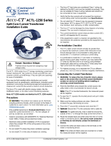
• Power Supply Typical Watts: see graph below
• Power Supply Typical Voltage-Amperes: see graph below

WND-WR-MB
© Copyright 2018-20, Continental Control Systems, LLC Specifications are subject to change without notice.
ctlsys.com 1-303-444-7422 Page 5 of 7 Doc ID: WND-WR-MB-DS1 2020-02-12
• Power Supply Typical Power Factor: 0.6
2.4.2 General Electrical
• Line Frequency: 45 to 65 Hz
• Nominal Line-to-Neutral Vac: 90 to 347 Vac
• Nominal Line-to-Line Vac: 120 to 600 Vac
• Over-Current Limit: 200% of rated current. Exceeding 200% of rated current will not harm the meter, but the
current and power will not be measured accurately.
• Maximum Surge: EN 61000-4-5: 2kV, ANSI C12.1 combination wave: 6kV, 1.2/50 μs – 8/20 μs
• Measurement Category: The line voltage measurement terminals on the meter are rated for CAT III, 600 Vac
Measurement Category III is for measurements performed in the building installation. Examples are
measurements on distribution boards, circuit-breakers, wiring, including cables, busbars, junction boxes,
switches, socket-outlets in the fixed installation, and equipment for industrial use and some other
equipment, for example, stationary motors with a permanent connection to the fixed installation.
2.4.3 Current Transformer Inputs:
• Voltage Mode:
o Nominal Input Voltage (At CT Rated Current): 0.33333 Vac RMS
o Absolute Maximum Input Voltage: 5.0 Vac RMS
o Input Impedance at 50-60 Hz: 23 kΩ
• Current Mode:
o Nominal Input Current (At CT Rated Current): 40 mA RMS
o Absolute Maximum Input Current: 200 mA RMS
o Input Impedance at 50-60 Hz: 10 Ω
2.4.4 EIA RS-485 Interface
• RS-485 Output Isolation: 4500 Vac RMS
• Driver Output:
o Voltage (Open Circuit): ±6 Vdc maximum
o Voltage (54 Ω load): ±1.5 Vdc minimum
o Current (54 Ω load): ±60 mA typical
o Rise Time (54 Ω || 50 pF load): 900 nS typical
• Receiver:
o Common-Mode Range: -7 Vdc to +12 Vdc max
o Sensitivity: ±200 mV
o Bus Load: 1/8 unit load (up to 256 WattNode meters per subnet)
o Failsafe Modes: bus open, shorted, and idle
0.0
0.5
1.0
1.5
2.0
2.5
3.0
3.5
4.0
4.5
100 200 300 400 500 600
Power
Line Voltage (Vac)
WND-WR-MB Typical Power Consumption
Real Power (W)
Apparent Power (VA)

WND-WR-MB
© Copyright 2018-20, Continental Control Systems, LLC Specifications are subject to change without notice.
ctlsys.com 1-303-444-7422 Page 6 of 7 Doc ID: WND-WR-MB-DS1 2020-02-12
2.5 Regulatory
• Safety: meets European Parliament Directive 2014/35/EU: Low Voltage Directive
o UL Listed (U.S. and Canada), file number E359088
o UL / IEC 61010-1, 3rd Edition
o CAN/CSA-C22.2 No. 61010-1-12, 3rd Edition
• FCC: Class B, FCC Part 15, radiated and conducted emissions
• EMC: meets European Parliament Directive 2014/30/EU: Electromagnetic Compatibility
o EMC Requirements: EN 61326-1: 2013, industrial locations
o Radiated Emissions: CISPR / EN 55011, Class B
o Conducted Emissions: CISPR / EN 55011, Class B
o Electrostatic Discharge: EN/IEC 61000-4-2: (B) Self-Recovering
o Radiated RF Immunity: EN/IEC 61000-4-3: (A) No Degradation
o Electrical Fast Transient / Burst: EN/IEC 61000-4-4: (A) No Degradation
o Surge Immunity: EN/IEC 61000-4-5: (A) No Degradation
o Conducted RF Immunity: EN/IEC 61000-4-6: (A) No Degradation
o Power Frequency H-field Immunity: EN/IEC 61000-4-8: (A) No Degradation
o Voltage Dips, Interrupts: EN/IEC 61000-4-11: (B) Self-Recovering
• RoHS Compliant: European Parliament Directive 2011/65/EU: Hazardous Substances
2.6 Environmental
• Operating Temperature: –40°C to +80°C (–40°F to 176°F)
• Operating Humidity: non-condensing, 5 to 90% relative humidity (RH) up to 40°C, decreasing linearly to 50%
RH at 55°C.
• Operating Altitude: Up to 3000 m (9842 ft)
• Pollution: POLLUTION DEGREE 2 - Normally only non-conductive pollution; occasionally, a temporary
conductivity caused by condensation must be expected
• Degree of Protection: IP40 (>1 mm solids, no protection from liquids)
• Indoor Use: Suitable for indoor use
• Outdoor Use: Suitable for outdoor use if mounted inside an electrical enclosure (Hammond Mfg., Type EJ
Series or equivalent) rated NEMA 3R or 4 (IP 66)
2.7 Mechanical
2.7.1 Standard Enclosure
• Enclosure: High impact, ABS/PC plastic
o Flame Resistance Rating: UL 94V-0, IEC FV-0
o Overall Size: 6.02 in. × 3.35 in. × 1.50 in. (153 mm × 85.1 mm × 38.0 mm)

WND-WR-MB
© Copyright 2018-20, Continental Control Systems, LLC Specifications are subject to change without notice.
ctlsys.com 1-303-444-7422 Page 7 of 7 Doc ID: WND-WR-MB-DS1 2020-02-12
• Weight: 233 g (8.2 oz)
2.7.2 Connectors
• Connectors: Euroblock pluggable terminal blocks
o Green: up to 12 AWG or 2.5 mm2, 600 V, screw torque: 3.5 lbf·in (0.4 N·m)
o Black: up to 12 AWG or 2.5 mm2, 300 V, screw torque: 3.5 lbf·in (0.4 N·m)
/