Page is loading ...


2
Information in this document is subject to change without notice.
©2007-2019 Continental Control Systems, LLC. All rights reserved.
Document Number: WND-WR-MB-Ref-1.01
Firmware Versions: 1033
Revision Date: April 15, 2019
Continental Control Systems, LLC.
+1 (303) 444-7422
FAX: +1 (303) 444-2903
E-mail: [email protected]
Website: https://www.ctlsys.com
WattNode® is a registered trademark of Continental Control Systems, LLC.
Modbus® is a registered trademark of Schneider Electric USA, Inc.
SunSpec® is a registered trademark of the SunSpec Alliance, Inc.
FCC Information
This equipment has been tested and complies with the limits for a Class B digital device, pursuant
to part 15 of the FCC Rules. Operation is subject to the following two conditions: (1) This device
may not cause harmful interference, and (2) this device must accept any interference received,
including interference that may cause undesired operation.
The FCC limits are designed to provide reasonable protection against harmful interference in a
residential installation. This equipment generates, uses and can radiate radio frequency energy
and, if not installed and used in accordance with the instructions, may cause harmful interfer-
ence to radio communications. However, there is no guarantee that interference will not occur in
a particular installation. If this equipment does cause harmful interference to radio or television
reception, which can be determined by turning the equipment off and on, the user is encouraged
to try to correct the interference by one or more of the following measures:
●Reorient or relocate the receiving antenna.
●Increase the separation between the equipment and receiver.
●Connect the equipment into an outlet on a circuit different from that to which the receiver is
connected.
●Consult the dealer or an experienced radio/TV technician to help.

Contents 3
Contents
1 Overview ........................................................................................................................... 6
1.1 Changes for WND Series ....................................................................................................... 6
1.2 Measurements ....................................................................................................................... 6
1.3 Communication ..................................................................................................................... 7
1.4 Diagnostic LEDs .................................................................................................................... 7
1.5 Options ................................................................................................................................. 7
1.5.1 General Options ........................................................................................................... 7
1.5.2 Communication Options ............................................................................................... 8
1.5.3 Meter Element Configuration Options ............................................................................ 8
1.5.4 Special Options ............................................................................................................ 8
1.5.5 Cost Reduction Options ............................................................................................... 9
1.6 Current Transformers ............................................................................................................. 9
1.7 Additional Literature ............................................................................................................... 9
1.8 Front Label .......................................................................................................................... 10
1.8.1 Symbols ..................................................................................................................... 11
2 Installation ......................................................................................................................12
2.1 Precautions ......................................................................................................................... 12
2.2 Installation Checklist ............................................................................................................ 12
2.3 Metering Theory .................................................................................................................. 12
2.3.1 Variables and Terminology........................................................................................... 13
2.3.2 Metering Configurations .............................................................................................. 14
2.4 Electrical Service Types ........................................................................................................ 14
2.4.1 Single-Phase, Two-Wire, Line-to-Neutral ..................................................................... 16
2.4.2 Single-Phase, Two-Wire, Line-to-Line ......................................................................... 16
2.4.3 Single-Phase, Three-Wire (Split-Phase) ....................................................................... 17
2.4.4 Three-Phase, Three-Wire Delta ................................................................................... 17
2.4.5 Three-Phase, Four-Wire Wye ...................................................................................... 18
2.4.6 Three-Phase Four-Wire Delta (Wild Leg) ...................................................................... 18
2.4.7 Grounded Leg Service ................................................................................................ 18
2.5 Mounting ............................................................................................................................. 19
2.6 Selecting Current Transformers ............................................................................................ 20
2.6.1 Approved Current Transformers .................................................................................. 20
2.6.2 Current Crest Factor ................................................................................................... 21
2.7 Connecting Current Transformers ........................................................................................ 21
2.7.1 Precautions ................................................................................................................ 21
2.7.2 Installation Steps ........................................................................................................ 21
2.8 Connecting Voltage Inputs ................................................................................................... 22
2.8.1 Circuit Protection ........................................................................................................ 22
2.8.2 Line Wiring ................................................................................................................. 23
2.8.3 Grounding .................................................................................................................. 23
2.9 Connecting Modbus Outputs ............................................................................................... 23
2.9.1 RS-485 Cable ............................................................................................................. 23
2.9.2 RS-485 Length Limits ................................................................................................. 24
2.9.3 RS-485 Termination .................................................................................................... 24
2.9.4 WattNode Internal Termination .................................................................................... 25
2.9.5 RS-485 Biasing .......................................................................................................... 25
2.10 Configure Modbus Settings.................................................................................................. 25
2.10.1 Setting the Modbus Address....................................................................................... 25
2.10.2 Option AD Notes ........................................................................................................ 26

4 Contents
2.10.3 Setting the Baud Rate ................................................................................................ 26
2.10.4 Setting the Parity and Stop Bits .................................................................................. 26
2.10.5 Reset Communication Settings ................................................................................... 27
2.11 Apply Power ........................................................................................................................ 27
3 Operating Instructions ...................................................................................................28
3.1 Quick Start .......................................................................................................................... 28
3.1.1 WattNode Basic Configuration .................................................................................... 28
3.1.2 Verify Operation .......................................................................................................... 28
3.1.3 Measurement Overview .............................................................................................. 29
3.2 Maintenance and Repair ...................................................................................................... 29
4 Modbus Interface and Registers ...................................................................................30
4.1 Modbus Overview ................................................................................................................ 30
4.1.1 Modbus Functions ...................................................................................................... 30
4.1.2 Report Slave ID .......................................................................................................... 31
4.1.3 Firmware Field Upgrade .............................................................................................. 31
4.2 Modbus Registers ............................................................................................................... 31
4.2.1 Modbus Register Addressing ...................................................................................... 31
4.2.2 Floating-Point and Integer Registers ........................................................................... 32
4.2.3 Reading and Writing 32-bit Registers .......................................................................... 32
4.2.4 Register Changes from the WNC to the WND Series ................................................... 32
4.2.5 Measurement Register List - Floating-Point ................................................................. 34
4.2.6 Measurement Register List - Integer ............................................................................ 35
4.2.7 Configuration Register List .......................................................................................... 37
4.2.8 Communication Register List ...................................................................................... 38
4.2.9 Diagnostic Register List .............................................................................................. 39
4.2.10 Option Information Registers ....................................................................................... 39
4.2.11 Custom Register Map ................................................................................................. 40
4.3 Measurement Registers ....................................................................................................... 40
4.3.1 Energy ........................................................................................................................ 40
4.3.2 Active Energy ............................................................................................................. 40
4.3.3 Negative Energy ......................................................................................................... 41
4.3.4 Power ........................................................................................................................ 41
4.3.5 Reactive Energy .......................................................................................................... 42
4.3.6 Apparent Energy ......................................................................................................... 43
4.3.7 Reactive Power .......................................................................................................... 43
4.3.8 Apparent Power ......................................................................................................... 43
4.3.9 Voltage ....................................................................................................................... 44
4.3.10 Current ....................................................................................................................... 44
4.3.11 Frequency .................................................................................................................. 45
4.3.12 Power Factor .............................................................................................................. 45
4.3.13 Demand ..................................................................................................................... 45
4.4 Configuration ....................................................................................................................... 47
4.5 Communication Configuration .............................................................................................. 55
4.6 Diagnostics ......................................................................................................................... 57
4.7 Option Information ............................................................................................................... 58
4.8 Communication Error Counts ............................................................................................... 60
4.9 Errors .................................................................................................................................. 60
4.9.1 Modbus Exceptions .................................................................................................... 60
4.9.2 ErrorStatus Registers .................................................................................................. 61
4.9.3 Error Codes ................................................................................................................ 61

5
5 SunSpec Interface and Registers ..................................................................................64
5.1 Unimplemented SunSpec Registers ..................................................................................... 64
5.2 SunSpec Common Registers (Model 1) ................................................................................ 64
5.3 SunSpec Integer Energy Meter (Model 203) ......................................................................... 65
5.4 SunSpec Floating-Point Energy Meter (Model 213) ............................................................... 67
5.5 SunSpec CCS Custom Registers (Model 64080) .................................................................. 68
5.6 SunSpec End Registers (Model 65535) ................................................................................ 69
6 LED Indications and Troubleshooting ............................................................................70
6.1 Power LED Diagnostics ....................................................................................................... 70
6.2 Measurement Troubleshooting ............................................................................................. 73
6.2.1 Voltage Troubleshooting .............................................................................................. 73
6.2.2 Power Troubleshooting ............................................................................................... 73
6.2.3 Power Factor and Reactive Power Troubleshooting ..................................................... 74
6.3 Modbus Communication Diagnostics ................................................................................... 75
7 Specifications .................................................................................................................77
7.1 Models ................................................................................................................................ 77
7.2 Accuracy ............................................................................................................................. 77
7.3 Measurement ...................................................................................................................... 78
7.4 Modbus Communication ...................................................................................................... 78
7.5 Electrical .............................................................................................................................. 78
7.5.1 Power Supply ............................................................................................................. 78
7.5.2 General Electrical ........................................................................................................ 79
7.5.3 Current Transformer Inputs ......................................................................................... 79
7.5.4 EIA RS-485 Modbus Interface ..................................................................................... 80
7.6 Regulatory ........................................................................................................................... 80
7.7 Environmental ...................................................................................................................... 80
7.8 Mechanical .......................................................................................................................... 81
7.8.1 Connectors ................................................................................................................ 81
7.8.2 Standard Enclosure .................................................................................................... 81
8 Warranty .........................................................................................................................82
8.1 Limitation of Liability ............................................................................................................ 82

6 Overview
1 Overview
Congratulations on your purchase of the WND series WattNode® Wide-Range for Modbus®.
The WattNode Wide-Range offers precision AC electric energy and power measurements in a
compact package. It is designed for use in demand side management (DSM), sub-metering,
and energy monitoring applications. It communicates on an EIA RS-485 two-wire bus using the
Modbus protocol.
The WattNode Wide-Range offers one model that measures any single-phase or three-phase
circuit from 120 to 600 Vac. It is line powered from the VN , VA, and VB terminals.
The WattNode provides revenue-grade system accuracy when used with the CCS Accu-CT family
of revenue grade (C0.6) current transformers or other class 0.6, 0.3, or 0.2 CTs.
1.1 Changes for WND Series
The previous generation (third) of WattNode Modbus meters was referred to as the WNC-series
meters. This manual covers the fourth generation WND series meters, which include the following
changes (see 4.2.4 Register Changes from the WNC to the WND Series for more details):
●Improved accuracy to meets ANSI C12.20 requirements, including better voltage and current
measurement accuracy. See 7.2 Accuracy.
●Faster update rate: up to 10 updates per second for most variables. See 7.3 Measurement.
●Flexible configuration: allows remapping of current inputs to any voltage using Modbus
registers. See 2.3.2 Metering Configurations and 4.4 Configuration.
●Updates to the names for some registers for improved clarity. Since the names are only used
for documentation, this does not affect backwards compatibility. See 4.2.4 Register Changes
from the WNC to the WND Series for details.
●Added support for SunSpec metering register sets. See 5 SunSpec Interface and Registers.
●Reports both positive and negative reactive energy for four-quadrant energy measurement.
See 4.3.5 Reactive Energy.
●Adds detection of disconnected current transformers. See CtMonitoring (p. 53) and
CtStatus1, CtStatus2, CtStatus3 (p. 57).
●Adds support for potential transformers with a new register: PtRatio (p. 54).
●The CT inputs can handle high crest factor waveforms without clipping. See 2.6.2 Current
Crest Factor.
●Directly measures line-to-line voltages (WNC-series meters estimated these). See 4.3.9
Voltage.
●Support for firmware field upgrades. See 4.1.3 Firmware Field Upgrade.
●Lower noise floor (creep limit): can measure down to 0.04% of full-scale current and power.
See CreepLimit (p. 51).
●Measures apparent power factor (PF = active power / apparent power) instead of displace-
ment power factor. See 4.3.12 Power Factor.
●Measures the Budeanu reactive power (includes harmonics) instead of the fundamental reac-
tive power. See 4.3.7 Reactive Power.
●X-pin options are not supported.
●Removes the auto polarity detection for RS-485 networks.
1.2 Measurements
The WattNode meter measures the following:
●Active power - Watts (per-element and sum)
●Reactive power - VARs (per-element and sum)

Overview 7
●Apparent power - VA (per-element and sum)
●Apparent power Factor (per-element and sum)
●Active energy - kWh (per-element and sum)
●Reactive energy - kVARh (per-element and sum)
●AC frequency
●RMS voltage (VAN, VBN, VCN, VAB, VBC, VCA)
●RMS current (CT1, CT2, CT3)
●Demand and peak demand
One WattNode meter can measure up to three single-phase loads from the same service. If
necessary, you can use different CT models on the different circuits.
1.3 Communication
The WattNode meter uses a half-duplex EIA RS-485 interface for communication. The standard
baud rates are 9,600 and 19,200 baud, and rates from 1,200 to 115,200 baud can be configured.
The meter uses the industry standard Modbus RTU (binary) communication protocol, allowing over
200 devices per RS-485 subnet.
There are numerous low-cost RS-485 interfaces to PCs, using both USB and serial ports. There
are many PC programs and standalone devices for collecting and recording Modbus data.
1.4 Diagnostic LEDs
The meter includes three power diagnostic LEDs—one per phase. During normal operation, these
LEDs flash on and off, with the speed of flashing roughly proportional to the power on each phase.
The LEDs flash green for positive power and red for negative power. Other conditions are signaled
with different LED patterns. See 6.1 Power LED Diagnostics for details.
The WattNode Modbus meter includes a communication LED that lights green, yellow, or red to
diagnose the RS-485 network. See 6.3 Modbus Communication Diagnostics for details.
1.5 Options
WattNode meters can be ordered with several options. In most cases, the WattNode Wide-Range
meter does not need to be ordered with any options, since most of these options just preconfigure
settings that can be configured in the field by the end user. These options are most useful for large
orders when many meters need to be configured a particular way or for situations where settings
cannot be easily changed in the field.
1.5.1 General Options
●CT=xxx - Factory assign xxx as the global CtAmps value, or the rated amps for the attached
current transformers. This in turn sets CtAmps1, CtAmps2, and CtAmps3 to this value.
Option CT is required if you are using Option L, which factory locks most settings.
●CT=xxx/yyy/zzz - Factory assign xxx to CtAmps1, yyy to CtAmps2, and zzz to CtAmps3.
Option CT is required with Option L.
●L - Factory lock the CT amps rating (CtAmps1, CtAmps2, CtAmps3), potential
transformer ratio (PtRatio), CT directions (CtDirections), gain adjust (GainAdjust1,
GainAdjust2, GainAdjust3), phase adjust (PhaseAdjust1, PhaseAdjust2, PhaseAdjust3),
creep limit/noise floor (CreepLimit, VoltsNoiseFloor), meter element configuration
(MeterConfig1, MeterConfig2, MeterConfig3, ConnectionType), CT nominal full-scale
voltage (NomCtVolts1, NomCtVolts2, NomCtVolts3), and disconnected CT monitoring
(CtMonitoring) configuration registers. This option is intended for revenue application or other
cases where you want to be certain the meter readings cannot be manipulated by changing
the meter configuration registers. With this option, the register OptLockedConfig returns a

8 Overview
value of 1. A similar effect can be achieved using the ConfigPasscode register to lock the
configuration.
1.5.2 Communication Options
You may use the following options to factory configure the communication settings. Generally
these options are not required because the DIP switch are typically used to set the baud
rate and Modbus address. These settings may also be changed in the field using the registers
Address, BaudRate, ParityMode, ModbusMode, and ApplyComConfig.
●AD=xxx - Set the Modbus address to xxx.
●1.2K - Set the Modbus RS-485 baud rate to 1,200. Same as BAUD=1200.
●2.4K - Set the Modbus RS-485 baud rate to 2,400. Same as BAUD=2400.
●4.8K - Set the Modbus RS-485 baud rate to 4,800. Same as BAUD=4800.
●9.6K - Set the Modbus RS-485 baud rate to 9,600. Same as BAUD=9600.
●19K - Set the Modbus RS-485 baud rate to 19,200. Same as BAUD=19200.
●38K - Set the Modbus RS-485 baud rate to 38,400. Same as BAUD=38400.
●57K - Set the Modbus RS-485 baud rate to 57,600. Same as BAUD=57600.
●76K - Set the Modbus RS-485 baud rate to 76,800. Same as BAUD=76800.
●115K - Set the Modbus RS-485 baud rate to 115,200. Same as BAUD=115200.
●BAUD=xxx - Set the Modbus RS-485 baud rate to xxx, where xxx may be 1200, 2400,
4800, 9600, 19200, 38400, 57600, 76800, or 115200.
●EP - Set the Modbus RS-485 communications to even parity, with eight data bits and one
stop bit (E81). The default is no parity. This is equivalent to setting ParityMode = 1.
●8N2 - No parity, two stop bits (the default is one stop bit). This is equivalent to setting
ParityMode = 2.
1.5.3 Meter Element Configuration Options
These are used to configure the ConnectionType or MeterConfig registers. Only one of the fol-
lowing two options may be specified for a particular meter.
●MCR=xx/yy/zz - Set MeterConfig1 to xx, MeterConfig2 to yy, and MeterConfig3 to zz.
See the MeterConfig registers for values.
●CTR=x - Set the ConnnectionType register to x. See the ConnectionType register for
values.
1.5.4 Special Options
Contact the factory about the following special options:
●MA - Specify that the meter uses 40mA output CTs in place of 0.33333 Vac CTs. This is
equivalent to Opt R=10,V=0.4.
●R=xxx or R=xxx/yyy/zzz - Specify the addition of burden resistance for all three CT inputs or
individually for each CT input. This means a burden resistor is installed in the meter to allow
use of a milliamp output CT. If this option is not specified, then there are no burden resistors
installed in the meter and the meter must be used with 0.333 Vac CTs (internally burdened
millivolt output CTs). The xxx, yyy, and zzz values are the ohms of the burden resistors.
Contact the factory for supported values.
●V=xxx or V=xxx/yyy/zzz - Specify the full-scale CT output voltage for all three CT inputs or
individually for each CT input. If this option is not specified, then 0.33333 Vac is the default
value. The xxx, yyy, and zzz values are in units of volts. This supports values from 0.1 to 0.5
Vac. Values below 0.25 Vac may affect the accuracy for low-current signals.
●PA=xxx/yyy/zzz - CT phase adjust (in millidegrees). This may be used to correct for known
CT phase angle errors. When the xxx, yyy, and zzz arguments are the same, only one

Overview 9
argument should be entered as PA=xxx. This option determines the values that are written to
the PhaseAdjust1, PhaseAdjust2, and PhaseAdjust3 configuration registers.
1.5.5 Cost Reduction Options
These options are normally only available if the WattNode is ordered in high volume for OEM
applications.
●NDL - No LEDs and no light pipes.
●1PD - (Single-phase delta) Only populate components for one CT channel (CT1). On the
voltage inputs, do not populate or use low-cost/low-accuracy components for the N and
L3 (phase C) inputs. Use normal connectors. Unless specified otherwise, this also sets
MeterConfig1,2,3 = 40, 0, 0.
●1PY - (Single-phase wye) Only populate components for one CT channel (CT1). On the
voltage inputs, do not populate or use low-cost/low-accuracy components for the L2 and L3
inputs. Use normal connectors. Unless specified otherwise, this also sets MeterConfig1,2,3
= 10, 0, 0.
●1P - (Single-phase) Only populate components for one CT channel (CT1). On the voltage
inputs, do not populate or use low-cost/low-accuracy components for the L3 inputs. Use
normal connectors. Unless specified otherwise, this also sets MeterConfig1,2,3 = 10, 0, 0.
1.6 Current Transformers
The WattNode meter uses solid-core (toroidal), split-core (opening), bus bar, and Rogowski coil
current transformers (CTs) with a full-scale voltage output of 0.33333 Vac. Split-core, bus bar, and
Rogowski CTs are easier to install without disconnecting the circuit being measured. Solid-core
CTs are more compact, generally more accurate, and less expensive, but installation requires that
you disconnect the circuit to install the CTs.
The WND series WattNode meters also support milliamp output CTs with options MA, R, and V.
1.7 Additional Literature
These additional documents are available on the Continental Control Systems, LLC website or
Modbus.org website.
●WattNode Wide-Range Meter for Modbus - Install Guide
○https://ctlsys.com/m/WND-WR-MB-Install-Guide.pdf
●WattNode Wide-Range Meter for Modbus - Register List (Excel format)
○https://ctlsys.com/m/WND-MB-Registers-FW33.xls
●WattNode Wide-Range Meter for Modbus - Declaration of Conformity
○https://ctlsys.com/m/WND-WR-MB-Decl-of-Conf.pdf
●WattNode Wide-Range Meter for Modbus - SunSpec Certification
○https://ctlsys.com/m/SunSpec-Cert.pdf
●Continental Control Systems, LLC Website Home Page
○https://www.ctlsys.com
●WattNode Wide-Range Meter for Modbus - Product Page
○https://ctlsys.com/product/wattnode-modbus-wide-range/
●Support articles
○https://ctlsys.com/cat/power-meters/
●Modbus Protocol Specifications
○http://www.modbus.org/specs.php

10 Overview
1.8 Front Label
This section describes the connections, information, and symbols on the front label.
Continental Control Systems LLC
Watthour Meter
E359088 USA
CT2
CT3
CT1
VB
VC
VN
VA
X
C
B+
A–
Modbus
Com
1
0
PCT1
PCT2
PCT3
L-N 100-600V~
L-L 100-600V~
CAT III
50-60 Hz
1 2 3 4 5 6 7 8
O
N
600V~ 50-60Hz 2Watt
2019-01-03SN 000003
WND-WR-MB
Q
S
N
O
P
L
M
UV W
FGHJ I
A
C
B
E
YZ
R
TX
D
Figure 1: Front Label Diagram
A: WattNode model number. The “WND” indicates a fourth generation WattNode meter. The
“WR” indicates a WattNode Wide-Range model and “MB” indicates Modbus output.
B: Functional ground. This terminal should be connected to earth ground if possible. It is not
required for safety grounding, but ensures maximum meter accuracy.
C: Neutral. This terminal “VN” should be connected to neutral when available.
D: Line voltage inputs. These terminals connect to the electric mains.
E: Line voltage measurement ratings. This block lists the line-to-neutral “L-N” voltage range,
line-to-line “L-L” voltage range, the measurement category “CAT III”, and the operating fre-
quency range for this WattNode model. See 7 Specifications for more information.
F: UL Listing mark. This shows the UL logo and file number indicating U.S. and Canadian listing.
G: Continental Control Systems, LLC logo
H: FCC Mark. This logo indicates that the meter complies with part 15 of the FCC rules.
I: Meter element LEDs. These are LEDs used to verify and diagnose meter element operation.
The PCT1 LED shows the power and status of the first meter element associated with CT1, and
so on. See 6.1 Power LED Diagnostics for details.
J: CE mark. Indicates compliance with the regulations of the European Union for product safety
and electro-magnetic compatibility.
L: DIP switch. This DIP switch block is used to set the Modbus address and baud rate. See
2.10.1 Setting the Modbus Address.

Overview 11
M, N, O: Current transformer (CT) inputs. These indicate CT screw terminals. Note the white
and black circles at the left edge of the label: these indicate the color of the CT wire that should
be inserted into the corresponding screw terminal.
P: Auxiliary output terminal. This terminal is not used on the WattNode Wide-Range meter.
Q: Modbus common terminal. This is the common or ground terminal for Modbus EIA RS-485
communication wiring.
R: Modbus signal terminals. These are the RS-485 A- and B+ signals (half-duplex, two-wire).
There are several names for these terminals:
○Inverting pin: A-, A, -, TxD-, RxD-, D0, and sometimes “B”
○Non-inverting pin: B+, B, +, TxD+, RxD+, D1, and sometimes “A”
S: Communication status. This LED indicates communication status. See 6.3 Modbus Commu-
nication Diagnostics for details.
T: Serial number. This shows the serial number of the meter.
U: Mains supply rated voltage. This is the rated supply voltage for this model. The V~ indicates
AC voltage.
V: Mains frequencies. This indicates the rated mains frequencies for the meter.
W: Maximum rated power. This is the maximum power consumption for this model.
X: Manufacture date. This is the date of manufacture for this WattNode meter.
Y: Caution, risk of electrical shock. This symbol indicates that there is a risk of electric shock
when installing and operating the meter if the installation instructions are not followed correctly.
Z: Attention - consult Manual. This symbol indicates that there can be danger when installing
and operating the meter if the installation instructions are not followed correctly.
1.8.1 Symbols
Read, understand, and follow all instructions including warnings and precautions before
installing and using the product.
Potential Shock Hazard from Dangerous High Voltage.
Functional ground; should be connected to earth ground if possible, but is not required
for safety grounding.
UL Listing mark for U.S.A. and Canada.
UL Recognized mark.
FCC Mark. This logo indicates compliance with part 15 of the FCC rules.
Complies with the regulations of the European Union for Product Safety and Electro-
Magnetic Compatibility.
• Low Voltage Directive – EN 61010-1:2010 (3rd Edition)
• EMC Directive – EN 61326-1:2013
V~This indicates an AC voltage.

12 Installation
2 Installation
2.1 Precautions
DANGER — HAZARDOUS VOLTAGES
WARNING - These installation/servicing instructions are for use by qualified personnel
only. To avoid electrical shock, do not perform any servicing other than that contained in
the operating instructions unless you are qualified to do so.
Always adhere to the following checklist:
1) Only qualified personnel or licensed electricians should install the WattNode. The mains
voltages of 100Vac to 600Vac can be lethal!
2) Follow all applicable local and national electrical and safety codes.
3) The terminal block screws are not insulated. Do not contact metal tools to the screw termi-
nals if the circuit is live!
4) Verify that circuit voltages and currents are within the proper range for the meter model.
5) Use only UL Listed or UL Recognized current transformers (CTs). Depending on the meter
options, you may use either CTs with built-in burden resistors that generate 0.333Vac (333
millivolts AC) at rated current or milliamp output CTs that generate up to 100 mA at rated cur-
rent. Do not use 1amp or 5 amp output CTs: they will destroy the meter and may create
a shock hazard.
6) Disconnect equipment from HAZARDOUS LIVE voltages before access.
7) If the meter is not installed correctly, the safety protections may be impaired.
2.2 Installation Checklist
See the sections referenced below for installation details.
□Turn off power before making line voltage connections.
□Mount the meter (see 2.5).
□Connect the line voltage wires to the meter’s green terminal block (see 2.8).
□Install the CTs around the line conductors. Make sure the CTs face the source (see 2.7).
□Connect the twisted white and black wires from the CTs to the black terminal block on the
meter, matching the wire colors to the white and black dots on the meter label (see 2.7).
□Check that the CT inputs match the line voltage phases.
□Record the CT rated current for each CT. They are required for commissioning.
□Connect the Modbus output terminals of the meter to the monitoring equipment (see 2.9).
□Check that all the wires are securely installed in the terminal blocks by tugging on each wire.
□Turn on the line voltage connection to the meter.
□Verify that the LEDs indicate correct operation (see 2.11).
2.3 Metering Theory
The WND-series meters, including the WattNode Wide-Range, use a new internal design that
allows arbitrary mapping of the current transformer (CT) inputs to the voltage inputs. This mapping
provides the following benefits:
●Many wiring mistakes can be fixed remotely by reconfiguring registers. For example, it is a
common mistake to mismatch the inputs, so that the line voltage inputs are monitoring L1,
L2, L3, while the CTs are installed around L2, L3, L1 respectively. This can be easily corrected
by changing the MeterConfig registers.
●You can measure U.S. residential 240 V single-phase two-wire loads with a single CT.

Installation 13
●You can measure three single-phase branch circuits by connecting just VN and VA and then
configuring all three CTs to use VAN. By comparison, on a WNC-series meter, you would need
to jumper the line voltage to all three line Vac inputs.
●You can associate a CT with a line-to-line voltage, such as CT1 with VAB. This allows you to
monitor a single-phase line-to-line load with one CT (the WNC-series meters required two
CTs), or to monitor a three-phase delta load with two CTs (the WNC-series meters required
three CTs). It also means you can monitor three separate single-phase, line-to-line loads with
one meter.
2.3.1 Variables and Terminology
To help explain the changes in the WND series of meters, we first introduce some terms and vari-
ables. For the following definitions, the VN screw terminal will be connected to neutral (if present).
The VA, VB, and VC screw terminals may be connected in any order to one or more line voltages
such as L1, L2, and L3.
●voltage channel: this is a pair of line voltage inputs taken together, such as the voltage
between the VA and VN terminals (VAN). For power metering, all voltage measurements must
be referenced to some other voltage to get either line-to-neutral or line-to-line voltages. The
full set of voltage channels contains VAN, VBN, VCN, VAB, VBC, and VCA.
●nominal voltage: the meter’s nominal line-to-neutral voltage rating. For the WattNode Wide-
Range, the nominal voltage is 347.0 Vac.
●active voltage channel: an active voltage channel is one where the measured voltage is
above the voltage noise floor, typically 69 Vac for the WattNode Wide-Range model. See the
VoltsNoiseFloor (1637) register for details.
●meter element: a meter element associates a current signal (from a CT) with a voltage chan-
nel signal to compute power, energy, and other values. Each WattNode meter contains three
meter elements.
●active meter element: a meter element is active if its voltage channel is active, the associ-
ated MeterConfig register is not zero (disabled), and the associated CtAmps register is not
zero (disabled). Inactive meter elements report zero power and the associated LED will be off.
●two-wire: an electrical service with two current-carrying wires, not including the ground wire.
The two wires are either line and neutral, or two line wires.
●three-wire: an electrical service with three current-carrying wires, not including the ground
wire.
●four-wire: an electrical service with four current-carrying wires, not including the ground wire.
Four-wire services always have a neutral conductor.
●delta: a type of three-phase electrical service most commonly with three wires, no neutral,
and the three phase conductors rotated 120° from each other.
●wye: a type of three-phase electrical service with four wires, neutral, and the three phase
conductors rotated 120° from each other.
●VAN: the voltage between the VA and VN terminals (VA – VN). Reported with the Modbus
register VoltAN.
●VBN: the voltage between the VB and VN terminals. Reported with the register VoltBN.
●VCN: the voltage between the VC and VN terminals. Reported with the register VoltCN.
●VAB: the voltage between the VA and VB terminals (VA – VB). This is reported with the register
VoltAB.
●VBC: the voltage between the VB and VC terminals. Reported with the register VoltBC.
●VCA: the voltage between the VC and VA terminals. Reported with the register VoltCA.
●CT1: the CT1 screw terminals or the current measured by the CT connected to CT1.
●CT2: the CT2 screw terminals or the current measured by the CT connected to CT2.
●CT3: the CT3 screw terminals or the current measured by the CT connected to CT3.

14 Installation
To be clear, math like VA – VN is phasor math. For example, for an ideal 120/208 wye service, VA
and VB are each 120 Vac, while VA – VB is 208 Vac (not 120 – 120 = 0 Vac).
2.3.2 Metering Configurations
There are three meter elements (1, 2, and 3) in the WattNode meter, associated with the three CT
inputs: CT1, CT2, and CT3, respectively. The associated voltage can be any of the line-to-neutral
voltages (VAN, VBN, or VCN) or any of the line-to-line voltages (VAB, VBC, or VCA).
By default, the WattNode meter is configured to behave just like a WNC-series WattNode meter.
This is optimized for monitoring three-phase wye circuits, but can be used for any circuit. The
MeterConfig1, MeterConfig2, and MeterConfig3 registers (one for each meter element) control
these configurations.
●Element 1: CT1 and VAN (MeterConfig1 = 10)
●Element 2: CT2 and VBN (MeterConfig2 = 20)
●Element 3: CT3 and VCN (MeterConfig3 = 30)
With this configuration, if you wish to monitor a delta service, you will need to use three CTs.
Below are the most common meter element configurations.
●Wye circuit
●Delta circuit
●Three single-phase branch circuits
●House and PV inverter
●Single-phase, line-to-line
For more details see the section below 4.4 Configuration.
2.4 Electrical Service Types
The WattNode meter supports any electrical service from 100 to 600 Vac, line-to-neutral or line-to-
line, 50 to 60 Hz, single-phase, split-phase, or three-phase, wye or delta.
Connect the line voltages to the meter inputs as shown in the following figures for each service
type.

Installation 15
Ground
WHITE
BLACK
CT2
CT3
CT1
V
B
V
C
V
N
V
A
P
CT1
P
CT2
P
CT3
Common
B+, D1, RxD+/TxD+
EIA-485
Monitoring Device
A−, D0, RxD−/TxD−
Continental Control Systems LLC
Com
1
0
X
C
B+
A–
Modbus
WND-WR-MB
WATTNODE
®
MODBUS
Neutral
Phase A
Phase B
Phase C
LOAD
WHITE
BLACK
WHITE
BLACK
LINE
Source
Faces
Current
Transformers
Figure 2: General Wiring Diagram
Note: the ground connection improves measurement accuracy, but is not required for safety.
Internally, the WattNode meter acts as three separate single-phase meters, one tied to each CT
input. By default, CT1 is associated with VAN (or VA - VN), CT2 with VBN, and CT3 with VCN. In this
default configuration, two CTs are required to measure single-phase, two-wire, line-to-line service
and three CTs are required to measure three-phase, three-wire, delta service. By changing the
meter configuration, it is possible to use one less CT as documented for the service types below.
The following table shows the different options for the ConnectionType (1636) register. The
default ConnectionType = 1 may be used for most service types, but will require the use of an
additional current transformer (CT) for three-wire delta and single-phase, line-to-line services.
Table 1: Meter Connection Types
ConnectionType Description
0Custom settings using MeterConfig registers
1 (default)
Single-phase, two-wire, line-to-neutral (1 CT)
Single-phase, two-wire, line-to-line (2 CTs)
Single-phase, three-wire (split-phase) (2 CTs)
Three-phase, three-wire delta (3 CTs)
Three-phase, four-wire delta (3 CTs)
Three-phase, four-wire wye (3 CTs)
2Three-phase delta (2 CTs)
3Up to three single-phase, line-to-neutral circuits (1 CT per circuit)
4House and inverter for U.S. residential (3 CTs)
5Single-phase, two-wire, line-to-line (1 CT)

16 Installation
2.4.1 Single-Phase, Two-Wire, Line-to-Neutral
This is a common residential and branch circuit connection. The CT should be placed around the
line conductor and connected to the CT1 terminal as shown in Figure 3.
V
B
V
C
V
N
V
A
W
ATT
N
ODE ®
CT2 CT1CT3
L1
Neutral
Earth
Figure 3: Single-Phase, Two-Wire, Line-to-Neutral (ConnectionType = 1)
Up to three such single-phase circuits may be monitored with one meter using three CTs by con-
necting the second and third circuit line voltages to the VB and VC terminals and the additional CTs
to CT2 and CT3 respectively as shown in Figure 2.
Another option that does not require connections to VB and VC is shown in Figure 4; this requires
that you set the register ConnectionType = 3. In this configuration, the three L1 lines represent
three different branch circuits on L1 (although they could also all be on L2 or L3).
V
B
V
C
V
N
V
A
W
ATT
N
ODE ®
CT2 CT1CT3
L1
L1
L1
Neutral
Earth
Figure 4: Three Single-Phase, Line-to-Neutral Circuits (ConnectionType = 3)
2.4.2 Single-Phase, Two-Wire, Line-to-Line
This circuit occurs in residential (commonly 120/240 Vac and called split-phase) and some com-
mercial applications (208, 240, 277, or 400 Vac). The two conductors have AC waveforms 120° or
180° out of phase. Neutral is not used or carries no current.
V
B
V
C
V
N
V
A
W
ATT
N
ODE ®
CT2 CT1CT3
L2
L1
Earth
Figure 5: Single-Phase, Two-Wire, Line-to-Line Connection (ConnectionType = 1)
With the default ConnectionType = 1, two CTs are required as shown in the figure above. Alterna-
tively, you may use a single CT and set ConnectionType = 5 as shown below.

Installation 17
V
B
V
C
V
N
V
A
W
ATT
N
ODE ®
CT2 CT1CT3
L2
L1
Earth
Figure 6: Single-Phase, Two-Wire, Line-to-Line Connection (ConnectionType = 5)
2.4.3 Single-Phase, Three-Wire (Split-Phase)
This is a common North American residential service at 120/240 Vac. The three wires refer to a
mid-point neutral and two line voltage conductors with AC waveforms 180° or 120° out of phase;
this results in 120Vac between the line conductors and neutral, and 240Vac (or sometimes
208Vac) between the two line conductors. Two CTs are required to measure this circuit.
V
B
V
C
V
N
V
A
W
ATT
N
ODE ®
CT2 CT1CT3
L2
L1
Neutral
Earth
Figure 7: Single-Phase, Three-Wire Connection (ConnectionType = 1)
2.4.4 Three-Phase, Three-Wire Delta
This is common in commercial and industrial settings. In some cases, the service may be four-wire
wye while the load is three wire (no neutral). Neutral is not used, just three mains lines with AC
waveforms shifted 120° between the successive phases. With this configuration, you may connect
the line voltage wires to the VA, VB, and VC terminals in any order, so long as the CTs are con-
nected to matching phases.
V
B
V
C
V
N
V
A
W
ATT
N
ODE
®
CT2 CT1CT3
L3
L2
L1
Earth
Figure 8: Three-Phase, Three-Wire Delta Connection (ConnectionType = 1)
With the default ConnectionType = 1, three CTs are required as shown in the figure above. In this
case, you will get measurements for all three phase currents (Current1, Current2, and Current3)
and the individual phase (or element) readings for power, energy, and power factor should be well
balanced.

18 Installation
V
B
V
C
V
N
V
A
W
ATT
N
ODE ®
CT2 CT1CT3
L3
L2
L1
Earth
Figure 9: Three-Phase, Three-Wire Delta Connection (ConnectionType = 2)
Alternatively, you may use two CTs and set ConnectionType = 2 as shown above. In this case,
you will only get measurements for two phases (or elements): Current1, Current2, Power1,
Power2, etc. The third phase measurements will all be zero. In addition, the active power, reactive
power, and power factor measurements will generally not be balanced between the two phases
because of the effect of using L3 as the reference point for the measurements.
2.4.5 Three-Phase, Four-Wire Wye
This is the most common commercial and industrial service. The conductors are neutral and three
phase lines with AC waveforms shifted 120° between phases. You may connect the line voltage
conductors to the VA, VB, and VC terminals in any order, so long as the CTs are connected to
matching phases. It is important that you connect VN (neutral) for accurate measurements.
V
B
V
C
V
N
V
A
W
ATT
N
ODE
®
CT2 CT1CT3
L3
L2
L1
Neutral
Earth
Figure 10: Three-Phase Four-Wire Wye Connection (ConnectionType = 1)
2.4.6 Three-Phase Four-Wire Delta (Wild Leg)
The uncommon four-wire delta electrical service is a three-phase delta service with a center-tap on
one of the transformer windings to create a neutral for single-phase loads. This can be treated just
like the 2.4.5 Three-Phase, Four-Wire Wye for metering purposes.
See https://ctlsys.com/s/4wd/ for details.
2.4.7 Grounded Leg Service
In some cases with delta services or single-phase two-wire services without neutral, one of the
phases may be grounded. You can check for this by using a multimeter (DMM) to measure the
voltage between each phase and ground. If you see readings between 0 and 5Vac, that leg is
probably grounded (sometimes called a “grounded delta”).
The WattNode meter correctly measures services with a grounded leg, but the measured volt-
age and power for the grounded phase will be zero and the meter element LED will not light for
whichever phase is grounded, because the voltage is near zero. Also, the active (non-grounded)
phases may indicate lower or higher power factor because this type of service results in unusual
power factors.
If you have a grounded leg configuration, you can save money by removing the CT for the
grounded phase, since all the power is measured on the non-grounded phases.
We recommend putting the grounded leg on the VB or VC inputs and attaching a note to the
meter indicating this configuration for future reference.

Installation 19
See the web article https://ctlsys.com/s/corner-gnd/ for more information.
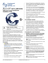
2.5 Mounting
Protect the meter from temperatures below -40°C (-40°F) or above 80°C (176°F), excessive
moisture, dust, salt spray, or other contamination, using a NEMA rated enclosure if necessary. The
meter requires an environment no worse than pollution degree 2 (normally only non-conductive
pollution; occasionally, a temporary conductivity caused by condensation). The meter may be
installed in any orientation.
153 mm (6.02 in)
38 mm (1.50 in) High
Ø
9.8 mm (0.386 in)
Ø
5.1 mm (0.200 in)
85.1 mm (3.35 in)
136.6 mm (5.375 in)
Figure 11: WattNode Meter Dimensions (Drawn to Scale)
The WattNode meter has two mounting holes spaced 5.375 inches (137 mm) apart (center to
center). These mounting holes are normally obscured by the detachable screw terminals. Remove
the screw terminals by pulling outward while rocking from end to end. The meter or Figure 11 may
be used as a template to mark mounting hole positions, but do not drill the holes with the meter
in the mounting position because the drill may damage the connectors and leave drill shavings in
the connectors.
You may mount the meter with the supplied #8 self-tapping sheet metal screws using 1/8 inch
pilot hole (3.2 mm). Or you may use hook-and-loop fasteners. If you use screws, avoid over-tight-
ening which can crack the case. If you do not use the supplied screws, the following sizes should
work (bold are preferred); use washers if the screws could pull through the mounting holes
Table 2: Mounting Screws
Screw Style U.S.A. UTS Sizes Metric Sizes
Pan Head or Round Head #6, #8, #10 M3.5, M4, M5
Truss Head #6, #8 M3.5, M4
Hex Washer Head (integrated washer) #6, #8 M3.5, M4
Hex Head (add washer) #6, #8, #10 M3.5, M4, M5

20 Installation
2.6 Selecting Current Transformers
The WND-series meters can handle a very wide range of current signals, from less than 1% of
rated current to over 200%, while maintaining high accuracy. Most modern CTs, with the excep-
tion of some lower-cost models using silicon-iron cores, are also accurate over a wide range,
commonly from 1% to 120% of rated current. This allows flexibility in selecting the CT rated amps.
The rated full-scale current of the CTs should generally fall in the range between the highest typical
current and the rated current for the circuit being monitored. For example, if you are monitoring a
motor on a 100 amp circuit and the motor normally draws between 30 and 50 amps, you would
be fine using a 50 amp or 100 amp CT.
Take care that the maximum allowable current for the CT can not be exceeded without tripping a
circuit breaker or fuse.
For revenue accuracy, use accuracy class 0.3 or 0.2 current transformers to achieve a 0.5%
system accuracy or class 0.5 or 0.6 CTs for a 1.0% system accuracy; other CTs are less accurate
and may not provide revenue accuracy. Contact sales for more information on appropriate CTs.
We only offer CTs that measure AC current, not DC current. Significant DC current can saturate
the CT magnetic core, reducing the AC accuracy. Most loads only have AC current, but some rare
loads draw DC current, which can cause measurement errors. See our website for more informa-
tion: https://ctlsys.com/s/dc-half-wave-rectified/.
CTs can measure lower currents than they were designed for by passing the conductor through
the CT more than once. For example, to measure currents up to 1 amp with a 5 amp CT, loop the
conductor through the CT five times. The CT is now effectively a 1 amp CT instead of a 5 amp CT.
The effective current rating of the CT is the labeled rating divided by the number of times that the
wire passes through the CT.
With voltage output CTs, you may connect the outputs of CTs of the same model in parallel. This
is useful when monitoring services with two or three large conductors (say an 800 amp service
with two 500 kcmil conductors), because it allows the use of smaller, less expensive CTs. It is also
useful if you wish to combine two or three circuits together for monitoring with one meter. When
paralleling CTs, the effective rated amps is the sum of the rated amps of the CTs being connected
in parallel. For more information, see https://ctlsys.com/s/parallel-cts/.
If you are using the meter elements of the WattNode (VA, VB, and VC) to measure different circuits,
you can use CTs with different rated current on the different inputs. Instead of setting one CtAmps
value for all CTs, you can use different values for each input: CtAmps1, CtAmps2, and CtAmps3.
2.6.1 Approved Current Transformers
The WattNode meter may be used with the following current transformers:
●UL Listed to UL 2808, CSA 61010-2-30 (XOBA/XOBA7), 600 V rated, 0.333 Vac output. This
includes, but is not limited to the following:
ACTL-0750-xxx
ACTL-1250-xxx
CTML-0350-xxx
CTBL-WxL-xxxx
TCL-B-xxx
●UL Listed to UL 2808 (XOBA/XOBA7), 600 V, 40 mA output. The meter must be factory
configured to use milliamp output CTs: contact CCS for details.
TCL-B-100/40mA
●The following UL Recognized CTs. UL Recognized CTs are not for use in panelboards.
ACT-0750-xxx
CTL-1250-xxx
CTM-0360-xxx
CTS-0750-xxx
CTS-1250-xxx
CTS-2000-xxxx
CTB-WxL-xxxx
CTT-0300-xxx
CTT-0500-xxx
CTT-0750-xxx
CTT-1000-xxx
CTT-1250-xxx
CTRC-yyyyy-xxxx
/