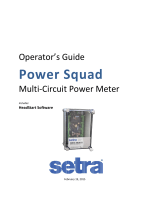
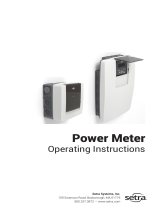
Setra Systems Power Patrol Operating instructions

Category
Networking
Type
Operating instructions
i
Operator’s Guide
Power Patrol
Power Meter
Includes:
Power Patrol
and
HeadStart 4.0 Software
February 19, 2015
Setra Systems, Inc. | 159 Swanson Rd. | Boxborough, MA 01719 USA
Phone 978.263.1400 | Fax 978.264.0292 | www.setra.com
ii
Table of Contents
INTRODUCTION .......................................................................................................................... 1
The Power Patrol Power Meter ............................................................................................................... 1
Power Patrol Meter Safety Summary and Specifications ........................................................................ 1
Symbols on Equipment ............................................................................................................................ 2
Power Patrol Résumé de Sécurité et Spécifications ................................................................................ 4
Symboles des Equipements ..................................................................................................................... 4
Power Patrol Meter Technical Specifications .......................................................................................... 6
FIELD INSTALLATION .................................................................................................................... 8
Mounting a Power Patrol Meter .............................................................................................................. 8
Wiring Connections on a Power Patrol Meter ......................................................................................... 8
Wiring CTs ................................................................................................................................................ 9
CT Wire Lead Polarity .........................................................................................................................................9
Connecting a Communication Cable...................................................................................................... 10
Connecting via a USB Cable Adapter ................................................................................................................10
Connecting via a RS-485 Adapter .....................................................................................................................10
Installing the RS-485 Adapter to a Computer ..................................................................................................11
Connecting via an Ethernet Cable ....................................................................................................................12
Powering the Power Patrol
Meter ......................................................................................................... 12
Power Patrol Single-Phase Connections ..........................................................................................................12
COMCommunications LED ................................................................................................................. 13
Power Patrol (Serial & Ethernet Communication) ...........................................................................................14
Phase Verification .................................................................................................................................. 14
Verifying the Power Patrol Meter Setup Using the LEDs .................................................................................14
Phase Verification Error Table ..........................................................................................................................15
Power Patrol Meter Diagram ................................................................................................................. 16
COMMUNICATING WITH A POWER PATROL METER ........................................................................... 17
Setting the Network Address Switches .................................................................................................. 18
Installing the HeadStart Software and Communicating with the Power Patrol Meter ......................... 19
Communication Setup ......................................................................................................................................19
About IP Addresses ..........................................................................................................................................22
Connecting the Ports ........................................................................................................................................24
Establishing Communication Protocol ................................................................................................... 24
Using HeadStart Software...................................................................................................................... 25
HeadStart Screens ............................................................................................................................................25
Communication and Status Messages .............................................................................................................25
HeadStart Command Buttons ..........................................................................................................................25
iii
Communications .................................................................................................................................... 26
Setting USB Communication Parameters .........................................................................................................26
Setting Serial Communication Parameters ......................................................................................................27
Setting Ethernet Communication Parameters .................................................................................................28
Communication Error .......................................................................................................................................30
Meter Setup ........................................................................................................................................... 31
Entering Wiring Information for an Element ...................................................................................................32
Comms. Setup ........................................................................................................................................ 33
Real-Time Values ................................................................................................................................... 33
Using Real-Time Values to Verify Setup ...........................................................................................................34
Read/Write RegistersRead/Set Objects ............................................................................................. 35
Resetting BACnet Objects/Modbus Registers ..................................................................................................36
Sync Registers...................................................................................................................................................36
Firmware ................................................................................................................................................ 37
SECTION IVALL THINGS MODBUS.............................................................................................. 38
Modbus Data ScalingInterpreting the Power Patrol Registers .....................................................................38
Selecting a Scalar ..............................................................................................................................................39
Examples Using a Data Scalar ...........................................................................................................................39
Values Requiring Two Registers .......................................................................................................................40
Configuration Registers ....................................................................................................................................40
Pulse Output/Input Registers ...........................................................................................................................41
Absolute/Net Value Measurement Registers ..................................................................................................42
Positive Power/Energy Measurement Registers ..............................................................................................46
Negative Power/Energy Measurement Registers ............................................................................................50
Protocol Commands .........................................................................................................................................55
iv
SECTION VALL THINGS BACNET ............................................................................................... 59
Configuration Objects ......................................................................................................................................59
Pulse Output/Input Objects .............................................................................................................................60
Absolute/Net Value Measurement Objects .....................................................................................................60
Positive Power/Energy Measurement Objects ................................................................................................63
Negative Power/Energy Measurement Objects ...............................................................................................64
APPENDICES ............................................................................................................................ 65
Appendix APower Patrol Meter Wiring Diagrams ............................................................................. 65
Power Patrol Plus Wiring Diagrams..................................................................................................................66
Appendix BConnecting to a Network ................................................................................................. 69
Communication Protocol .................................................................................................................................69
Daisy Chain Layout for RS-485 Network ...........................................................................................................69
Networking Using the BACnet/Modbus Protocol ............................................................................................69
Appendix CThe Power Patrol Optional Visual Display ....................................................................... 70
Appendix DVERIS H8035/H8036 Emulation ....................................................................................... 72
VERIS Modbus Integer Registers ......................................................................................................................73
VERIS Multipliers ..............................................................................................................................................74
VERIS Modbus Floating Point Registers ...........................................................................................................76
Appendix EConversion Table.............................................................................................................. 79
Decimal to Hexadecimal Conversion Table ......................................................................................................79
Appendix FTroubleshooting ............................................................................................................... 81
Troubleshooting Communication Issues ..........................................................................................................81
FREQUENTLY ASKED QUESTIONS .................................................................................................. 83
GLOSSARY .............................................................................................................................. 85
1
INTRODUCTION
The Power Patrol meter monitors the voltage, current, power, energy, and many other electrical
parameters on single- and three-phase electrical systems. A Power Patrol meter uses direct connections
to each phase of the voltage, and uses current transformers or Rogowski coils to monitor each phase of
the current. Information on energy use, demand, power factor, line frequency, and more are derived
from the voltage and current inputs.
The communications interface to the meter is an USB communication, or RS-485 serial/Ethernet
connection that uses the BACnet Master Slave Token Passing (MS/TP) protocol or Modbus protocol for
sending commands and retrieving data. A separate remote terminal unit (RTU), Data Logger, or Building
Management and Control System is usually connected to the Power Patrol to provide data recording
and trend logging plus a human interface or display.
POWER PATROL
The Power Patrol is light-weight and compact enough to
mount within an electrical panel. It is typically used for
long-term monitoring of electrical systems.
Up to 127 Power Patrol meters may be connected to a
single BACnet client for monitoring and recording power
usage at multiple locations within a single site. Up to 247
meters may be connected to Modbus.
There is a configurable digital pulse output port on the
Power Patrol that can be used to output kWh, kVARh, or kVAh pulses to external devices, or to toggle on
and off to control a remote device or relay.
Power Patrol Optional Digital
Display
An optional visual display is available on the Power Patrol which cycles through meter information and
real-time values of Volts, Amps, KW, KVA, KVAR, etc. See Appendix.
Power Patrol Meter Safety Summary and Specifications
This general safety information is to
be used by both the Power Meter
operator and servicing personnel.
Setra Systems, Inc. assumes no
liability for user’s failure to comply
with these safety guidelines.
PS3037-X-X
These items conform to the
following:
Conforms to UL Std 61010-1, 3rd
Edition & IEC 61010-2-030, 1
st
Edition
Certified to CSA Std C22.2 No.
61010-1, 3rd Edition
2
The Power Patrol is an over-voltage Category III device. Use approved rubber gloves with mechanical protection and
goggles when operating the device.
CAUTION: THIS METER MAY CONTAIN LIFE THREATENING VOLTAGES. QUALIFIED PERSONNEL MUST DISCONNECT
ALL HIGH VOLTAGE WIRING BEFORE USING OR SERVICING THE METER.
Symbols on Equipment
3
MAINTENANCE
There is no required maintenance with the Power Patrol. Abide by the following items:
Cleaning: No cleaning agents, including water, should be used on the Power Patrol.
Battery Life: (If equipped) The lithium battery is only used to maintain the date and clock settings during power
failure and has a life expectancy of greater than 10 years. Contact Setra Systems for service.
No accessories are approved for use with the Power Patrol other than those specified in the Setra Systems product
literature and price sheets.
If the power Meter appears damaged or defective, first disconnect all power and sensors. Call or email technical
support for assistance.
Setra Systems, Inc.
159 Swanson Road
Boxborough, MA 01719
Phone: 978-263-1400
www.setra.com
4
Power Patrol Résumé de Sécurité et Spécifications
Cette information de sécurité est
destinée à être utilisée à la fois
par l'opérateur de l'enregistreur
et le personnel de service. Setra
Systems, Inc n'assume aucune
responsabilité pour l'utilisateur
qui ne respecte pas les directives
en matière de sécurité.
PS3037-X-X
Tous les articles sont conformes à
ce qui suit:
Conforme à UL Std 61010-1, 3rd
Edition & IEC 61010-2-030, 1
st
Edition
Certifié CSA Std C22.2 No. 61010-1,
3rd Edition
Le Power Patrol est un appareil de surtension de catégorie III. Utiliser des gants en caoutchouc approuvé avec protection
mécanique et des lunettes lors de l'utilisation de l'appareil.
ATTENTION: CE METER PEUT CONTENIR DE HAUTES TENSIONS QUI PEUVENT ÊTRE DANGEREUSES. UN PERSONNEL
QUALIFIÉ DOIT DÉBRANCHER TOUS LES CÂBLES À HAUTE TENSION AVANT D’UTILISER OU DE RÉPARER
DU METER.
Symboles des Equipements
5
Entretien
Il n'y a aucun entretien requis avec le Power Patrol. Respectez les points suivants:
Nettoyage: Aucun agents de nettoyage, y compris l'eau, doit être utilisé sur le Power Patrol.
Espérance de Vie de la Batterie: La pile au lithium est utilisée uniquement pour maintenir les paramètres de date
et d'heure en cas de coupure de le courant et a une espérance de vie de plus de 10 ans. Contactez DENT
Instruments pour le service.
Pas d'accessoires approuvés pour une utilisation avec le Power Patrol sauf ceux spécifiés par DENT Instruments
dans ses documentations sur les produits et également sur les prix.
Si le compteur semble endommagé ou défectueux, tout d'abord déconnecter le pouvoir de l'appareil. Alors s'il
vous plaît appelez 541.388.4774 ou contacter par courriel l'assistance technique pour obtenir de l'aide.
Setra Systems, Inc.
159 Swanson Road
Boxborough, MA 01719
Phone: 978-263-1400
www.setra.com
6
Power Patrol Meter Technical Specifications
Specification
Description
Service Types
Single Phase, Three Phase-Four Wire (WYE), Three Phase-Three Wire (Delta)
3 Voltage Channels
80-346 Volts AC Line-to-Neutral, 600V Line-to-Line, CAT III
Current Channels
3 channels, 0.525 VAC max, 333 mV CTs, 108 mV Rogowski coils, 0-4,700+ Amps
depending on current transducer
Maximum Current Input
158% of current transducer rating (mv CTs) to maintain accuracy. Measure up to 4000
Amps Power Flex Rogowski Coil
Measurement Type
True RMS using high-speed digital signal processing (DSP)
Line Frequency
50/60Hz
Power
From L1 Phase to L2 Phase. 80-600VAC CAT III 50/60Hz SPP: 90mA Max, Non-user
replaceable .5 Amp internal fuse protection
Power Out
Unregulated 5VDC output, 140 mA max
Waveform Sampling
12 kHz
Parameter Update Rate
.5 seconds
Measurements
Volts, Amps, kW, kWh, kVAR, kVARh, kVA, kVAh, Apparent Power Factor (aPF),
Displacement Power Factor (dPF). All parameters for each phase and for system total.
Accuracy
Meter: 0.2% (<0.1% typical) ANSI, C12.20-2010 Class 0.2
Resolution
0.01 Amp, 0.1 Volt, 0.01 watt, 0.01 VAR, 0.01 VA, 0.01 Power Factor depending on
scalar setting
Indicators
Bi-color LEDs (red and green): 1 LED to indicate communication, 3 LEDs for correct
phasing (Green when voltage and current on the same phase; Red when incorrectly
wired.) Pulse output LED, Power On LED
Pulse Output
Open Collector, Optically Isolated , 5mA max current, 30V max open voltage
Communication
Direct
User Selectable Modbus RTU or TCP; BACnet Master Slave Token Passing protocol
(MS/TP) RS-485 or IP (Ethernet)
Serial Meters
Max Communication
Length
1200 meters with Data Range of 100K bits/second or less
Communication Rate
(baud)
Modbus: 9600 (Default), 19200, 38400, 57600, 76800, 115200
BACnet: 9600, 19200, 38400, 76,800 (Default)
Data Bits
8
Parity
None, Even, Odd
Stop Bit
2, 1
Data Formats
BACnet IP, BACnet MS/TP, Modbus TCP, Modbus RTU
Mechanical
Operating Temperature
-7 to + 60 C (-20 to 140 F)
Humidity
5% to 95% non-condensing
7
Specification
Description
Enclosure
ABS plastic, 94-V0 flammability rating
Weight
366.5 g (12.92 oz, 0.808 lbs)
Dimensions
24.2 x 8.5 x 4.0 cm (9.5” x 3.3 x 1.6”)
Ingress Protection (IP) Rating
20
Accessories
Mounting Rail
Compatible with a TS35/7 DIN Rail Channel
Digital Display
An optional 2 x 16 character display which auto-cycles between informational screens
every 2-3 seconds, with real-time values updated every second.
HeadStart Minimum System Requirements
Operating System
Windows® 7 (32 or 64 bit), Windows® 8 Pro, Vista (32 or 64 bit), XP
Communications Port
One USB port or serial port
Hard Drive
50 MB minimum available
Processor
Pentium Class 1 GHz or more recommended
Safety
Serial/Ethernet Meters
The following are UL listed:
SPP-E-N, SPP-E-D, SPP-S-N, SPP-S-D
Power Patrol Meter
Conforms to UL Std 61010-1, 3rd Edition & IEC 61010-2-030, 1st Edition
Certified to CSA Std C22.2 No. 61010-1, 3rd Edition
Table I-1: Technical Specifications
8
FIELD INSTALLATION
Mounting a Power Patrol Meter
The Power Patrol
meter must be installed in an approved electrical panel or enclosure using proper
installation practices according to the local electrical codes.
To mount the Power Patrol, use the two tabs provided at both ends of the case. Securely mount
the Power Patrol near a dedicated circuit disconnect breaker.
Figure I-1: Power Patrol mounting tabas
Wiring Connections on a Power Patrol Meter
High voltage MAY BE PRESENT. Risk of electric shock. Life threatening voltages may be present.
Qualified personnel only.
Haute tension peut être présente. Risque de choc électrique. Tensions dangereuses peuvent
être présentes. Personnel qualifié uniquement.
The Power Patrol meter has the following connections:
USB port for powering the meter and communicating during setup, a three-wire connector for
the RS-485 BACnet/Modbus link, and an Ethernet port (optional).
Digital output ports. The port can be used to output kWh, kVARh, or kVAh pulses to external
devices, or to toggle on and off to control a remote device or relay.
Three CT inputs.
Four voltage connections. Voltage leads are customer supplied. PowerScout meters are self-
powered from L1 and L2.
WARNING! Remove the meter from all sources of voltage before mounting.
Mounting tab,
located on each
end of meter case
9
Completing the Field Installation
Follow these steps to complete the field installation of your Power Patrol meter:
Connect whatever communications cable you are using to the building network.
Connect your pulse output, if used. The port can be used to output kWh, kVARh, or kVAh pulses
to external devices, or to toggle on and off to control a remote device or relay. See Using the
Pulse Output Port Function.
Connect the CTs. See Wiring CTs.
Connect the voltage and power the meter. See Connecting Voltage.
Using the Pulse Output Port Function
Pulse output is used to generate pulses for external devices such as data loggers that can accept pulses
but do not have BACnet or Modbus capability. The Power Patrol can generate pulses based on
accumulated value(s) such as system kWh, system kVARh, and system kVAh. When a pulse is generated
by the meter, the orange LEDs will briefly flash, otherwise they will remain dark.
When in Modbus, the pulse output is scaled by the Modbus data scalar register 44602. When in BACnet,
the pulse output is scaled by the CT Pulse Scalar object 12030. The pulse scalar table is the same as the
Modbus data scalar table. For example, when the data scalar is set to 3, each pulse will represent .1
kWh, .1kVAh and .1kVARh.
CT Inputs
Ethernet
Port
RS-485
Port
Digital
Output Port
Voltage Connections
USB Port
10
Data Scalar
Pulse Scalar Value
kWh
kVAh
kVARh
0
.00001
.00001
.00001
1
.001
.001
.001
2
.01
.01
.01
3
.1
.1
.1
4
1
1
1
5
10
10
10
≥6
100
100
100
Table II-1: Pulse Scalar Values
For system pulse output:
kWh pulse outputwrite 44001 into the pulse output configuration object.
kVAh pulse outputwrite 44011 into the pulse output configuration object.
kVARh pulse outputwrite 44008 into the pulse output configuration object.
11
MODBUS OUTPUT PORT REGISTERS
Refer to the following two tables to configure the Power Patrol output ports when using the Modbus
protocol.
Modbus
Register
Offset
Register Name
Detailed Description
44402
4401/5301
Port 1 output control
when used as an on/off
open/closed switch
0 = output LOW (closed)
1 = output HIGH (open) [default]
Register 45110 must = 0 to use
45110
5109/5309
Digital Port 1
Configuration
Turns pulses on/off
0 = No pulses, Port may be used as an
on/off
open/closed switch
44001 = System kWh pulses
44008 = System kVARh pulses
44011 = System kVAh pulses
45111
5110/5310
Port 1 pulse output relay
type
0 = normally open (HIGH)
1 = normally closed (LOW)
Table II-2: Modbus Digital Port Pulse Output
BACNET OUTPUT PORT OBJECTS
Refer to the following two tables to configure the Power Patrol output ports when using the BACnet
protocol.
SPP
Object
Identifier
Name
Detailed Description
13020
Port 1 output control when used as an
on/offopen/closed switch
0 = output LOW (closed) 1 = output HIGH
(open) [default]
Object 13100 present value must = 0 to use
13100
Digital Port 1 Configuration
Turns pulses on/off
0 = No pulses, Port may be used as an
on/off
open/closed switch
44001 = System kWh pulses
44008 = System kVARh pulses
44011 = System kVAh pulses
13110
Port 1 pulse output relay type
0 = normally open (HIGH)
1 = normally closed (LOW)
Table II-3: BACnet Digital Port 1 Pulse Output
12
Wiring CTs
1) Insert the CT wires into the connector/s. See the following CT wire lead polarity table for the correct
wiring configuration.
CT WIRE LEAD POLARITY
CT Type
CT
Lead +
CT Lead
-
Shield
Power Flex (Rogowski coil)*
Red
Black
Shield
Wire
Split Core CT mV (SCP, SCM
series)
White
Black
Table II-4: CT Polarity
2) Attach the CT connectors onto the Power Patrol connections labeled CT 1, CT 2 and CT 3.
3) Place the CTs on the phase wires of the load to be monitored and corresponding to the phase of the
voltage leads. The CT labeled CT 1 must be placed on L1 phase voltage wire, CT 2 must be on the L2
voltage and CT 3 on the L3 voltage. Refer to Phase Verificatio later in this section for information
about the CT LEDs and verifying the CT installation.
NOTE: The directionality for Rogowski Coils is the arrow on the label pointing toward the load.
* Power Flex Rogowski Coils have a shield wire which must be connected to the meter. This reduces
interference and improves accuracy of the CT.
Connecting a Communication Cable
High voltage MAY BE PRESENT. Risk of electric shock. Life threatening voltages may be present.
Qualified personnel only.
Haute tension peut être présente. Risque de choc électrique. Tensions dangereuses peuvent
être présentes. Personnel qualifié uniquement.
Communication between a Power Patrol meter and a logger or computer is established with an USB
cable, a serial RS-485 adapter or an Ethernet connection. A serial connection (RS-485) is limited in speed
while a parallel connection (Ethernet) or USB connection is much faster.
NOTE: Configuration of Power Patrol meter can be completed prior to field installation by powering
device via computer and USB cable using HeadStart software.
CONNECTING VIA A USB CABLE
13
Connect one end of USB cable into the Power Patrol and the other end into your computer. To begin
communicating via an USB cable you must first set it up with HeadStart Software. See USB Connection in
the Communicating with a Power Patrol Meter section.
CONNECTING VIA A RS-485 ADAPTER
To complete the connection between the Power Patrol meter and the computer, the three wires coming
from the RS-485 adapter are plugged into the Power Patrol.
Insert each white ferrule into the appropriate RS-485 connection on the Power Patrol. The red wire
inserts in (+), the black wire in (-) and the green wire in GND, Figure II-1.
Verify that the dip switches on the back of the RS-485 adapter are set to: RS-485, Echo Off, 2 Wire, 2
Wire as shown in Figure II-2.
The adapter is ready to be connected to the Power Patrol meter.
INSTALLING THE RS-485 ADAPTER
TO A COMPUTER
Installation of an RS-485 adapter and HeadStart
software can be completed and tested with a meter
prior to the field installation.
4) Insert one end of a USB cable into the RS-485 adapter and the other end into a USB port on the
computer.
5) Insert the CD that came with the RS-485 adapter into your computer.
6) The Found New Hardware Wizard window appears.
Figure II-2: Dip switches on back
of RS-485 Adapter
Figure II-1: RS-485 Adapter
14
The window states “This wizard helps you install software for: Model USOPTL4,” and asks “What do
you want the wizard to do?”
7) Select Install the software automatically and click Next.
8) Click Finish when the installation is complete.
9) Remove the CD from your computer.
15
CONNECTING VIA AN ETHERNET CABLE
Connect one end of the Ethernet cable into the Power Patrol and the other end into your computer. To
begin communicating via an Ethernet cable you must first set it with HeadStart software. See Ethernet
(TCP/IP) Connection in the Communicating with a Power Patrol Meter section.
Powering the Power Patrol
Meter
The Power Patrol meter can be powered through USB cable and computer prior to field installation for
configuration purposes.
For field installation, connect the Power Patrol meter 14
AWG THHN Minimum 600VAC rating (or equivalent in
order to maintain 600VAC safety rating of the device)
voltage leads as close as possible to a building-installed,
dedicated circuit disconnect breaker. Mark the breaker
as the “disconnect for the Power Patrol. Refer to the
wiring diagrams in the Appendix for specifics of the
wiring connections.
Follow local electrical codes during this installation.
Figure II-3: Voltage leads into circuit breaker
The Power Patrol meter is self-powered from the L1 and L2 lines. When 80600VAC or DC is placed
across the L1 and L2 wires, the three phasing LEDs begin to flash in sequence.
POWER PATROL SINGLE-PHASE CONNECTIONS
The Power Patrol meter can be used to monitor single-phase loads. There are several guidelines to keep
in mind about this type of connection:
1) The Power Patrol is powered from a potential between L1 and L2. This can be phase-to-phase (230V)
or phase-to-neutral (115V). With a single-phase 230V panel, the L1 and L2 voltage leads are
connected between the L1 and L2 voltage sources. With a 115V circuit, the L1 voltage lead is
connected to the L1 “hot lead,” and the L2 voltage lead is connected to neutral.
2) Each CT must be paired with the correct voltage source. The current and voltage need to be in-
phase for accurate measurements. For instance, CT 1 would monitor branch circuit supplied by
voltage source L1, and so on.
3) The neutral must be connected because the Power Patrol uses line-to-neutral measurements for all
calculations.
16
A Typical 230V Single-Phase Panel
Setup (US Wire Colors)
Connect the Black L1 voltage lead to Voltage L1, Red L2 voltage lead to L2 voltage, White Neutral voltage
lead to neutral. CT1 would monitor L1 loads and CT2 would monitor L2 loads. Based on the above
guidelines, CT3 can be used if the Blue L3 voltage lead is connected to either L1 or L2. As long as voltage
lead L3 and CT3 are in-phase, the Power Patrol meter will provide correct kW readings. If the Blue L3
voltage lead was connected to L2 voltage source, then CT3 could monitor any L2 branch circuit. Or, if the
Blue L3 voltage lead was connected to L1 voltage source, then CT3 could monitor any L1 branch circuit.
A Typical 115V Single-Phase Panel
Setup
Connect the Black L1 voltage lead to Voltage L1 (hot), Red L2 voltage lead to Neutral, and White N
voltage lead to neutral. CT1 would monitor the L1 load. CT3 can be used if the Blue L3 voltage lead is
connected to L1. CT3 could then monitor any L1 branch circuit.
System Values
System values are the sum of L1 + L2 + L3 measurements. System values may not be meaningful since
two different devices or loads can be monitored by a single Power Patrol element.
When paired with the right voltage phase, each CT provides individual kW/kWh readings for that CT
channel.
COMCommunications LED
The Power Patrol COM LEDs signal the following communication information.
POWER PATROL (SERIAL COMMUNICATION ONLY)
BACnet
Modbus
Description
Steady Green
Steady Green
Power is applied to the meter.
Flashing Green
Flashing Green
The meter is communicating.
Steady Red
Communications failure, or talking with BACnet while the meter is in
Modbus mode.
Flashing Red
The meter is receiving communication on the bus for a meter at
another address.
Table II-5: Serial COM LED Signals
  • Page 1 1
  • Page 2 2
  • Page 3 3
  • Page 4 4
  • Page 5 5
  • Page 6 6
  • Page 7 7
  • Page 8 8
  • Page 9 9
  • Page 10 10
  • Page 11 11
  • Page 12 12
  • Page 13 13
  • Page 14 14
  • Page 15 15
  • Page 16 16
  • Page 17 17
  • Page 18 18
  • Page 19 19
  • Page 20 20
  • Page 21 21
  • Page 22 22
  • Page 23 23
  • Page 24 24
  • Page 25 25
  • Page 26 26
  • Page 27 27
  • Page 28 28
  • Page 29 29
  • Page 30 30
  • Page 31 31
  • Page 32 32
  • Page 33 33
  • Page 34 34
  • Page 35 35
  • Page 36 36
  • Page 37 37
  • Page 38 38
  • Page 39 39
  • Page 40 40
  • Page 41 41
  • Page 42 42
  • Page 43 43
  • Page 44 44
  • Page 45 45
  • Page 46 46
  • Page 47 47
  • Page 48 48
  • Page 49 49
  • Page 50 50
  • Page 51 51
  • Page 52 52
  • Page 53 53
  • Page 54 54
  • Page 55 55
  • Page 56 56
  • Page 57 57
  • Page 58 58
  • Page 59 59
  • Page 60 60
  • Page 61 61
  • Page 62 62
  • Page 63 63
  • Page 64 64
  • Page 65 65
  • Page 66 66
  • Page 67 67
  • Page 68 68
  • Page 69 69
  • Page 70 70
  • Page 71 71
  • Page 72 72
  • Page 73 73
  • Page 74 74
  • Page 75 75
  • Page 76 76
  • Page 77 77
  • Page 78 78
  • Page 79 79
  • Page 80 80
  • Page 81 81
  • Page 82 82
  • Page 83 83
  • Page 84 84
  • Page 85 85
  • Page 86 86
  • Page 87 87
  • Page 88 88
  • Page 89 89
  • Page 90 90
  • Page 91 91

Setra Systems Power Patrol Operating instructions

Category
Networking
Type
Operating instructions

Ask a question and I''ll find the answer in the document

Finding information in a document is now easier with AI