12400 Earl Jones Way, Louisville, KY 40299
(800) 626-1126 | www.rev-a-shelf.com
INSTALLATION
INSTRUCTIONS
SOFT-CLOSE
MIXER LIFT DAMPENER
12400 Earl Jones Way, Louisville, KY 40299
(800) 626-1126 | www.rev-a-shelf.com

INSTALLATION
INSTRUCTIONS
SOFT-CLOSE
MIXER LIFT DAMPENER
12400 Earl Jones Way, Louisville, KY 40299
(800) 626-1126 | www.rev-a-shelf.com
TOOLS REQUIRED:
ESTIMATED ASSEMBLY
TIME:
15 MIN
CARE AND MAINTENANCE:
CLEAN WITH A DAMP CLOTH
AND WIPE PARTS DRY.
1/2”
Description QTY
A
Dampeners
2
B
Ball Studs
4
C
Lock Washers
4
D
Retaining Clips
4
A
B C D
NOTE: IT IS VERY IMPORTANT THAT YOU FOLLOW THESE DIRECTIONS CAREFULLY. THE FIXED
CYLINDER END OF THE DAMPENER MUST BE INSTALLED AT THE TOP LOCATION FOR
LUBRICATION OF THE DAMPENER TO MAINTAIN PROPER FUNCTION. THE RETAINING CLIPS
MUST BE USED FOR SAFE OPERATION OF THE ASSEMBLY.
1) Put (2) lock washers on the threaded end of
(2) ball studs, screw into the arm assembly of the
mixer lift and then tighten with a ½” wrench.
2) Pull the ends of the dampener apart
about ½”. (This will be slightly dicult due
to the dampening eect of the cylinder.)
*FOR EXISTING MIXER LIFT, GO TO PAGE 3.
1
I-MLHDSC-TRI-0415

3) Insert the xed (cylinder) end of the dampener
onto the top ball stud (on arm with rounded back
end) and press until it snaps on.
4) Rotate the movable (shaft) end of the dampener
to the other ball stud and snap on.
5) Insert (2) retaining clips into (2) ball connectors by sliding the tall end into the bottom hole
of the connector, pushing it through top hole and rotating to snap on at the bottom of the
ball. (If the clip is dicult to go into the hole, you may have to turn the ball connector to center
it on the ball stud)
6) Repeat steps 1-5 for the other arm assembly.
2
I-MLHDSC-TRI-0415

INSTALLATION
INSTRUCTIONS
SOFT-CLOSE
MIXER LIFT DAMPENER
12400 Earl Jones Way, Louisville, KY 40299
(800) 626-1126 | www.rev-a-shelf.com
FOR EXISTING MIXER LIFT
ESTIMATED ASSEMBLY
TIME:
30 MIN
CARE AND MAINTENANCE:
CLEAN WITH A DAMP CLOTH
AND WIPE PARTS DRY.
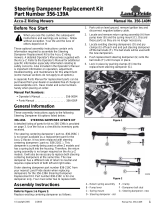
DRILLANDTAP
Top Arm
Bottom Arm
Warning: It is recommended that this procedure be done by a skilled machinist. The locations of
the holes are critical and the tolerance on their location is +/- 1/32”. The holes must be tapped
exactly perpendicular to the arm.
To install dampener onto an existing Mixer Lift, you have to drill and tap (2) 5/16”-18 holes on the arms.
1) On the top arm (rounded end), measure 3-11/32” from bottom and place mark at the center of arm.
2) On the bottom arm (at end), measure 7-5/8” from bottom and place mark at the center of arm.
3) With the unit in the open position, drill 17/64” diameter hole in the top arm and tap with 5/16”-18 tap.
4) Close the unit and drill 17/64” diameter hole in the bottom arm and tap with 5/16”-18 tap.
5) Follow steps 1-4 on other arm assembly.
6) Follow directions on pages 1-2 to install dampener kit.
17/64”
TOOLS REQUIRED:
5/16”-18
3
(OPEN POSITION)
I-MLHDSC-TRI-0415

INSTRUCTIONS D’INSTALLATION
INSTRUCCIONES DE INSTALACIÓN
FERMETURE EN DOUCEUR AMORTISSEUR
DU SYSTÈME ESCAMOTABLE DU MIXEUR
CIERRE SUAVE CUIDADO Y MANTENIMIENTO
12400 Earl Jones Way, Louisville, KY 40299
(800) 626-1126 | www.rev-a-shelf.com
OUTILS:
HERRAMIENTAS:
DUREE:
TIEMPO:
15 MIN
ENTRETIEN ET MAINTENANCE
CUIDADO Y MANTENIMIENTO:
NETTOYEZ AVEC UN LINGE HUMIDE ET
ESSUYEZ LES PIÈCES POUR LES SÉCHER
COMPLÈTEMENT.
LIMPIE LAS PARTES CON UN PAÑO
HÚMEDO Y SEQUE COMPLETAMENTE
Clé de 1,27cm (½”)
Llave de 1/2”
Description
Descripción
QTY
A
Amortisseurs
Amortiguadores
2
B
Goujons sphériques
Postes con bola
4
C
Rondelles de verrouillage
rondanas de seguridad
4
D
Attaches de retenue
clips de retención
4
A
B C D
NOTE: IL EST TRÈS IMPORTANT QUE VOUS SUIVIEZ SOIGNEUSEMENT CES INSTRUCTIONS. L’EXTRÉMITÉ FIXE
(CYLINDRE) DE L’AMORTISSEUR DOIT ÊTRE INSTALLÉE À L’EMPLACEMENT DU HAUT POUR QUE LA LUBRIFICA-
TION DE L’AMORTISSEUR MAINTIENNE UN FONCTIONNEMENT CORRECT. LES ATTACHES DE RETENUE DOIVENT
ÊTRE UTILISÉES POUR UN FONCTIONNEMENT SÛR DE L’ASSEMBLAGE.
NOTA: ES MUY IMPORTANTE QUE USTED SIGA CUIDADOSAMENTE ESTAS INSTRUCCIONES. LA PARTE FI
NAL DEL AMORTIGUADOR CILINDRO DEBE ESTAR INSTALADA EN LA UBICACIÓN SUPERIOR PARA LUBRI
CACIÓN DEL AMORTIGUADOR PARA MANTENER UN FUNCIONAMIENTO APROPIADO. LOS CLIPS DE RETÉN
DEBEN SER USADOS PARA SEGURIDAD DEL ENSAMBLADO.
1) Mettez 2 rondelles de blocage sur l’extrémité letée des
2 goujons sphériques, vissez dans l’assemblage du bras du
système escamotable du mixeur et puis serrez avec une clé
de 1,27cm (½”).
1) Coloque dos rondanas de seguridad en la parte roscada
de dos postes con bola, atornille dentro del brazo de ens-
amble de la palanca de la batidora y luego apriete con una
llave de 1/2”. Utilice el paso 1 del PDF.
2) Tirez sur les extrémités de l’amortisseur
d’environ 1,27cm (½”). (Ceci sera un peu dif-
cile en raison de l’eet d’amortissement du
cylindre.)
2) Jale las partes nales del amortiguador cerca de
1/2”. Esto puede ser un poco difícil debido al efecto
del cilindro del amortiguador. Utilice el paso 2 del PDF,
usted tendrá que insertar una echa enseñando como
jalar el eje afuera del cilindro.
*PARA PALANCA EXISTENTE DE BATIDORA, IR A LA PÁGINA 3.
*POUR UN SYSTÈME ESCAMOTABLE DE MIXEUR EXISTANT, ALLER À LA PAGE 3.
1
I-MLHDSC-TRI-0415
Page is loading ...
Page is loading ...
Page is loading ...
/