
INSTALLATION INSTRUCTIONS: REV-A-MOTION™ KIT FOR TOP MOUNT WASTE CONTAINERS
12400 Earl Jones Way
Louisville, KY 40299
rev-a-shelf.com
Customer Service: 800-626-1126
REV-A-MOTION™ KIT FOR TOP MOUNT WASTE CONTAINERS
TOOLS REQUIRED:
60 MIN
ESTIMATED ASSEMBLY TIME:
CARE AND MAINTENANCE:
Clean with a damp cloth and
wipe parts dry.
I-WCTMRAM-1217
#2
NOTE:
THIS PRODUCT HAS 3 CONFIGURATIONS THAT HAVE SEPARATE INSTALLATION
REQUIREMENTS. DETERMINE WHERE TO BEGIN YOUR INSTRUCTIONS BELOW:
FACE FRAME CABINETS – BEGIN ON PAGE 2
• OVERLAY DOORS
• INSET DOORS
FRAMELESS CABINETS – BEGIN ON PAGE 5
• OVERLAY DOORS
#2
PH
8
mm

Customer Service: 800-626-1126 | rev-a-shelf.com
2
Remove the gas spring from the
unit by removing the retainer clip
from each of the ball sockets and
popping the spring ends from the
ball studs (See Fig 1).
PREPARING UNIT
FOR INSTALLATION
STEP 1
ATTACHING THE REAR
MOUNTING STRAP
STEP 3
NOTE: If rear cabinet wall is
less than 1/2” thick, the use of
a furring strip may be necessary
(See Fig 3.1).
Position the rear strap assembly
as shown in Fig 3.2. Be sure it’s
centered on the back wall and
elevated so the center slot of each
rear socket is positioned 17-15/16”
(50 qt. version) or 12-7/8” (35 qt.
version) from the cabinet oor
(See Fig 3.3).
Fasten the rear strap assembly
to the rear cabinet wall using the
(4) #8 x 5/8” pan head screws
provided. We recommend starting
with (2) screws in the center slots in
case adjustments are necessary.
NOTE: Make sure to adjust
the rear bracket dimensions
accordingly if you are using
system holes
FIGURE 1
FIGURE 3.3FIGURE 3.2FIGURE 3.1
FIGURE 2.2FIGURE 2.1
PUSH TO RELEASE
SLIDE OUT
EXTEND
SLIDE TO
REVEAL
TRIGGER
17-15/16” (50 qt.)
12-7/8” (35 qt.)
Face Frame Cabinet Installation
Step 1A Preparing the Unit for installation
Remove the Gas Spring from the unit.
This is done by removing the two retainer clips from each of the ball sockets and then
popping the spring ends from the ball studs. (SEE FIGURE 1A)
Disengage the cabinet members from the unit by pressing the release levers on the 2
slides and pulling them away from the product members. (SEE FIGURE 1A)
Step 2A Attaching Rear Mounting Strap
Fasten the rear strap assembly to the rear cabinet wall using the (4) #8 x 5/8” pan head
screws provided. The CENTER slot of each rear socket should be positioned 17-15/16”
(for 50 qt. frames) or 12-7/8” (for 35 qt. frames) from the floor of the cabinet as shown
in FIGURE 2A. It is best to start with two screws in the center slots in case adjustments
are necessary. Make sure to center the strap assembly left to right according to the
opening of the face frame. (SEE FIG 2A)
Note: If rear of cabinet is thinner than ½”, a furring strip should be used between the
back wall and the mounting strap to ensure the rear mounting strap is properly attached.
Keep in mind the minimum depth required is 21-3/4” and is measured from the back
of the door.
Step 3A Assembling Side Mounting Brackets
For face frame applications, only the product member bracket and the side
mounting bracket are necessary. (SEE FIGURE 3A)
Please refer to Table A for the proper hole alignment. If the table does not
apply to the cabinet in use, the outer slots will provide a fully adjustable
option to fit virtually any opening. Fasten the brackets according to table A
using the M5 nuts, bolts, and washers provided.
Step 4A Attaching Slides to Cabinet
While supporting the front of the side mounting bracket engage the back of the slide
with the rear strap assembly by sliding it into the outer socket of the assembly. The
product member should be pushed into the rear strap assembly until the front of each
product member and each side-mounting bracket is flush with the front of the face
frame. This is a press fit and there will be resistance. (SEE FIGURE 4A)
Continue to support the front of the slide. Do not let it fall as it may damage the rear
strap assembly.
Locate the bottom of the side-mounting bracket 15 ¾” (for 50 qt. frames) or 10-11/16”
(for 35 qt. frames) from the floor of the cabinet. Attach each bracket to the inside of
the face frame using the (3) #6 x 5/8” flat head screws provided. (SEE FIGURE 5A)
Note: it is recommended to pre-drill using a 3/32” drill bit
PROCEED TO STEP 6
FIGURE 2A
FIGURE 5A
CABINET MEMBER
HOLE LOCATION
PRODUCT MEMBER
HOLE LOCATION
MENDING PLATE
HOLE LOCATION
CABINET MEMBER
HOLE LOCATION
PRODUCT MEMBER
HOLE LOCATION
MENDING PLATE
HOLE LOCATION
1.5" Face Frame
C
C
N/A
1.625" Face Frame
B
B
N/A
1.75" Face Frame
A
A
N/A
Frameless with .75" Wall
B
A
2 & 5
Frameless with .708" Wall
B
D
1 & 8
Frameless with .625" Wall
B
B
3 & 6
Shimmed Inset Door 1.5" FF
C
C
N/A
Shimmed Inset Door 1.625" FF
B
B
N/A
Shimmed Inset Door 1.75" FF
A
A
N/A
FIGURE 1A
FIGURE 4A
1-1/2” Face Frame Example
-Product Member Top
-Side Mount Brkt Bottom
INSTALLATION INSTRUCTIONS
For Full Height Top Mount Waste Containers
With Rev-A-Motion
For face frame style cabinets see steps 1A-4A
For frameless style cabinets see steps 1B-5B
For cabinets with inset doors see steps 1C-4C
CENTER
Release the slides from the frame
by extending the slide as shown in
Fig 2.1, revealing the trigger. Push
the trigger as shown in Fig 2.2 to
release the slides.
STEP 2
FACE FRAME CABINET APPLICATION
#2
800-626-1126 | rev-a-shelf.com
2
Pull slides away from wood
frame until they stop. Press the
black lever in the middle of the
slide to the opposite side and
pull slide to disconnect. (It may
take a little force to pull apart.)
See Fig. B
STEP 1
Install rear brackets to the
outer member of the slides
that you just removed. Make
sure the bend is facing the
inside of the slide as shown.
See Fig. C
STEP 2
FIG. C
Measure the distance from the
inside wall of your cabinet to
the opening and record. ((A) in
Fig. D)) You will need this num-
ber for step 6.
STEP 3
FIG. B
I-WCTMBBSC150-0315
INSTALLATION
INSTRUCTIONS
Top Mount Pull-Out Waste Containers
For models: 4WCTM-12BBSCDM1, 4WCTM-15BBSCDM2,
4WCTM-18BBSCDM2, 4WCTM-1550BBSCDM-1
and 4WCTM-2150BBSCDM-2
TOOLS REQUIRED:
ESTIMATED ASSEMBLY
TIME:
45 MIN
CARE AND MAINTENANCE:
CLEAN WITH A DAMP CLOTH
AND WIPE PARTS DRY.
WOVEN BASKET INSTALLATION INSTRUCTIONS
ESTIMATED ASSEMBLY TIME:
20 MIN
CARE AND MAINTENANCE:
Clean basket and wood frame with a damp cloth and wipe parts
dry. Machine wash liner in cold water with like colors.
2409 Plantside Dr., Jeersontown, KY 40299
800.626.1126
www.rev-a-shelf.com
1) Measure the inside cabinet width (ICW) at desired height for wood rails.
2) Measure the width of basket wood frame (BW).
3) Subtract BW from ICW. Divide answer by 2. Subtract 1/16” from answer.
This will give you the dimension needed from bottom of groove to back of wood
rail (ICW-BW) ÷ 2 - 1/16”.
4) Cut wood rails per steps 1-3.
5) Place rst cut rail in cabinet with front of rail against back of face frame (for
frameless cabinets, ush with front of cabinet.) at desired height. Secure the front
hole with proper size screw. (Screws not included due to variant in cabinet wall
thicknesses) (Make sure screw does not go through outside wall of cabinet).
Part list:
NOTE: SCREWS NOT INCLUDED DUETO VARIANT SIZES IN CABINETS
(ICW-BW) ÷ 2 - 1/16”
Desired Height
of Rail
Inside
Cabinet
Width
(ICW)
Basket
Width
(BW)
Bottom of groove
Back of wood rail
8) Install second rail on opposite side of cabinet per steps 5-6 at height
location from step 7.
7) Measure from oor of cabinet to bottom of installed rail.
6) Make sure rail is level, then secure to cabinet with screws at
remaining hole locations.
9) Slide in basket.
I-4WV-TRI-1013
Bottom of
rail to oor of
cabinet
Repeat steps for additional baskets.
Visit our YouTube Channel for an installation video of this product
Youtube.com/REVASHELF nd “Wood Top Mount”
1/16”
12400 Earl Jones Way, Louisville, KY 40299
(800) 626-1126 • www.rev-a-shelf.com
Step1: Install rear bracket to rear of slide.
19” 19”
INSTALLATION INSTRUCTIONS
for Top Mount Pull-Out Waste Containers
INSTRUCCIONES DE INSTALACIÓN
para cestos de basura deslizantes con montaje superior
NOTICE D’INSTALLATION
de la poubelle montée sur glissières supérieures
For models, Para los modelos, Pour les modèles:
4WCTM-12BBSCDM1, 4WCTM-15BBSCDM2,
4WCTM-18BBSCDM2, 4WCTM-1550BBSCDM-1
and 4WCTM-2150BBSCDM-2
Step 2:
Paso 2: Instale la parte delantera de la deslizadera en el bastidor
Étape 2: Monter l’avant de la glissière sur le cadre frontal. Le trou doit se
Step 5: Mount Rear Bracket. Extend the slide rear mounting bracket until it
cabinet wall at rear of slide as it is up front.
tighten. Tighten screw in front
bracket.
Paso 5: Monte el soporte trasero. Extienda el soporte trasero de la
deslizadera hasta que toque atrás (el listón trasero). La parte inferior de
distancia entre la parte posterior de la pared del
soporte de montaje trasero debe ser similar a la
frente. Introduzca el tornillo de montaje en la
el centro del soporte de montaje trasero y
soporte delantero.
Étape 5: Monter le support arrière. Étendre le support de montage arrière
de la glissière jusqu’à ce qu’il touche l’arrière (le tasseau). Le dessous de la
séparant le
support de montage arrière
Placer une vis de montage dans la fente
horizontale du centre du support
de montage arrière et la serrer. Serrer la vis du support avant.
Step 6: Install wood unit (with slides attached) into cabinet, engaging
product member slides into cabinet member slides push unit until it locks
in place.
Paso 6: Instale la pieza de madera (con las deslizaderas instaladas) en
el armario de forma que las deslizaderas en el producto se entren en las
deslizaderas que están en el
armario y empuje hasta que cierren.
Étape 6: Installer l’ensemble en bois (avec les glissières
montées) dans l’armoire en engageant les glissières du produit dans celles
de l’armoire. Pousser sur l’ensemble jusqu’à ce qu’il s’enclenche.
Step 1: Install rear bracket to rear of slide.
Paso 1: Instale el soporte trasero en la parte posterior de la deslizadera.
Étape 1: Attacher le support arrière à l’arrière de la glissière.
STEP 4:
Measure from inside
cabinet wall to inside
face frame (A) distance
should be measured
the same at rear of
cabinet (B).
STEP 6:
Install wood unit (with slides attached) into cabinet,
engaging product member slides into cabinet member
slides, push
unit until it
locks in place.
Now you are
ready to
mount the
door.
STEP 7:
See door mounting instructions on inside.
STEP 5:
Position the slide with front
bracket on the face frame
opening and move it forward
until the self register stop hits the
inside of the face frame opening.
Bottom of slide should be 13 1/2"
from cabinet floor. Install screw in
slotted mounting hole, do not
tighten. Extend the slide rear mounting bracket until it
contacts the rear Furring strip. Bottom of slide should be
13 1/2" from cabinet floor. Rear mounting bracket should
be the same distance from the side cabinet wall at rear of
slide as it is up front. Drive mounting screw in center
horizontal slot of rear mounting bracket, tighten.
Tighten screw in front bracket.
Face Frame
Cabinet Member
Slides
Furring Strips
Product Member Cabinet Member
Self
Register
Stop
Front View
(B)
Step 3: If rear of cabinet is thinner than ½”, install a ½” x 3” wide furring
Paso 3: Si el grosor de la parte trasera del armario es inferior a
13 mm (½ pulg.), instale un listón de
13 x 76 mm (½ x 3 pulg.) de ancho
centrada en la parte trasera y a 36cm
(14 ¼
pulg. - 35 y 27Qt. / 20 ⁄ - 50Qt.) del
Étape 3: Si l’arrière de l’armoire est
moins épais que 13 mm (½ po),
attacher un tasseau de
13mm x 76mm (½ x 3 po) à l’arrière de l’armoire,
centré à 36 cm (14-¼
po. - 33 et 25(L) / 20- ⁄ po. - 47(L)) du fond de l’armoire.
Step 4: Measure from inside cabinet wall to inside face frame (A) distance
should be measured the same at rear of cabinet (B).
Paso 4: La medida de la pared interior del
STEP 1:
Install front bracket to
front side of slide.
STEP 2:
Install rear bracket to
rear of slide.
STEP 3:
Mount slide to cabinet
if rear of cabinet is
thinner then 1/2" install
a 1/2" x 3" wide furring
strip to the back of the
cabinet centered
14 1/4" from floor of
cabinet.
STEP 4:
Measure from inside
cabinet wall to inside
face frame (A) distance
should be measured
the same at rear of
cabinet (B).
STEP 6:
Install wood unit (with slides attached) into cabinet,
engaging product member slides into cabinet member
slides, push
unit until it
locks in place.
Now you are
ready to
mount the
door.
STEP 7:
See door mounting instructions on inside.
14
1
/4"
13
1
/2"
STEP 5:
Position the slide with front
bracket on the face frame
opening and move it forward
until the self register stop hits the
inside of the face frame opening.
Bottom of slide should be 13 1/2"
from cabinet floor. Install screw in
slotted mounting hole, do not
tighten. Extend the slide rear mounting bracket until it
contacts the rear Furring strip. Bottom of slide should be
13 1/2" from cabinet floor. Rear mounting bracket should
be the same distance from the side cabinet wall at rear of
slide as it is up front. Drive mounting screw in center
horizontal slot of rear mounting bracket, tighten.
Tighten screw in front bracket.
Face Frame
Cabinet Member
Slides
Furring Strips
Furring
Strips
Product Member Cabinet Member
Self
Register
Stop
14
1
/4"
13
1
/2" 13
1
/2"
Front View
Top View
(A)
(B)
armario a la parte
interior del bastidor delantero
(A) debe ser similar en la parte
posterior del armario (B).
Étape 4: Mesurer à partir
de la paroi intérieure de
l’armoire jusqu’à l’intérieur du
cadre frontal (A). Mesurer la
même distance à l’arrière de
l’armoire (B).
14¼”
Face Frame
12¾”
14¼”
- 35Qt. & 27Qt. / 19” - 50Qt.
-
35 y 27Qt. / 19” -
50Qt.
- 35 y 27Qt./ 19”-50Qt.)
e
e
(
- 35Qt. & 27Qt. / 20 ⁄ - 50Qt.
(
13 ⁄ ” - 35 & 27Qt.
-
19” - 50Qt. g
Drive mounting screw in center
horizontal slot of rear mounting bracket,
ce
de la paroi latérale de l’armoire doit être identique à l’arrière et à l’avant.
c
d
g
Step 7: Mount Door...See separate instructions sheet included.
Paso 7: Monte la puerta de acuerdo a las instrucciones que están en el
instructivo separado adjunto.
Étape 7: Montage de la porte : voir la notice de montage séparée.
I-WCTMBBSC150-0115
27Qt./
35Qt.
50Qt.
piso del armario.
armario a la deslizadera del
que tiene con respecto al
ranura horizontal que está en
apriételo. Apriete el tornillo en el
. - 33 et 25(L) / 19” po. - 47(L))
. - 3 3 et 25 (L) / 19 po.-
47(L))
(
(
(
(
(
f
12400 Earl Jones Way, Louisville, KY 40299
(800) 626-1126 • www.rev-a-shelf.com
19” 19”
INSTALLATION INSTRUCTIONS
for Top Mount Pull-Out Waste Containers
INSTRUCCIONES DE INSTALACIÓN
para cestos de basura deslizantes con montaje superior
NOTICE D’INSTALLATION
de la poubelle montée sur glissières supérieures
For models, Para los modelos, Pour les modèles:
4WCTM-12BBSCDM1, 4WCTM-15BBSCDM2,
4WCTM-18BBSCDM2, 4WCTM-1550BBSCDM-1
and 4WCTM-2150BBSCDM-2
Step 2:
Paso 2: Instale la parte delantera de la deslizadera en el bastidor
Étape 2: Monter l’avant de la glissière sur le cadre frontal. Le trou doit se
Step 5:
Mount Rear Bracket. Extend the slide rear mounting bracket until it
cabinet wall at rear of slide as it is up front.
tighten. Tighten screw in front
bracket.
Paso 5: Monte el soporte trasero. Extienda el soporte trasero de la
deslizadera hasta que toque atrás (el listón trasero). La parte inferior de
distancia entre la parte posterior de la pared del
soporte de montaje trasero debe ser similar a la
frente. Introduzca el tornillo de montaje en la
el centro del soporte de montaje trasero y
soporte delantero.
Étape 5: Monter le support arrière. Étendre le support de montage arrière
de la glissière jusqu’à ce qu’il touche l’arrière (le tasseau). Le dessous de la
séparant le
support de montage arrière
Placer une vis de montage dans la fente
horizontale du centre du support
de montage arrière et la serrer. Serrer la vis du support avant.
Step 6: Install wood unit (with slides attached) into cabinet, engaging
product member slides into cabinet member slides push unit until it locks
in place.
Paso 6: Instale la pieza de madera (con las deslizaderas instaladas) en
el armario de forma que las deslizaderas en el producto se entren en las
deslizaderas que están en el
armario y empuje hasta que cierren.
Étape 6: Installer l’ensemble en bois (avec les glissières
montées) dans l’armoire en engageant les glissières du produit dans celles
de l’armoire. Pousser sur l’ensemble jusqu’à ce qu’il s’enclenche.
Step 1: Install rear bracket to rear of slide.
Paso 1: Instale el soporte trasero en la parte posterior de la deslizadera.
Étape 1: Attacher le support arrière à l’arrière de la glissière.
STEP 4:
Measure from inside
cabinet wall to inside
face frame (A) distance
should be measured
the same at rear of
cabinet (B).
STEP 6:
Install wood unit (with slides attached) into cabinet,
engaging product member slides into cabinet member
slides, push
unit until it
locks in place.
Now you are
ready to
mount the
door.
STEP 7:
See door mounting instructions on inside.
STEP 5:
Position the slide with front
bracket on the face frame
opening and move it forward
until the self register stop hits the
inside of the face frame opening.
Bottom of slide should be 13 1/2"
from cabinet floor. Install screw in
slotted mounting hole, do not
tighten. Extend the slide rear mounting bracket until it
contacts the rear Furring strip. Bottom of slide should be
13 1/2" from cabinet floor. Rear mounting bracket should
be the same distance from the side cabinet wall at rear of
slide as it is up front. Drive mounting screw in center
horizontal slot of rear mounting bracket, tighten.
Tighten screw in front bracket.
Face Frame
Cabinet Member
Slides
Furring Strips
Product Member Cabinet Member
Self
Register
Stop
Front View
(B)
Step 3: If rear of cabinet is thinner than ½”, install a ½” x 3” wide furring
Paso 3: Si el grosor de la parte trasera del armario es inferior a
13 mm (½ pulg.), instale un listón de
13 x 76 mm (½ x 3 pulg.) de ancho
centrada en la parte trasera y a 36cm
(14 ¼
pulg. - 35 y 27Qt. / 20 ⁄ - 50Qt.) del
Étape 3: Si l’arrière de l’armoire est
moins épais que 13 mm (½ po),
attacher un tasseau de
13mm x 76mm (½ x 3 po) à l’arrière de l’armoire,
centré à 36 cm (14-¼
po. - 33 et 25(L) / 20- ⁄ po. - 47(L)) du fond de l’armoire.
Step 4: Measure from inside cabinet wall to inside face frame (A) distance
should be measured the same at rear of cabinet (B).
Paso 4: La medida de la pared interior del
STEP 1:
Install front bracket to
front side of slide.
STEP 2:
Install rear bracket to
rear of slide.
STEP 3:
Mount slide to cabinet
if rear of cabinet is
thinner then 1/2" install
a 1/2" x 3" wide furring
strip to the back of the
cabinet centered
14 1/4" from floor of
cabinet.
STEP 4:
Measure from inside
cabinet wall to inside
face frame (A) distance
should be measured
the same at rear of
cabinet (B).
STEP 6:
Install wood unit (with slides attached) into cabinet,
engaging product member slides into cabinet member
slides, push
unit until it
locks in place.
Now you are
ready to
mount the
door.
STEP 7:
See door mounting instructions on inside.
14
1
/4"
13
1
/2"
STEP 5:
Position the slide with front
bracket on the face frame
opening and move it forward
until the self register stop hits the
inside of the face frame opening.
Bottom of slide should be 13 1/2"
from cabinet floor. Install screw in
slotted mounting hole, do not
tighten. Extend the slide rear mounting bracket until it
contacts the rear Furring strip. Bottom of slide should be
13 1/2" from cabinet floor. Rear mounting bracket should
be the same distance from the side cabinet wall at rear of
slide as it is up front. Drive mounting screw in center
horizontal slot of rear mounting bracket, tighten.
Tighten screw in front bracket.
Face Frame
Cabinet Member
Slides
Furring Strips
Furring
Strips
Product Member Cabinet Member
Self
Register
Stop
14
1
/4"
13
1
/2" 13
1
/2"
Front View
Top View
(A)
(B)
armario a la parte
interior del bastidor delantero
(A) debe ser similar en la parte
posterior del armario (B).
Étape 4: Mesurer à partir
de la paroi intérieure de
l’armoire jusqu’à l’intérieur du
cadre frontal (A). Mesurer la
même distance à l’arrière de
l’armoire (B).
14¼”
Face Frame
12¾”
14¼”
- 35Qt. & 27Qt. / 19” - 50Qt.
-
35 y 27Qt. / 19” -
50Qt.
- 35 y 27Qt./ 19”-50Qt.)
e
e
(
- 35Qt. & 27Qt. / 20 ⁄ - 50Qt.
(
13 ⁄ ” - 35 & 27Qt.
-
19” - 50Qt. g
Drive mounting screw in center
horizontal slot of rear mounting bracket,
ce
de la paroi latérale de l’armoire doit être identique à l’arrière et à l’avant.
c
d
g
Step 7: Mount Door...See separate instructions sheet included.
Paso 7: Monte la puerta de acuerdo a las instrucciones que están en el
instructivo separado adjunto.
Étape 7: Montage de la porte : voir la notice de montage séparée.
I-WCTMBBSC150-0115
27Qt./
35Qt.
50Qt.
piso del armario.
armario a la deslizadera del
que tiene con respecto al
ranura horizontal que está en
apriételo. Apriete el tornillo en el
. - 33 et 25(L) / 19” po. - 47(L))
. - 3 3 et 25 (L) / 19 po.-
47(L))
(
(
(
(
(
f
12400 Earl Jones Way, Louisville, KY 40299
(800) 626-1126 • www.rev-a-shelf.com
19” 19”
INSTALLATION INSTRUCTIONS
for Top Mount Pull-Out Waste Containers
INSTRUCCIONES DE INSTALACIÓN
para cestos de basura deslizantes con montaje superior
NOTICE D’INSTALLATION
de la poubelle montée sur glissières supérieures
For models, Para los modelos, Pour les modèles:
4WCTM-12BBSCDM1, 4WCTM-15BBSCDM2,
4WCTM-18BBSCDM2, 4WCTM-1550BBSCDM-1
and 4WCTM-2150BBSCDM-2
Step 2:
Paso 2: Instale la parte delantera de la deslizadera en el bastidor
Étape 2: Monter l’avant de la glissière sur le cadre frontal. Le trou doit se
Step 5: Mount Rear Bracket. Extend the slide rear mounting bracket until it
cabinet wall at rear of slide as it is up front.
tighten. Tighten screw in front
bracket.
Paso 5: Monte el soporte trasero. Extienda el soporte trasero de la
deslizadera hasta que toque atrás (el listón trasero). La parte inferior de
distancia entre la parte posterior de la pared del
soporte de montaje trasero debe ser similar a la
frente. Introduzca el tornillo de montaje en la
el centro del soporte de montaje trasero y
soporte delantero.
Étape 5: Monter le support arrière. Étendre le support de montage arrière
de la glissière jusqu’à ce qu’il touche l’arrière (le tasseau). Le dessous de la
séparant le
support de montage arrière
Placer une vis de montage dans la fente
horizontale du centre du support
de montage arrière et la serrer. Serrer la vis du support avant.
Step 6: Install wood unit (with slides attached) into cabinet, engaging
product member slides into cabinet member slides push unit until it locks
in place.
Paso 6: Instale la pieza de madera (con las deslizaderas instaladas) en
el armario de forma que las deslizaderas en el producto se entren en las
deslizaderas que están en el
armario y empuje hasta que cierren.
Étape 6: Installer l’ensemble en bois (avec les glissières
montées) dans l’armoire en engageant les glissières du produit dans celles
de l’armoire. Pousser sur l’ensemble jusqu’à ce qu’il s’enclenche.
Step 1: Install rear bracket to rear of slide.
Paso 1: Instale el soporte trasero en la parte posterior de la deslizadera.
Étape 1: Attacher le support arrière à l’arrière de la glissière.
STEP 4:
Measure from inside
cabinet wall to inside
face frame (A) distance
should be measured
the same at rear of
cabinet (B).
STEP 6:
Install wood unit (with slides attached) into cabinet,
engaging product member slides into cabinet member
slides, push
unit until it
locks in place.
Now you are
ready to
mount the
door.
STEP 7:
See door mounting instructions on inside.
STEP 5:
Position the slide with front
bracket on the face frame
opening and move it forward
until the self register stop hits the
inside of the face frame opening.
Bottom of slide should be 13 1/2"
from cabinet floor. Install screw in
slotted mounting hole, do not
tighten. Extend the slide rear mounting bracket until it
contacts the rear Furring strip. Bottom of slide should be
13 1/2" from cabinet floor. Rear mounting bracket should
be the same distance from the side cabinet wall at rear of
slide as it is up front. Drive mounting screw in center
horizontal slot of rear mounting bracket, tighten.
Tighten screw in front bracket.
Face Frame
Cabinet Member
Slides
Furring Strips
Product Member Cabinet Member
Self
Register
Stop
Front View
(B)
Step 3: If rear of cabinet is thinner than ½”, install a ½” x 3” wide furring
Paso 3: Si el grosor de la parte trasera del armario es inferior a
13 mm (½ pulg.), instale un listón de
13 x 76 mm (½ x 3 pulg.) de ancho
centrada en la parte trasera y a 36cm
(14 ¼
pulg. - 35 y 27Qt. / 20 ⁄ - 50Qt.) del
Étape 3: Si l’arrière de l’armoire est
moins épais que 13 mm (½ po),
attacher un tasseau de
13mm x 76mm (½ x 3 po) à l’arrière de l’armoire,
centré à 36 cm (14-¼
po. - 33 et 25(L) / 20- ⁄ po. - 47(L)) du fond de l’armoire.
Step 4: Measure from inside cabinet wall to inside face frame (A) distance
should be measured the same at rear of cabinet (B).
Paso 4: La medida de la pared interior del
STEP 1:
Install front bracket to
front side of slide.
STEP 2:
Install rear bracket to
rear of slide.
STEP 3:
Mount slide to cabinet
if rear of cabinet is
thinner then 1/2" install
a 1/2" x 3" wide furring
strip to the back of the
cabinet centered
14 1/4" from floor of
cabinet.
STEP 4:
Measure from inside
cabinet wall to inside
face frame (A) distance
should be measured
the same at rear of
cabinet (B).
STEP 6:
Install wood unit (with slides attached) into cabinet,
engaging product member slides into cabinet member
slides, push
unit until it
locks in place.
Now you are
ready to
mount the
door.
STEP 7:
See door mounting instructions on inside.
14
1
/4"
13
1
/2"
STEP 5:
Position the slide with front
bracket on the face frame
opening and move it forward
until the self register stop hits the
inside of the face frame opening.
Bottom of slide should be 13 1/2"
from cabinet floor. Install screw in
slotted mounting hole, do not
tighten. Extend the slide rear mounting bracket until it
contacts the rear Furring strip. Bottom of slide should be
13 1/2" from cabinet floor. Rear mounting bracket should
be the same distance from the side cabinet wall at rear of
slide as it is up front. Drive mounting screw in center
horizontal slot of rear mounting bracket, tighten.
Tighten screw in front bracket.
Face Frame
Cabinet Member
Slides
Furring Strips
Furring
Strips
Product Member Cabinet Member
Self
Register
Stop
14
1
/4"
13
1
/2" 13
1
/2"
Front View
Top View
(A)
(B)
armario a la parte
interior del bastidor delantero
(A) debe ser similar en la parte
posterior del armario (B).
Étape 4: Mesurer à partir
de la paroi intérieure de
l’armoire jusqu’à l’intérieur du
cadre frontal (A). Mesurer la
même distance à l’arrière de
l’armoire (B).
14¼”
Face Frame
12¾”
14¼”
- 35Qt. & 27Qt. / 19” - 50Qt.
-
35 y 27Qt. / 19” -
50Qt.
- 35 y 27Qt./ 19”-50Qt.)
e
e
(
- 35Qt. & 27Qt. / 20 ⁄ - 50Qt.
(
13 ⁄ ” - 35 & 27Qt.
-
19” - 50Qt. g
Drive mounting screw in center
horizontal slot of rear mounting bracket,
ce
de la paroi latérale de l’armoire doit être identique à l’arrière et à l’avant.
c
d
g
Step 7: Mount Door...See separate instructions sheet included.
Paso 7: Monte la puerta de acuerdo a las instrucciones que están en el
instructivo separado adjunto.
Étape 7: Montage de la porte : voir la notice de montage séparée.
I-WCTMBBSC150-0115
27Qt./
35Qt.
50Qt.
piso del armario.
armario a la deslizadera del
que tiene con respecto al
ranura horizontal que está en
apriételo. Apriete el tornillo en el
. - 33 et 25(L) / 19” po. - 47(L))
. - 3 3 et 25 (L) / 19 po.-
47(L))
(
(
(
(
(
f
12400 Earl Jones Way, Louisville, KY 40299
(800) 626-1126 • www.rev-a-shelf.com
Download and Tips & Tricks Sheet at: Rev-a-shelf.com/TIPS_WCTMBBSC.pdf
Step7: Mount Door, see next page
For more information visit out YouTube channel or download
our “Tips and Tricks” sheet.
FIG. D
1
4
1
8
1
16
3
8
3
32
7
64
#2 #1
5
16
5
8
1
2
3
8
2” 1”
90˚
CABINET FRONT
CABINET BACK
DIM A
17-15/16” (50 QT.)
12-7/8” (35 QT.)
APPLY FURRING
STRIP IF
NECESSARY
#2
PH

INSTALLATION INSTRUCTIONS: REV-A-MOTION™ KIT FOR TOP MOUNT WASTE CONTAINERS 3
NOTE: For face frame
applications, only the product
member bracket and the side
mounting bracket are necessary,
the mending plate is not.
(See Fig 4.1).
Please refer to the table in Fig
4.3 for proper hole alignment. If
the table does not apply to the
cabinet in use, the outer slots will
provide a fully adjustable option
to t virtually any opening. Refer
to the example in Fig 4.2. Fasten
the brackets according to the table
using M5 nuts, bolts, and washers
provided.
FIGURE 4.1 FIGURE 4.2
FIGURE 4.3
SIDE MOUNTING BRACKET
PRODUCT
MEMBER
BRACKET
HOLE ALIGNMENT
SHOWN FOR A 1-1/2”
FACE FRAME
MENDING PLATE IS NOT NEEDED
IN FACE FRAME APPLICATIONS
ASSEMBLING SIDE
MOUNTING BRACKETS
STEP 4
17-15/16” (50 qt.)
12-7/8” (35 qt.)
Face Frame Cabinet Installation
Step 1A Preparing the Unit for installation
Remove the Gas Spring from the unit.
This is done by removing the two retainer clips from each of the ball sockets and then
popping the spring ends from the ball studs. (SEE FIGURE 1A)
Disengage the cabinet members from the unit by pressing the release levers on the 2
slides and pulling them away from the product members. (SEE FIGURE 1A)
Step 2A Attaching Rear Mounting Strap
Fasten the rear strap assembly to the rear cabinet wall using the (4) #8 x 5/8” pan head
screws provided. The CENTER slot of each rear socket should be positioned 17-15/16”
(for 50 qt. frames) or 12-7/8” (for 35 qt. frames) from the floor of the cabinet as shown
in FIGURE 2A. It is best to start with two screws in the center slots in case adjustments
are necessary. Make sure to center the strap assembly left to right according to the
opening of the face frame. (SEE FIG 2A)
Note: If rear of cabinet is thinner than ½”, a furring strip should be used between the
back wall and the mounting strap to ensure the rear mounting strap is properly attached.
Keep in mind the minimum depth required is 21-3/4” and is measured from the back
of the door.
Step 3A Assembling Side Mounting Brackets
For face frame applications, only the product member bracket and the side
mounting bracket are necessary. (SEE FIGURE 3A)
Please refer to Table A for the proper hole alignment. If the table does not
apply to the cabinet in use, the outer slots will provide a fully adjustable
option to fit virtually any opening. Fasten the brackets according to table A
using the M5 nuts, bolts, and washers provided.
Step 4A Attaching Slides to Cabinet
While supporting the front of the side mounting bracket engage the back of the slide
with the rear strap assembly by sliding it into the outer socket of the assembly. The
product member should be pushed into the rear strap assembly until the front of each
product member and each side-mounting bracket is flush with the front of the face
frame. This is a press fit and there will be resistance. (SEE FIGURE 4A)
Continue to support the front of the slide. Do not let it fall as it may damage the rear
strap assembly.
Locate the bottom of the side-mounting bracket 15 ¾” (for 50 qt. frames) or 10-11/16”
(for 35 qt. frames) from the floor of the cabinet. Attach each bracket to the inside of
the face frame using the (3) #6 x 5/8” flat head screws provided. (SEE FIGURE 5A)
Note: it is recommended to pre-drill using a 3/32” drill bit
PROCEED TO STEP 6
FIGURE 2A
FIGURE 5A
CABINET MEMBER
HOLE LOCATION
PRODUCT MEMBER
HOLE LOCATION
MENDING PLATE
HOLE LOCATION
CABINET MEMBER
HOLE LOCATION
PRODUCT MEMBER
HOLE LOCATION
MENDING PLATE
HOLE LOCATION
1.5" Face Frame
C
C
N/A
1.625" Face Frame
B
B
N/A
1.75" Face Frame
A
A
N/A
Frameless with .75" Wall
B
A
2 & 5
Frameless with .708" Wall
B
D
1 & 8
Frameless with .625" Wall
B
B
3 & 6
Shimmed Inset Door 1.5" FF
C
C
N/A
Shimmed Inset Door 1.625" FF
B
B
N/A
Shimmed Inset Door 1.75" FF
A
A
N/A
FIGURE 1A
FIGURE 4A
1-1/2” Face Frame Example
-Product Member Top
-Side Mount Brkt Bottom
INSTALLATION INSTRUCTIONS
For Full Height Top Mount Waste Containers
With Rev-A-Motion
For face frame style cabinets see steps 1A-4A
For frameless style cabinets see steps 1B-5B
For cabinets with inset doors see steps 1C-4C
SIDE MOUNTING BRACKET
HOLE LOCATION
PRODUCT MEMBER
HOLE LOCATION
MENDING PLATE
HOLE LOCATION
1-1/2” FACE FRAME C C N/A
1-5/8” FACE FRAME B B N/A
1-3/4” FACE FRAME A A N/A
17-15/16” (50 qt.)
12-7/8” (35 qt.)
Face Frame Cabinet Installation
Step 1A Preparing the Unit for installation
Remove the Gas Spring from the unit.
This is done by removing the two retainer clips from each of the ball sockets and then
popping the spring ends from the ball studs. (SEE FIGURE 1A)
Disengage the cabinet members from the unit by pressing the release levers on the 2
slides and pulling them away from the product members. (SEE FIGURE 1A)
Step 2A Attaching Rear Mounting Strap
Fasten the rear strap assembly to the rear cabinet wall using the (4) #8 x 5/8” pan head
screws provided. The CENTER slot of each rear socket should be positioned 17-15/16”
(for 50 qt. frames) or 12-7/8” (for 35 qt. frames) from the floor of the cabinet as shown
in FIGURE 2A. It is best to start with two screws in the center slots in case adjustments
are necessary. Make sure to center the strap assembly left to right according to the
opening of the face frame. (SEE FIG 2A)
Note: If rear of cabinet is thinner than ½”, a furring strip should be used between the
back wall and the mounting strap to ensure the rear mounting strap is properly attached.
Keep in mind the minimum depth required is 21-3/4” and is measured from the back
of the door.
Step 3A Assembling Side Mounting Brackets
For face frame applications, only the product member bracket and the side
mounting bracket are necessary. (SEE FIGURE 3A)
Please refer to Table A for the proper hole alignment. If the table does not
apply to the cabinet in use, the outer slots will provide a fully adjustable
option to fit virtually any opening. Fasten the brackets according to table A
using the M5 nuts, bolts, and washers provided.
Step 4A Attaching Slides to Cabinet
While supporting the front of the side mounting bracket engage the back of the slide
with the rear strap assembly by sliding it into the outer socket of the assembly. The
product member should be pushed into the rear strap assembly until the front of each
product member and each side-mounting bracket is flush with the front of the face
frame. This is a press fit and there will be resistance. (SEE FIGURE 4A)
Continue to support the front of the slide. Do not let it fall as it may damage the rear
strap assembly.
Locate the bottom of the side-mounting bracket 15 ¾” (for 50 qt. frames) or 10-11/16”
(for 35 qt. frames) from the floor of the cabinet. Attach each bracket to the inside of
the face frame using the (3) #6 x 5/8” flat head screws provided. (SEE FIGURE 5A)
Note: it is recommended to pre-drill using a 3/32” drill bit
PROCEED TO STEP 6
FIGURE 2A
FIGURE 5A
CABINET MEMBER
HOLE LOCATION
PRODUCT MEMBER
HOLE LOCATION
MENDING PLATE
HOLE LOCATION
CABINET MEMBER
HOLE LOCATION
PRODUCT MEMBER
HOLE LOCATION
MENDING PLATE
HOLE LOCATION
1.5" Face Frame
C
C
N/A
1.625" Face Frame
B
B
N/A
1.75" Face Frame
A
A
N/A
Frameless with .75" Wall
B
A
2 & 5
Frameless with .708" Wall
B
D
1 & 8
Frameless with .625" Wall
B
B
3 & 6
Shimmed Inset Door 1.5" FF
C
C
N/A
Shimmed Inset Door 1.625" FF
B
B
N/A
Shimmed Inset Door 1.75" FF
A
A
N/A
FIGURE 1A
FIGURE 4A
1-1/2” Face Frame Example
-Product Member Top
-Side Mount Brkt Bottom
INSTALLATION INSTRUCTIONS
For Full Height Top Mount Waste Containers
With Rev-A-Motion
For face frame style cabinets see steps 1A-4A
For frameless style cabinets see steps 1B-5B
For cabinets with inset doors see steps 1C-4C
FIGURE 5.1 FIGURE 5.2
ATTACHING THE SLIDES
TO THE CABINET
STEP 5
Locate the bottom of the side
mounting bracket and place at
15-3/4” (50 qt. version) or
10-11/16” (35 qt. version) from
bottom of the face frame
(See Figs 5.1 & 5.2).
15-3/4” (50 QT.)
10-11/16” (35 QT.)
15-3/4” (50 QT.)
10-11/16” (35 QT.)
FOR OVERLAY DOORS
FOLLOW STEPS BELOW
FOR INSET DOORS
USING A SCAB BOARD (MINIMUM DEPTH 6”), FLUSH
THE CABINET SIDE WALLS WITH THE BACK OF THE
FACE FRAME. THE BACK OF YOUR FACE FRAME IS
NOW THE FRONT OF YOUR CABINET (SEE FIG 5.2).
! !
FIGURE 6
17-15/16” (50 qt.)
12-7/8” (35 qt.)
Face Frame Cabinet Installation
Step 1A Preparing the Unit for installation
Remove the Gas Spring from the unit.
This is done by removing the two retainer clips from each of the ball sockets and then
popping the spring ends from the ball studs. (SEE FIGURE 1A)
Disengage the cabinet members from the unit by pressing the release levers on the 2
slides and pulling them away from the product members. (SEE FIGURE 1A)
Step 2A Attaching Rear Mounting Strap
Fasten the rear strap assembly to the rear cabinet wall using the (4) #8 x 5/8” pan head
screws provided. The CENTER slot of each rear socket should be positioned 17-15/16”
(for 50 qt. frames) or 12-7/8” (for 35 qt. frames) from the floor of the cabinet as shown
in FIGURE 2A. It is best to start with two screws in the center slots in case adjustments
are necessary. Make sure to center the strap assembly left to right according to the
opening of the face frame. (SEE FIG 2A)
Note: If rear of cabinet is thinner than ½”, a furring strip should be used between the
back wall and the mounting strap to ensure the rear mounting strap is properly attached.
Keep in mind the minimum depth required is 21-3/4” and is measured from the back
of the door.
Step 3A Assembling Side Mounting Brackets
For face frame applications, only the product member bracket and the side
mounting bracket are necessary. (SEE FIGURE 3A)
Please refer to Table A for the proper hole alignment. If the table does not
apply to the cabinet in use, the outer slots will provide a fully adjustable
option to fit virtually any opening. Fasten the brackets according to table A
using the M5 nuts, bolts, and washers provided.
Step 4A Attaching Slides to Cabinet
While supporting the front of the side mounting bracket engage the back of the slide
with the rear strap assembly by sliding it into the outer socket of the assembly. The
product member should be pushed into the rear strap assembly until the front of each
product member and each side-mounting bracket is flush with the front of the face
frame. This is a press fit and there will be resistance. (SEE FIGURE 4A)
Continue to support the front of the slide. Do not let it fall as it may damage the rear
strap assembly.
Locate the bottom of the side-mounting bracket 15 ¾” (for 50 qt. frames) or 10-11/16”
(for 35 qt. frames) from the floor of the cabinet. Attach each bracket to the inside of
the face frame using the (3) #6 x 5/8” flat head screws provided. (SEE FIGURE 5A)
Note: it is recommended to pre-drill using a 3/32” drill bit
PROCEED TO STEP 6
FIGURE 2A
FIGURE 5A
CABINET MEMBER
HOLE LOCATION
PRODUCT MEMBER
HOLE LOCATION
MENDING PLATE
HOLE LOCATION
CABINET MEMBER
HOLE LOCATION
PRODUCT MEMBER
HOLE LOCATION
MENDING PLATE
HOLE LOCATION
1.5" Face Frame
C
C
N/A
1.625" Face Frame
B
B
N/A
1.75" Face Frame
A
A
N/A
Frameless with .75" Wall
B
A
2 & 5
Frameless with .708" Wall
B
D
1 & 8
Frameless with .625" Wall
B
B
3 & 6
Shimmed Inset Door 1.5" FF
C
C
N/A
Shimmed Inset Door 1.625" FF
B
B
N/A
Shimmed Inset Door 1.75" FF
A
A
N/A
FIGURE 1A
FIGURE 4A
1-1/2” Face Frame Example
-Product Member Top
-Side Mount Brkt Bottom
INSTALLATION INSTRUCTIONS
For Full Height Top Mount Waste Containers
With Rev-A-Motion
For face frame style cabinets see steps 1A-4A
For frameless style cabinets see steps 1B-5B
For cabinets with inset doors see steps 1C-4C
While supporting the front of the
side mounting bracket, engage
the back of the slide with the rear
strap assembly by sliding it into the
outer socket of the assembly. The
product member should be pushed
into the rear strap assembly until
the front of each product member
and each side mounting bracket
is ush with the front of the face
frame. This is a press t and there
will be resistance (See Fig 6).
Continue to support the front of
the slide.
NOTE: Do not let it fall as it may
damage the rear strap assembly.
STEP 6
OVERLAY DOORS INSET DOORS
8
mm

Customer Service: 800-626-1126 | rev-a-shelf.com
4
FIGURE 9
Step 6
Re-engage the unit into each of the cabinet members being sure that the slides are
aligned properly. Once engaged fully close and open the unit a few times to ensure
proper slide operation.
Step 7
Re-install the gas spring being sure that the gas reservoir is attached to the top stud
as shown in Figure 7A. Make sure to install both of the retainer clips into each of the
stud caps.
Step 8
Attach the telescopic foot to the lower stud mount using the #8-32 X 1/2” machine
screws and at washers provided (do not fully tighten). The stud mount is threaded so
there is no need to use a nut and the foot itself is slotted. Once you are sure the foot
is in full contact with the oor of the cabinet, tighten the machine screws. Now that
the foot is the correct length attach it to the oor of the cabinet using (2) #8 x 5/8 deep
thread screws provided. Make sure the foot and stud mount are perpendicular to the
oor of the cabinet and do not lean left or right (this will cause interference with the
gas spring that operates the waste container). (SEE FIGURE 8A)
Step 9
Attach door to unit.
(SEE ENCLOSED DOOR MOUNTING INSTRUCTION SHEET)
FIGURE 7A
FIGURE 8A
12400 Earl Jones Way • Louisville, KY 40299
800-626-1126
www.rev-a-shelf.com
I-WCTMSC-0115
Step 10 Test Function
Once the door has been properly attached test the function of the unit. During the rst 5-10 cycles extend the frame to the
fully open and fully closed positions assisting the entire length of travel. At this point the unit should open/close itself for
the last 6-8” of travel.
NOTE: If the unit is not opening/closing fully or not operating smoothly check the following:
-Make sure that the installation of the front and rear brackets allows for the slides to be “square” without binding by mea-
suring corner to corner on the slides with the unit in the open position .
-Check that the slides are both level front to back and that they are also level from one slide to the next (laying a level
across both slides when waste container is in the open position).
-Check that the bottom foot is vertical front to back and left to right.
RE-ATTACH HERE
RE-ENGAGE UNIT
Re-engage the unit into each of
the cabinet members, ensuring the
slides are aligned properly (See Fig
8). Once engaged, fully cycle the
unit a few times to ensure proper
slide operation.
STEP 8
Attach each bracket to the inside
of the face frame using the (3)
provided #6 x 5/8” at head
screws (See Fig 7).
NOTE: Pre-drilling is
recommended when drilling into
the cabinet face frame to prevent
potential wood damages.
STEP 7
Re-install the gas spring while
making sure that the gas reservoir
is attached to the top stud as
shown in Fig 9. Make sure to install
both of the retainer clips into each
of the stud caps.
STEP 9
At this time, proceed to page 8
and continue your installation.
STEP 10
FIGURE 7
FIGURE 8
17-15/16” (50 qt.)
12-7/8” (35 qt.)
Face Frame Cabinet Installation
Step 1A Preparing the Unit for installation
Remove the Gas Spring from the unit.
This is done by removing the two retainer clips from each of the ball sockets and then
popping the spring ends from the ball studs. (SEE FIGURE 1A)
Disengage the cabinet members from the unit by pressing the release levers on the 2
slides and pulling them away from the product members. (SEE FIGURE 1A)
Step 2A Attaching Rear Mounting Strap
Fasten the rear strap assembly to the rear cabinet wall using the (4) #8 x 5/8” pan head
screws provided. The CENTER slot of each rear socket should be positioned 17-15/16”
(for 50 qt. frames) or 12-7/8” (for 35 qt. frames) from the floor of the cabinet as shown
in FIGURE 2A. It is best to start with two screws in the center slots in case adjustments
are necessary. Make sure to center the strap assembly left to right according to the
opening of the face frame. (SEE FIG 2A)
Note: If rear of cabinet is thinner than ½”, a furring strip should be used between the
back wall and the mounting strap to ensure the rear mounting strap is properly attached.
Keep in mind the minimum depth required is 21-3/4” and is measured from the back
of the door.
Step 3A Assembling Side Mounting Brackets
For face frame applications, only the product member bracket and the side
mounting bracket are necessary. (SEE FIGURE 3A)
Please refer to Table A for the proper hole alignment. If the table does not
apply to the cabinet in use, the outer slots will provide a fully adjustable
option to fit virtually any opening. Fasten the brackets according to table A
using the M5 nuts, bolts, and washers provided.
Step 4A Attaching Slides to Cabinet
While supporting the front of the side mounting bracket engage the back of the slide
with the rear strap assembly by sliding it into the outer socket of the assembly. The
product member should be pushed into the rear strap assembly until the front of each
product member and each side-mounting bracket is flush with the front of the face
frame. This is a press fit and there will be resistance. (SEE FIGURE 4A)
Continue to support the front of the slide. Do not let it fall as it may damage the rear
strap assembly.
Locate the bottom of the side-mounting bracket 15 ¾” (for 50 qt. frames) or 10-11/16”
(for 35 qt. frames) from the floor of the cabinet. Attach each bracket to the inside of
the face frame using the (3) #6 x 5/8” flat head screws provided. (SEE FIGURE 5A)
Note: it is recommended to pre-drill using a 3/32” drill bit
PROCEED TO STEP 6
FIGURE 2A
FIGURE 5A
CABINET MEMBER
HOLE LOCATION
PRODUCT MEMBER
HOLE LOCATION
MENDING PLATE
HOLE LOCATION
CABINET MEMBER
HOLE LOCATION
PRODUCT MEMBER
HOLE LOCATION
MENDING PLATE
HOLE LOCATION
1.5" Face Frame
C
C
N/A
1.625" Face Frame
B
B
N/A
1.75" Face Frame
A
A
N/A
Frameless with .75" Wall
B
A
2 & 5
Frameless with .708" Wall
B
D
1 & 8
Frameless with .625" Wall
B
B
3 & 6
Shimmed Inset Door 1.5" FF
C
C
N/A
Shimmed Inset Door 1.625" FF
B
B
N/A
Shimmed Inset Door 1.75" FF
A
A
N/A
FIGURE 1A
FIGURE 4A
1-1/2” Face Frame Example
-Product Member Top
-Side Mount Brkt Bottom
INSTALLATION INSTRUCTIONS
For Full Height Top Mount Waste Containers
With Rev-A-Motion
For face frame style cabinets see steps 1A-4A
For frameless style cabinets see steps 1B-5B
For cabinets with inset doors see steps 1C-4C
#2
3
32

INSTALLATION INSTRUCTIONS: REV-A-MOTION™ KIT FOR TOP MOUNT WASTE CONTAINERS 5
Locate the bottom of the side mounting
bracket which is 15-3/4” (50 qt. version) or
10-11/16” (35 qt. version) from the oor (See
Fig 1.1). The brackets also need to be ush
with the front of the cabinet wall.
NOTE: If system holes are available, move
the bracket up or down to the nearest set
of system holes. Use the (3) M6x3 at head
euro screws for each side mounting bracket
with the corresponding 32mm system hole
(See Fig 1.2).
NOTE: Make sure to adjust the rear bracket
dimensions accordingly if you are using
system holes
INSTALLING SIDE
MOUNT BRACKETS
STEP 1
FIGURE 1.1 FIGURE 1.2
FRAMELESS CABINET APPLICATION
15-3/4” (50 QT.)
10-11/16” (35 QT.)
15-3/4” (50 QT.)
10-11/16” (35 QT.)
IN THIS EXAMPLE,
ADD THIS DISTANCE
TO ACCOMPANYING
DIMENSIONS
SYSTEM HOLES
ATTACHING THE REAR
MOUNTING STRAP
STEP 2
NOTE: If rear cabinet wall is less than 1/2”
thick, the use of a furring strip may be
necessary (See Fig 2.1).
Position the rear strap assembly as shown in
Fig 2.2. Be sure it’s centered on the back wall
and elevated so the center slot of each rear
socket is positioned 17-15/16” (50 qt. version)
or 12-7/8” (35 qt. version) from the cabinet
oor (See Fig 2.3).
Fasten the rear strap assembly to the rear
cabinet wall using the (4) #8 x 5/8” pan head
screws provided. We recommend starting
with (2) screws in the center slots in case
adjustments are necessary.
NOTE: Make sure to adjust the rear bracket
dimensions accordingly if you are using
system holes
#2
PH
#2
PH
FIGURE 2.2
FIGURE 2.3
FIGURE 2.1
CENTER
APPLY FURRING
STRIP IF
NECESSARY
17-15/16” (50 QT.)
12-7/8” (35 QT.)

Customer Service: 800-626-1126 | rev-a-shelf.com
6
FIGURE 5.1
FIGURE 5.2
FIGURE 5.3
PRODUCT
MEMBER
BRACKET
LEFT SLIDE WITH
MENDING BRACKET
MENDING PLATE
SIDE MOUNTING
BRACKET HOLE
LOCATION
PRODUCT
MEMBER HOLE
LOCATION
RIGHT MENDING
PLATE HOLE
LOCATION
LEFT MENDING
PLATE HOLE
LOCATION
FRAMELESS WITH
3/4” WALL
B A 2 & 5 4 & 7
FRAMELESS WITH
.708” (18MM) WALL
B D 1 & 8 1 & 8
FRAMELESS WITH
5/8” WALL
B B 3 & 6 3 & 6
NOTE: For frameless cabinet
installations, the product member
bracket and mending plate are both
necessary (See Fig 5.1).
Please refer to Fig 5.2 for the table that
shows the proper hole alignment. If
the table does not apply to the cabinet
in use, the outer slots will provide a
fully adjustable option to t virtually
any opening. Using the M5 hardware
provided, attach the mending plate
to the side mounting brackets using
hole locations “B”. The mending
plate should go underneath the side
mounting bracket with the numbers
facing the oor and favoring the inside
of the cabinet (See Fig 5.3).
ASSEMBLING THE PLATE TO
SIDE MOUNTING BRACKETS
STEP 5
FIGURE 4.2
FIGURE 4.1
PUSH TO RELEASE
SLIDE OUT
EXTEND
SLIDE TO
REVEAL
TRIGGER
800-626-1126 | rev-a-shelf.com
2
Pull slides away from wood
frame until they stop. Press the
black lever in the middle of the
slide to the opposite side and
pull slide to disconnect. (It may
take a little force to pull apart.)
See Fig. B
STEP 1
Install rear brackets to the
outer member of the slides
that you just removed. Make
sure the bend is facing the
inside of the slide as shown.
See Fig. C
STEP 2
FIG. C
Measure the distance from the
inside wall of your cabinet to
the opening and record. ((A) in
Fig. D)) You will need this num-
ber for step 6.
STEP 3
FIG. B
I-WCTMBBSC150-0315
INSTALLATION
INSTRUCTIONS
Top Mount Pull-Out Waste Containers
For models: 4WCTM-12BBSCDM1, 4WCTM-15BBSCDM2,
4WCTM-18BBSCDM2, 4WCTM-1550BBSCDM-1
and 4WCTM-2150BBSCDM-2
TOOLS REQUIRED:
ESTIMATED ASSEMBLY
TIME:
45 MIN
CARE AND MAINTENANCE:
CLEAN WITH A DAMP CLOTH
AND WIPE PARTS DRY.
WOVEN BASKET INSTALLATION INSTRUCTIONS
ESTIMATED ASSEMBLY TIME:
20 MIN
CARE AND MAINTENANCE:
Clean basket and wood frame with a damp cloth and wipe parts
dry. Machine wash liner in cold water with like colors.
2409 Plantside Dr., Jeersontown, KY 40299
800.626.1126
www.rev-a-shelf.com
1) Measure the inside cabinet width (ICW) at desired height for wood rails.
2) Measure the width of basket wood frame (BW).
3) Subtract BW from ICW. Divide answer by 2. Subtract 1/16” from answer.
This will give you the dimension needed from bottom of groove to back of wood
rail (ICW-BW) ÷ 2 - 1/16”.
4) Cut wood rails per steps 1-3.
5) Place rst cut rail in cabinet with front of rail against back of face frame (for
frameless cabinets, ush with front of cabinet.) at desired height. Secure the front
hole with proper size screw. (Screws not included due to variant in cabinet wall
thicknesses) (Make sure screw does not go through outside wall of cabinet).
Part list:
NOTE: SCREWS NOT INCLUDED DUETO VARIANT SIZES IN CABINETS
(ICW-BW) ÷ 2 - 1/16”
Desired Height
of Rail
Inside
Cabinet
Width
(ICW)
Basket
Width
(BW)
Bottom of groove
Back of wood rail
8) Install second rail on opposite side of cabinet per steps 5-6 at height
location from step 7.
7) Measure from oor of cabinet to bottom of installed rail.
6) Make sure rail is level, then secure to cabinet with screws at
remaining hole locations.
9) Slide in basket.
I-4WV-TRI-1013
Bottom of
rail to oor of
cabinet
Repeat steps for additional baskets.
Visit our YouTube Channel for an installation video of this product
Youtube.com/REVASHELF nd “Wood Top Mount”
1/16”
12400 Earl Jones Way, Louisville, KY 40299
(800) 626-1126 • www.rev-a-shelf.com
Step1: Install rear bracket to rear of slide.
19” 19”
INSTALLATION INSTRUCTIONS
for Top Mount Pull-Out Waste Containers
INSTRUCCIONES DE INSTALACIÓN
para cestos de basura deslizantes con montaje superior
NOTICE D’INSTALLATION
de la poubelle montée sur glissières supérieures
For models, Para los modelos, Pour les modèles:
4WCTM-12BBSCDM1, 4WCTM-15BBSCDM2,
4WCTM-18BBSCDM2, 4WCTM-1550BBSCDM-1
and 4WCTM-2150BBSCDM-2
Step 2:
Paso 2: Instale la parte delantera de la deslizadera en el bastidor
Étape 2: Monter l’avant de la glissière sur le cadre frontal. Le trou doit se
Step 5: Mount Rear Bracket. Extend the slide rear mounting bracket until it
cabinet wall at rear of slide as it is up front.
tighten. Tighten screw in front
bracket.
Paso 5: Monte el soporte trasero. Extienda el soporte trasero de la
deslizadera hasta que toque atrás (el listón trasero). La parte inferior de
distancia entre la parte posterior de la pared del
soporte de montaje trasero debe ser similar a la
frente. Introduzca el tornillo de montaje en la
el centro del soporte de montaje trasero y
soporte delantero.
Étape 5: Monter le support arrière. Étendre le support de montage arrière
de la glissière jusqu’à ce qu’il touche l’arrière (le tasseau). Le dessous de la
séparant le
support de montage arrière
Placer une vis de montage dans la fente
horizontale du centre du support
de montage arrière et la serrer. Serrer la vis du support avant.
Step 6: Install wood unit (with slides attached) into cabinet, engaging
product member slides into cabinet member slides push unit until it locks
in place.
Paso 6: Instale la pieza de madera (con las deslizaderas instaladas) en
el armario de forma que las deslizaderas en el producto se entren en las
deslizaderas que están en el
armario y empuje hasta que cierren.
Étape 6: Installer l’ensemble en bois (avec les glissières
montées) dans l’armoire en engageant les glissières du produit dans celles
de l’armoire. Pousser sur l’ensemble jusqu’à ce qu’il s’enclenche.
Step 1: Install rear bracket to rear of slide.
Paso 1: Instale el soporte trasero en la parte posterior de la deslizadera.
Étape 1: Attacher le support arrière à l’arrière de la glissière.
STEP 4:
Measure from inside
cabinet wall to inside
face frame (A) distance
should be measured
the same at rear of
cabinet (B).
STEP 6:
Install wood unit (with slides attached) into cabinet,
engaging product member slides into cabinet member
slides, push
unit until it
locks in place.
Now you are
ready to
mount the
door.
STEP 7:
See door mounting instructions on inside.
STEP 5:
Position the slide with front
bracket on the face frame
opening and move it forward
until the self register stop hits the
inside of the face frame opening.
Bottom of slide should be 13 1/2"
from cabinet floor. Install screw in
slotted mounting hole, do not
tighten. Extend the slide rear mounting bracket until it
contacts the rear Furring strip. Bottom of slide should be
13 1/2" from cabinet floor. Rear mounting bracket should
be the same distance from the side cabinet wall at rear of
slide as it is up front. Drive mounting screw in center
horizontal slot of rear mounting bracket, tighten.
Tighten screw in front bracket.
Face Frame
Cabinet Member
Slides
Furring Strips
Product Member Cabinet Member
Self
Register
Stop
Front View
(B)
Step 3: If rear of cabinet is thinner than ½”, install a ½” x 3” wide furring
Paso 3: Si el grosor de la parte trasera del armario es inferior a
13 mm (½ pulg.), instale un listón de
13 x 76 mm (½ x 3 pulg.) de ancho
centrada en la parte trasera y a 36cm
(14 ¼
pulg. - 35 y 27Qt. / 20 ⁄ - 50Qt.) del
Étape 3: Si l’arrière de l’armoire est
moins épais que 13 mm (½ po),
attacher un tasseau de
13mm x 76mm (½ x 3 po) à l’arrière de l’armoire,
centré à 36 cm (14-¼
po. - 33 et 25(L) / 20- ⁄ po. - 47(L)) du fond de l’armoire.
Step 4: Measure from inside cabinet wall to inside face frame (A) distance
should be measured the same at rear of cabinet (B).
Paso 4: La medida de la pared interior del
STEP 1:
Install front bracket to
front side of slide.
STEP 2:
Install rear bracket to
rear of slide.
STEP 3:
Mount slide to cabinet
if rear of cabinet is
thinner then 1/2" install
a 1/2" x 3" wide furring
strip to the back of the
cabinet centered
14 1/4" from floor of
cabinet.
STEP 4:
Measure from inside
cabinet wall to inside
face frame (A) distance
should be measured
the same at rear of
cabinet (B).
STEP 6:
Install wood unit (with slides attached) into cabinet,
engaging product member slides into cabinet member
slides, push
unit until it
locks in place.
Now you are
ready to
mount the
door.
STEP 7:
See door mounting instructions on inside.
14
1
/4"
13
1
/2"
STEP 5:
Position the slide with front
bracket on the face frame
opening and move it forward
until the self register stop hits the
inside of the face frame opening.
Bottom of slide should be 13 1/2"
from cabinet floor. Install screw in
slotted mounting hole, do not
tighten. Extend the slide rear mounting bracket until it
contacts the rear Furring strip. Bottom of slide should be
13 1/2" from cabinet floor. Rear mounting bracket should
be the same distance from the side cabinet wall at rear of
slide as it is up front. Drive mounting screw in center
horizontal slot of rear mounting bracket, tighten.
Tighten screw in front bracket.
Face Frame
Cabinet Member
Slides
Furring Strips
Furring
Strips
Product Member Cabinet Member
Self
Register
Stop
14
1
/4"
13
1
/2" 13
1
/2"
Front View
Top View
(A)
(B)
armario a la parte
interior del bastidor delantero
(A) debe ser similar en la parte
posterior del armario (B).
Étape 4: Mesurer à partir
de la paroi intérieure de
l’armoire jusqu’à l’intérieur du
cadre frontal (A). Mesurer la
même distance à l’arrière de
l’armoire (B).
14¼”
Face Frame
12¾”
14¼”
- 35Qt. & 27Qt. / 19” - 50Qt.
-
35 y 27Qt. / 19” -
50Qt.
- 35 y 27Qt./ 19”-50Qt.)
e
e
(
- 35Qt. & 27Qt. / 20 ⁄ - 50Qt.
(
13 ⁄ ” - 35 & 27Qt.
-
19” - 50Qt. g
Drive mounting screw in center
horizontal slot of rear mounting bracket,
ce
de la paroi latérale de l’armoire doit être identique à l’arrière et à l’avant.
c
d
g
Step 7: Mount Door...See separate instructions sheet included.
Paso 7: Monte la puerta de acuerdo a las instrucciones que están en el
instructivo separado adjunto.
Étape 7: Montage de la porte : voir la notice de montage séparée.
I-WCTMBBSC150-0115
27Qt./
35Qt.
50Qt.
piso del armario.
armario a la deslizadera del
que tiene con respecto al
ranura horizontal que está en
apriételo. Apriete el tornillo en el
. - 33 et 25(L) / 19” po. - 47(L))
. - 3 3 et 25 (L) / 19 po.-
47(L))
(
(
(
(
(
f
12400 Earl Jones Way, Louisville, KY 40299
(800) 626-1126 • www.rev-a-shelf.com
19” 19”
INSTALLATION INSTRUCTIONS
for Top Mount Pull-Out Waste Containers
INSTRUCCIONES DE INSTALACIÓN
para cestos de basura deslizantes con montaje superior
NOTICE D’INSTALLATION
de la poubelle montée sur glissières supérieures
For models, Para los modelos, Pour les modèles:
4WCTM-12BBSCDM1, 4WCTM-15BBSCDM2,
4WCTM-18BBSCDM2, 4WCTM-1550BBSCDM-1
and 4WCTM-2150BBSCDM-2
Step 2:
Paso 2: Instale la parte delantera de la deslizadera en el bastidor
Étape 2: Monter l’avant de la glissière sur le cadre frontal. Le trou doit se
Step 5: Mount Rear Bracket. Extend the slide rear mounting bracket until it
cabinet wall at rear of slide as it is up front.
tighten. Tighten screw in front
bracket.
Paso 5: Monte el soporte trasero. Extienda el soporte trasero de la
deslizadera hasta que toque atrás (el listón trasero). La parte inferior de
distancia entre la parte posterior de la pared del
soporte de montaje trasero debe ser similar a la
frente. Introduzca el tornillo de montaje en la
el centro del soporte de montaje trasero y
soporte delantero.
Étape 5: Monter le support arrière. Étendre le support de montage arrière
de la glissière jusqu’à ce qu’il touche l’arrière (le tasseau). Le dessous de la
séparant le
support de montage arrière
Placer une vis de montage dans la fente
horizontale du centre du support
de montage arrière et la serrer. Serrer la vis du support avant.
Step 6: Install wood unit (with slides attached) into cabinet, engaging
product member slides into cabinet member slides push unit until it locks
in place.
Paso 6: Instale la pieza de madera (con las deslizaderas instaladas) en
el armario de forma que las deslizaderas en el producto se entren en las
deslizaderas que están en el
armario y empuje hasta que cierren.
Étape 6: Installer l’ensemble en bois (avec les glissières
montées) dans l’armoire en engageant les glissières du produit dans celles
de l’armoire. Pousser sur l’ensemble jusqu’à ce qu’il s’enclenche.
Step 1: Install rear bracket to rear of slide.
Paso 1: Instale el soporte trasero en la parte posterior de la deslizadera.
Étape 1: Attacher le support arrière à l’arrière de la glissière.
STEP 4:
Measure from inside
cabinet wall to inside
face frame (A) distance
should be measured
the same at rear of
cabinet (B).
STEP 6:
Install wood unit (with slides attached) into cabinet,
engaging product member slides into cabinet member
slides, push
unit until it
locks in place.
Now you are
ready to
mount the
door.
STEP 7:
See door mounting instructions on inside.
STEP 5:
Position the slide with front
bracket on the face frame
opening and move it forward
until the self register stop hits the
inside of the face frame opening.
Bottom of slide should be 13 1/2"
from cabinet floor. Install screw in
slotted mounting hole, do not
tighten. Extend the slide rear mounting bracket until it
contacts the rear Furring strip. Bottom of slide should be
13 1/2" from cabinet floor. Rear mounting bracket should
be the same distance from the side cabinet wall at rear of
slide as it is up front. Drive mounting screw in center
horizontal slot of rear mounting bracket, tighten.
Tighten screw in front bracket.
Face Frame
Cabinet Member
Slides
Furring Strips
Product Member Cabinet Member
Self
Register
Stop
Front View
(B)
Step 3: If rear of cabinet is thinner than ½”, install a ½” x 3” wide furring
Paso 3: Si el grosor de la parte trasera del armario es inferior a
13 mm (½ pulg.), instale un listón de
13 x 76 mm (½ x 3 pulg.) de ancho
centrada en la parte trasera y a 36cm
(14 ¼
pulg. - 35 y 27Qt. / 20 ⁄ - 50Qt.) del
Étape 3: Si l’arrière de l’armoire est
moins épais que 13 mm (½ po),
attacher un tasseau de
13mm x 76mm (½ x 3 po) à l’arrière de l’armoire,
centré à 36 cm (14-¼
po. - 33 et 25(L) / 20- ⁄ po. - 47(L)) du fond de l’armoire.
Step 4: Measure from inside cabinet wall to inside face frame (A) distance
should be measured the same at rear of cabinet (B).
Paso 4: La medida de la pared interior del
STEP 1:
Install front bracket to
front side of slide.
STEP 2:
Install rear bracket to
rear of slide.
STEP 3:
Mount slide to cabinet
if rear of cabinet is
thinner then 1/2" install
a 1/2" x 3" wide furring
strip to the back of the
cabinet centered
14 1/4" from floor of
cabinet.
STEP 4:
Measure from inside
cabinet wall to inside
face frame (A) distance
should be measured
the same at rear of
cabinet (B).
STEP 6:
Install wood unit (with slides attached) into cabinet,
engaging product member slides into cabinet member
slides, push
unit until it
locks in place.
Now you are
ready to
mount the
door.
STEP 7:
See door mounting instructions on inside.
14
1
/4"
13
1
/2"
STEP 5:
Position the slide with front
bracket on the face frame
opening and move it forward
until the self register stop hits the
inside of the face frame opening.
Bottom of slide should be 13 1/2"
from cabinet floor. Install screw in
slotted mounting hole, do not
tighten. Extend the slide rear mounting bracket until it
contacts the rear Furring strip. Bottom of slide should be
13 1/2" from cabinet floor. Rear mounting bracket should
be the same distance from the side cabinet wall at rear of
slide as it is up front. Drive mounting screw in center
horizontal slot of rear mounting bracket, tighten.
Tighten screw in front bracket.
Face Frame
Cabinet Member
Slides
Furring Strips
Furring
Strips
Product Member Cabinet Member
Self
Register
Stop
14
1
/4"
13
1
/2" 13
1
/2"
Front View
Top View
(A)
(B)
armario a la parte
interior del bastidor delantero
(A) debe ser similar en la parte
posterior del armario (B).
Étape 4: Mesurer à partir
de la paroi intérieure de
l’armoire jusqu’à l’intérieur du
cadre frontal (A). Mesurer la
même distance à l’arrière de
l’armoire (B).
14¼”
Face Frame
12¾”
14¼”
- 35Qt. & 27Qt. / 19” - 50Qt.
-
35 y 27Qt. / 19” -
50Qt.
- 35 y 27Qt./ 19”-50Qt.)
e
e
(
- 35Qt. & 27Qt. / 20 ⁄ - 50Qt.
(
13 ⁄ ” - 35 & 27Qt.
-
19” - 50Qt. g
Drive mounting screw in center
horizontal slot of rear mounting bracket,
ce
de la paroi latérale de l’armoire doit être identique à l’arrière et à l’avant.
c
d
g
Step 7: Mount Door...See separate instructions sheet included.
Paso 7: Monte la puerta de acuerdo a las instrucciones que están en el
instructivo separado adjunto.
Étape 7: Montage de la porte : voir la notice de montage séparée.
I-WCTMBBSC150-0115
27Qt./
35Qt.
50Qt.
piso del armario.
armario a la deslizadera del
que tiene con respecto al
ranura horizontal que está en
apriételo. Apriete el tornillo en el
. - 33 et 25(L) / 19” po. - 47(L))
. - 3 3 et 25 (L) / 19 po.-
47(L))
(
(
(
(
(
f
12400 Earl Jones Way, Louisville, KY 40299
(800) 626-1126 • www.rev-a-shelf.com
19” 19”
INSTALLATION INSTRUCTIONS
for Top Mount Pull-Out Waste Containers
INSTRUCCIONES DE INSTALACIÓN
para cestos de basura deslizantes con montaje superior
NOTICE D’INSTALLATION
de la poubelle montée sur glissières supérieures
For models, Para los modelos, Pour les modèles:
4WCTM-12BBSCDM1, 4WCTM-15BBSCDM2,
4WCTM-18BBSCDM2, 4WCTM-1550BBSCDM-1
and 4WCTM-2150BBSCDM-2
Step 2:
Paso 2: Instale la parte delantera de la deslizadera en el bastidor
Étape 2: Monter l’avant de la glissière sur le cadre frontal. Le trou doit se
Step 5: Mount Rear Bracket. Extend the slide rear mounting bracket until it
cabinet wall at rear of slide as it is up front.
tighten. Tighten screw in front
bracket.
Paso 5: Monte el soporte trasero. Extienda el soporte trasero de la
deslizadera hasta que toque atrás (el listón trasero). La parte inferior de
distancia entre la parte posterior de la pared del
soporte de montaje trasero debe ser similar a la
frente. Introduzca el tornillo de montaje en la
el centro del soporte de montaje trasero y
soporte delantero.
Étape 5: Monter le support arrière. Étendre le support de montage arrière
de la glissière jusqu’à ce qu’il touche l’arrière (le tasseau). Le dessous de la
séparant le
support de montage arrière
Placer une vis de montage dans la fente
horizontale du centre du support
de montage arrière et la serrer. Serrer la vis du support avant.
Step 6: Install wood unit (with slides attached) into cabinet, engaging
product member slides into cabinet member slides push unit until it locks
in place.
Paso 6: Instale la pieza de madera (con las deslizaderas instaladas) en
el armario de forma que las deslizaderas en el producto se entren en las
deslizaderas que están en el
armario y empuje hasta que cierren.
Étape 6: Installer l’ensemble en bois (avec les glissières
montées) dans l’armoire en engageant les glissières du produit dans celles
de l’armoire. Pousser sur l’ensemble jusqu’à ce qu’il s’enclenche.
Step 1: Install rear bracket to rear of slide.
Paso 1: Instale el soporte trasero en la parte posterior de la deslizadera.
Étape 1: Attacher le support arrière à l’arrière de la glissière.
STEP 4:
Measure from inside
cabinet wall to inside
face frame (A) distance
should be measured
the same at rear of
cabinet (B).
STEP 6:
Install wood unit (with slides attached) into cabinet,
engaging product member slides into cabinet member
slides, push
unit until it
locks in place.
Now you are
ready to
mount the
door.
STEP 7:
See door mounting instructions on inside.
STEP 5:
Position the slide with front
bracket on the face frame
opening and move it forward
until the self register stop hits the
inside of the face frame opening.
Bottom of slide should be 13 1/2"
from cabinet floor. Install screw in
slotted mounting hole, do not
tighten. Extend the slide rear mounting bracket until it
contacts the rear Furring strip. Bottom of slide should be
13 1/2" from cabinet floor. Rear mounting bracket should
be the same distance from the side cabinet wall at rear of
slide as it is up front. Drive mounting screw in center
horizontal slot of rear mounting bracket, tighten.
Tighten screw in front bracket.
Face Frame
Cabinet Member
Slides
Furring Strips
Product Member Cabinet Member
Self
Register
Stop
Front View
(B)
Step 3: If rear of cabinet is thinner than ½”, install a ½” x 3” wide furring
Paso 3: Si el grosor de la parte trasera del armario es inferior a
13 mm (½ pulg.), instale un listón de
13 x 76 mm (½ x 3 pulg.) de ancho
centrada en la parte trasera y a 36cm
(14 ¼
pulg. - 35 y 27Qt. / 20 ⁄ - 50Qt.) del
Étape 3: Si l’arrière de l’armoire est
moins épais que 13 mm (½ po),
attacher un tasseau de
13mm x 76mm (½ x 3 po) à l’arrière de l’armoire,
centré à 36 cm (14-¼
po. - 33 et 25(L) / 20- ⁄ po. - 47(L)) du fond de l’armoire.
Step 4: Measure from inside cabinet wall to inside face frame (A) distance
should be measured the same at rear of cabinet (B).
Paso 4: La medida de la pared interior del
STEP 1:
Install front bracket to
front side of slide.
STEP 2:
Install rear bracket to
rear of slide.
STEP 3:
Mount slide to cabinet
if rear of cabinet is
thinner then 1/2" install
a 1/2" x 3" wide furring
strip to the back of the
cabinet centered
14 1/4" from floor of
cabinet.
STEP 4:
Measure from inside
cabinet wall to inside
face frame (A) distance
should be measured
the same at rear of
cabinet (B).
STEP 6:
Install wood unit (with slides attached) into cabinet,
engaging product member slides into cabinet member
slides, push
unit until it
locks in place.
Now you are
ready to
mount the
door.
STEP 7:
See door mounting instructions on inside.
14
1
/4"
13
1
/2"
STEP 5:
Position the slide with front
bracket on the face frame
opening and move it forward
until the self register stop hits the
inside of the face frame opening.
Bottom of slide should be 13 1/2"
from cabinet floor. Install screw in
slotted mounting hole, do not
tighten. Extend the slide rear mounting bracket until it
contacts the rear Furring strip. Bottom of slide should be
13 1/2" from cabinet floor. Rear mounting bracket should
be the same distance from the side cabinet wall at rear of
slide as it is up front. Drive mounting screw in center
horizontal slot of rear mounting bracket, tighten.
Tighten screw in front bracket.
Face Frame
Cabinet Member
Slides
Furring Strips
Furring
Strips
Product Member Cabinet Member
Self
Register
Stop
14
1
/4"
13
1
/2" 13
1
/2"
Front View
Top View
(A)
(B)
armario a la parte
interior del bastidor delantero
(A) debe ser similar en la parte
posterior del armario (B).
Étape 4: Mesurer à partir
de la paroi intérieure de
l’armoire jusqu’à l’intérieur du
cadre frontal (A). Mesurer la
même distance à l’arrière de
l’armoire (B).
14¼”
Face Frame
12¾”
14¼”
- 35Qt. & 27Qt. / 19” - 50Qt.
-
35 y 27Qt. / 19” -
50Qt.
- 35 y 27Qt./ 19”-50Qt.)
e
e
(
- 35Qt. & 27Qt. / 20 ⁄ - 50Qt.
(
13 ⁄ ” - 35 & 27Qt.
-
19” - 50Qt. g
Drive mounting screw in center
horizontal slot of rear mounting bracket,
ce
de la paroi latérale de l’armoire doit être identique à l’arrière et à l’avant.
c
d
g
Step 7: Mount Door...See separate instructions sheet included.
Paso 7: Monte la puerta de acuerdo a las instrucciones que están en el
instructivo separado adjunto.
Étape 7: Montage de la porte : voir la notice de montage séparée.
I-WCTMBBSC150-0115
27Qt./
35Qt.
50Qt.
piso del armario.
armario a la deslizadera del
que tiene con respecto al
ranura horizontal que está en
apriételo. Apriete el tornillo en el
. - 33 et 25(L) / 19” po. - 47(L))
. - 3 3 et 25 (L) / 19 po.-
47(L))
(
(
(
(
(
f
12400 Earl Jones Way, Louisville, KY 40299
(800) 626-1126 • www.rev-a-shelf.com
19” 19”
INSTALLATION INSTRUCTIONS
for Top Mount Pull-Out Waste Containers
INSTRUCCIONES DE INSTALACIÓN
para cestos de basura deslizantes con montaje superior
NOTICE D’INSTALLATION
de la poubelle montée sur glissières supérieures
For models, Para los modelos, Pour les modèles:
4WCTM-12BBSCDM1, 4WCTM-15BBSCDM2,
4WCTM-18BBSCDM2, 4WCTM-1550BBSCDM-1
and 4WCTM-2150BBSCDM-2
Step 2:
Paso 2: Instale la parte delantera de la deslizadera en el bastidor
Étape 2: Monter l’avant de la glissière sur le cadre frontal. Le trou doit se
Step 5: Mount Rear Bracket. Extend the slide rear mounting bracket until it
cabinet wall at rear of slide as it is up front.
tighten. Tighten screw in front
bracket.
Paso 5: Monte el soporte trasero. Extienda el soporte trasero de la
deslizadera hasta que toque atrás (el listón trasero). La parte inferior de
distancia entre la parte posterior de la pared del
soporte de montaje trasero debe ser similar a la
frente. Introduzca el tornillo de montaje en la
el centro del soporte de montaje trasero y
soporte delantero.
Étape 5: Monter le support arrière. Étendre le support de montage arrière
de la glissière jusqu’à ce qu’il touche l’arrière (le tasseau). Le dessous de la
séparant le
support de montage arrière
Placer une vis de montage dans la fente
horizontale du centre du support
de montage arrière et la serrer. Serrer la vis du support avant.
Step 6: Install wood unit (with slides attached) into cabinet, engaging
product member slides into cabinet member slides push unit until it locks
in place.
Paso 6: Instale la pieza de madera (con las deslizaderas instaladas) en
el armario de forma que las deslizaderas en el producto se entren en las
deslizaderas que están en el
armario y empuje hasta que cierren.
Étape 6: Installer l’ensemble en bois (avec les glissières
montées) dans l’armoire en engageant les glissières du produit dans celles
de l’armoire. Pousser sur l’ensemble jusqu’à ce qu’il s’enclenche.
Step 1: Install rear bracket to rear of slide.
Paso 1: Instale el soporte trasero en la parte posterior de la deslizadera.
Étape 1: Attacher le support arrière à l’arrière de la glissière.
STEP 4:
Measure from inside
cabinet wall to inside
face frame (A) distance
should be measured
the same at rear of
cabinet (B).
STEP 6:
Install wood unit (with slides attached) into cabinet,
engaging product member slides into cabinet member
slides, push
unit until it
locks in place.
Now you are
ready to
mount the
door.
STEP 7:
See door mounting instructions on inside.
STEP 5:
Position the slide with front
bracket on the face frame
opening and move it forward
until the self register stop hits the
inside of the face frame opening.
Bottom of slide should be 13 1/2"
from cabinet floor. Install screw in
slotted mounting hole, do not
tighten. Extend the slide rear mounting bracket until it
contacts the rear Furring strip. Bottom of slide should be
13 1/2" from cabinet floor. Rear mounting bracket should
be the same distance from the side cabinet wall at rear of
slide as it is up front. Drive mounting screw in center
horizontal slot of rear mounting bracket, tighten.
Tighten screw in front bracket.
Face Frame
Cabinet Member
Slides
Furring Strips
Product Member Cabinet Member
Self
Register
Stop
Front View
(B)
Step 3: If rear of cabinet is thinner than ½”, install a ½” x 3” wide furring
Paso 3: Si el grosor de la parte trasera del armario es inferior a
13 mm (½ pulg.), instale un listón de
13 x 76 mm (½ x 3 pulg.) de ancho
centrada en la parte trasera y a 36cm
(14 ¼
pulg. - 35 y 27Qt. / 20 ⁄ - 50Qt.) del
Étape 3: Si l’arrière de l’armoire est
moins épais que 13 mm (½ po),
attacher un tasseau de
13mm x 76mm (½ x 3 po) à l’arrière de l’armoire,
centré à 36 cm (14-¼
po. - 33 et 25(L) / 20- ⁄ po. - 47(L)) du fond de l’armoire.
Step 4: Measure from inside cabinet wall to inside face frame (A) distance
should be measured the same at rear of cabinet (B).
Paso 4: La medida de la pared interior del
STEP 1:
Install front bracket to
front side of slide.
STEP 2:
Install rear bracket to
rear of slide.
STEP 3:
Mount slide to cabinet
if rear of cabinet is
thinner then 1/2" install
a 1/2" x 3" wide furring
strip to the back of the
cabinet centered
14 1/4" from floor of
cabinet.
STEP 4:
Measure from inside
cabinet wall to inside
face frame (A) distance
should be measured
the same at rear of
cabinet (B).
STEP 6:
Install wood unit (with slides attached) into cabinet,
engaging product member slides into cabinet member
slides, push
unit until it
locks in place.
Now you are
ready to
mount the
door.
STEP 7:
See door mounting instructions on inside.
14
1
/4"
13
1
/2"
STEP 5:
Position the slide with front
bracket on the face frame
opening and move it forward
until the self register stop hits the
inside of the face frame opening.
Bottom of slide should be 13 1/2"
from cabinet floor. Install screw in
slotted mounting hole, do not
tighten. Extend the slide rear mounting bracket until it
contacts the rear Furring strip. Bottom of slide should be
13 1/2" from cabinet floor. Rear mounting bracket should
be the same distance from the side cabinet wall at rear of
slide as it is up front. Drive mounting screw in center
horizontal slot of rear mounting bracket, tighten.
Tighten screw in front bracket.
Face Frame
Cabinet Member
Slides
Furring Strips
Furring
Strips
Product Member Cabinet Member
Self
Register
Stop
14
1
/4"
13
1
/2" 13
1
/2"
Front View
Top View
(A)
(B)
armario a la parte
interior del bastidor delantero
(A) debe ser similar en la parte
posterior del armario (B).
Étape 4: Mesurer à partir
de la paroi intérieure de
l’armoire jusqu’à l’intérieur du
cadre frontal (A). Mesurer la
même distance à l’arrière de
l’armoire (B).
14¼”
Face Frame
12¾”
14¼”
- 35Qt. & 27Qt. / 19” - 50Qt.
-
35 y 27Qt. / 19” -
50Qt.
- 35 y 27Qt./ 19”-50Qt.)
e
e
(
- 35Qt. & 27Qt. / 20 ⁄ - 50Qt.
(
13 ⁄ ” - 35 & 27Qt.
-
19” - 50Qt. g
Drive mounting screw in center
horizontal slot of rear mounting bracket,
ce
de la paroi latérale de l’armoire doit être identique à l’arrière et à l’avant.
c
d
g
Step 7: Mount Door...See separate instructions sheet included.
Paso 7: Monte la puerta de acuerdo a las instrucciones que están en el
instructivo separado adjunto.
Étape 7: Montage de la porte : voir la notice de montage séparée.
I-WCTMBBSC150-0115
27Qt./
35Qt.
50Qt.
piso del armario.
armario a la deslizadera del
que tiene con respecto al
ranura horizontal que está en
apriételo. Apriete el tornillo en el
. - 33 et 25(L) / 19” po. - 47(L))
. - 3 3 et 25 (L) / 19 po.-
47(L))
(
(
(
(
(
f
12400 Earl Jones Way, Louisville, KY 40299
(800) 626-1126 • www.rev-a-shelf.com
19” 19”
INSTALLATION INSTRUCTIONS
for Top Mount Pull-Out Waste Containers
INSTRUCCIONES DE INSTALACIÓN
para cestos de basura deslizantes con montaje superior
NOTICE D’INSTALLATION
de la poubelle montée sur glissières supérieures
For models, Para los modelos, Pour les modèles:
4WCTM-12BBSCDM1, 4WCTM-15BBSCDM2,
4WCTM-18BBSCDM2, 4WCTM-1550BBSCDM-1
and 4WCTM-2150BBSCDM-2
Step 2:
Paso 2: Instale la parte delantera de la deslizadera en el bastidor
Étape 2: Monter l’avant de la glissière sur le cadre frontal. Le trou doit se
Step 5: Mount Rear Bracket. Extend the slide rear mounting bracket until it
cabinet wall at rear of slide as it is up front.
tighten. Tighten screw in front
bracket.
Paso 5: Monte el soporte trasero. Extienda el soporte trasero de la
deslizadera hasta que toque atrás (el listón trasero). La parte inferior de
distancia entre la parte posterior de la pared del
soporte de montaje trasero debe ser similar a la
frente. Introduzca el tornillo de montaje en la
el centro del soporte de montaje trasero y
soporte delantero.
Étape 5: Monter le support arrière. Étendre le support de montage arrière
de la glissière jusqu’à ce qu’il touche l’arrière (le tasseau). Le dessous de la
séparant le
support de montage arrière
Placer une vis de montage dans la fente
horizontale du centre du support
de montage arrière et la serrer. Serrer la vis du support avant.
Step 6: Install wood unit (with slides attached) into cabinet, engaging
product member slides into cabinet member slides push unit until it locks
in place.
Paso 6: Instale la pieza de madera (con las deslizaderas instaladas) en
el armario de forma que las deslizaderas en el producto se entren en las
deslizaderas que están en el
armario y empuje hasta que cierren.
Étape 6: Installer l’ensemble en bois (avec les glissières
montées) dans l’armoire en engageant les glissières du produit dans celles
de l’armoire. Pousser sur l’ensemble jusqu’à ce qu’il s’enclenche.
Step 1: Install rear bracket to rear of slide.
Paso 1: Instale el soporte trasero en la parte posterior de la deslizadera.
Étape 1: Attacher le support arrière à l’arrière de la glissière.
STEP 4:
Measure from inside
cabinet wall to inside
face frame (A) distance
should be measured
the same at rear of
cabinet (B).
STEP 6:
Install wood unit (with slides attached) into cabinet,
engaging product member slides into cabinet member
slides, push
unit until it
locks in place.
Now you are
ready to
mount the
door.
STEP 7:
See door mounting instructions on inside.
STEP 5:
Position the slide with front
bracket on the face frame
opening and move it forward
until the self register stop hits the
inside of the face frame opening.
Bottom of slide should be 13 1/2"
from cabinet floor. Install screw in
slotted mounting hole, do not
tighten. Extend the slide rear mounting bracket until it
contacts the rear Furring strip. Bottom of slide should be
13 1/2" from cabinet floor. Rear mounting bracket should
be the same distance from the side cabinet wall at rear of
slide as it is up front. Drive mounting screw in center
horizontal slot of rear mounting bracket, tighten.
Tighten screw in front bracket.
Face Frame
Cabinet Member
Slides
Furring Strips
Product Member Cabinet Member
Self
Register
Stop
Front View
(B)
Step 3: If rear of cabinet is thinner than ½”, install a ½” x 3” wide furring
Paso 3: Si el grosor de la parte trasera del armario es inferior a
13 mm (½ pulg.), instale un listón de
13 x 76 mm (½ x 3 pulg.) de ancho
centrada en la parte trasera y a 36cm
(14 ¼
pulg. - 35 y 27Qt. / 20 ⁄ - 50Qt.) del
Étape 3: Si l’arrière de l’armoire est
moins épais que 13 mm (½ po),
attacher un tasseau de
13mm x 76mm (½ x 3 po) à l’arrière de l’armoire,
centré à 36 cm (14-¼
po. - 33 et 25(L) / 20- ⁄ po. - 47(L)) du fond de l’armoire.
Step 4: Measure from inside cabinet wall to inside face frame (A) distance
should be measured the same at rear of cabinet (B).
Paso 4: La medida de la pared interior del
STEP 1:
Install front bracket to
front side of slide.
STEP 2:
Install rear bracket to
rear of slide.
STEP 3:
Mount slide to cabinet
if rear of cabinet is
thinner then 1/2" install
a 1/2" x 3" wide furring
strip to the back of the
cabinet centered
14 1/4" from floor of
cabinet.
STEP 4:
Measure from inside
cabinet wall to inside
face frame (A) distance
should be measured
the same at rear of
cabinet (B).
STEP 6:
Install wood unit (with slides attached) into cabinet,
engaging product member slides into cabinet member
slides, push
unit until it
locks in place.
Now you are
ready to
mount the
door.
STEP 7:
See door mounting instructions on inside.
14
1
/4"
13
1
/2"
STEP 5:
Position the slide with front
bracket on the face frame
opening and move it forward
until the self register stop hits the
inside of the face frame opening.
Bottom of slide should be 13 1/2"
from cabinet floor. Install screw in
slotted mounting hole, do not
tighten. Extend the slide rear mounting bracket until it
contacts the rear Furring strip. Bottom of slide should be
13 1/2" from cabinet floor. Rear mounting bracket should
be the same distance from the side cabinet wall at rear of
slide as it is up front. Drive mounting screw in center
horizontal slot of rear mounting bracket, tighten.
Tighten screw in front bracket.
Face Frame
Cabinet Member
Slides
Furring Strips
Furring
Strips
Product Member Cabinet Member
Self
Register
Stop
14
1
/4"
13
1
/2" 13
1
/2"
Front View
Top View
(A)
(B)
armario a la parte
interior del bastidor delantero
(A) debe ser similar en la parte
posterior del armario (B).
Étape 4: Mesurer à partir
de la paroi intérieure de
l’armoire jusqu’à l’intérieur du
cadre frontal (A). Mesurer la
même distance à l’arrière de
l’armoire (B).
14¼”
Face Frame
12¾”
14¼”
- 35Qt. & 27Qt. / 19” - 50Qt.
-
35 y 27Qt. / 19” -
50Qt.
- 35 y 27Qt./ 19”-50Qt.)
e
e
(
- 35Qt. & 27Qt. / 20 ⁄ - 50Qt.
(
13 ⁄ ” - 35 & 27Qt.
-
19” - 50Qt. g
Drive mounting screw in center
horizontal slot of rear mounting bracket,
ce
de la paroi latérale de l’armoire doit être identique à l’arrière et à l’avant.
c
d
g
Step 7: Mount Door...See separate instructions sheet included.
Paso 7: Monte la puerta de acuerdo a las instrucciones que están en el
instructivo separado adjunto.
Étape 7: Montage de la porte : voir la notice de montage séparée.
I-WCTMBBSC150-0115
27Qt./
35Qt.
50Qt.
piso del armario.
armario a la deslizadera del
que tiene con respecto al
ranura horizontal que está en
apriételo. Apriete el tornillo en el
. - 33 et 25(L) / 19” po. - 47(L))
. - 3 3 et 25 (L) / 19 po.-
47(L))
(
(
(
(
(
f
12400 Earl Jones Way, Louisville, KY 40299
(800) 626-1126 • www.rev-a-shelf.com
19” 19”
INSTALLATION INSTRUCTIONS
for Top Mount Pull-Out Waste Containers
INSTRUCCIONES DE INSTALACIÓN
para cestos de basura deslizantes con montaje superior
NOTICE D’INSTALLATION
de la poubelle montée sur glissières supérieures
For models, Para los modelos, Pour les modèles:
4WCTM-12BBSCDM1, 4WCTM-15BBSCDM2,
4WCTM-18BBSCDM2, 4WCTM-1550BBSCDM-1
and 4WCTM-2150BBSCDM-2
Step 2:
Paso 2: Instale la parte delantera de la deslizadera en el bastidor
Étape 2: Monter l’avant de la glissière sur le cadre frontal. Le trou doit se
Step 5: Mount Rear Bracket. Extend the slide rear mounting bracket until it
cabinet wall at rear of slide as it is up front.
tighten. Tighten screw in front
bracket.
Paso 5: Monte el soporte trasero. Extienda el soporte trasero de la
deslizadera hasta que toque atrás (el listón trasero). La parte inferior de
distancia entre la parte posterior de la pared del
soporte de montaje trasero debe ser similar a la
frente. Introduzca el tornillo de montaje en la
el centro del soporte de montaje trasero y
soporte delantero.
Étape 5: Monter le support arrière. Étendre le support de montage arrière
de la glissière jusqu’à ce qu’il touche l’arrière (le tasseau). Le dessous de la
séparant le
support de montage arrière
Placer une vis de montage dans la fente
horizontale du centre du support
de montage arrière et la serrer. Serrer la vis du support avant.
Step 6: Install wood unit (with slides attached) into cabinet, engaging
product member slides into cabinet member slides push unit until it locks
in place.
Paso 6: Instale la pieza de madera (con las deslizaderas instaladas) en
el armario de forma que las deslizaderas en el producto se entren en las
deslizaderas que están en el
armario y empuje hasta que cierren.
Étape 6: Installer l’ensemble en bois (avec les glissières
montées) dans l’armoire en engageant les glissières du produit dans celles
de l’armoire. Pousser sur l’ensemble jusqu’à ce qu’il s’enclenche.
Step 1: Install rear bracket to rear of slide.
Paso 1: Instale el soporte trasero en la parte posterior de la deslizadera.
Étape 1: Attacher le support arrière à l’arrière de la glissière.
STEP 4:
Measure from inside
cabinet wall to inside
face frame (A) distance
should be measured
the same at rear of
cabinet (B).
STEP 6:
Install wood unit (with slides attached) into cabinet,
engaging product member slides into cabinet member
slides, push
unit until it
locks in place.
Now you are
ready to
mount the
door.
STEP 7:
See door mounting instructions on inside.
STEP 5:
Position the slide with front
bracket on the face frame
opening and move it forward
until the self register stop hits the
inside of the face frame opening.
Bottom of slide should be 13 1/2"
from cabinet floor. Install screw in
slotted mounting hole, do not
tighten. Extend the slide rear mounting bracket until it
contacts the rear Furring strip. Bottom of slide should be
13 1/2" from cabinet floor. Rear mounting bracket should
be the same distance from the side cabinet wall at rear of
slide as it is up front. Drive mounting screw in center
horizontal slot of rear mounting bracket, tighten.
Tighten screw in front bracket.
Face Frame
Cabinet Member
Slides
Furring Strips
Product Member Cabinet Member
Self
Register
Stop
Front View
(B)
Step 3: If rear of cabinet is thinner than ½”, install a ½” x 3” wide furring
Paso 3: Si el grosor de la parte trasera del armario es inferior a
13 mm (½ pulg.), instale un listón de
13 x 76 mm (½ x 3 pulg.) de ancho
centrada en la parte trasera y a 36cm
(14 ¼
pulg. - 35 y 27Qt. / 20 ⁄ - 50Qt.) del
Étape 3: Si l’arrière de l’armoire est
moins épais que 13 mm (½ po),
attacher un tasseau de
13mm x 76mm (½ x 3 po) à l’arrière de l’armoire,
centré à 36 cm (14-¼
po. - 33 et 25(L) / 20- ⁄ po. - 47(L)) du fond de l’armoire.
Step 4: Measure from inside cabinet wall to inside face frame (A) distance
should be measured the same at rear of cabinet (B).
Paso 4: La medida de la pared interior del
STEP 1:
Install front bracket to
front side of slide.
STEP 2:
Install rear bracket to
rear of slide.
STEP 3:
Mount slide to cabinet
if rear of cabinet is
thinner then 1/2" install
a 1/2" x 3" wide furring
strip to the back of the
cabinet centered
14 1/4" from floor of
cabinet.
STEP 4:
Measure from inside
cabinet wall to inside
face frame (A) distance
should be measured
the same at rear of
cabinet (B).
STEP 6:
Install wood unit (with slides attached) into cabinet,
engaging product member slides into cabinet member
slides, push
unit until it
locks in place.
Now you are
ready to
mount the
door.
STEP 7:
See door mounting instructions on inside.
14
1
/4"
13
1
/2"
STEP 5:
Position the slide with front
bracket on the face frame
opening and move it forward
until the self register stop hits the
inside of the face frame opening.
Bottom of slide should be 13 1/2"
from cabinet floor. Install screw in
slotted mounting hole, do not
tighten. Extend the slide rear mounting bracket until it
contacts the rear Furring strip. Bottom of slide should be
13 1/2" from cabinet floor. Rear mounting bracket should
be the same distance from the side cabinet wall at rear of
slide as it is up front. Drive mounting screw in center
horizontal slot of rear mounting bracket, tighten.
Tighten screw in front bracket.
Face Frame
Cabinet Member
Slides
Furring Strips
Furring
Strips
Product Member Cabinet Member
Self
Register
Stop
14
1
/4"
13
1
/2" 13
1
/2"
Front View
Top View
(A)
(B)
armario a la parte
interior del bastidor delantero
(A) debe ser similar en la parte
posterior del armario (B).
Étape 4: Mesurer à partir
de la paroi intérieure de
l’armoire jusqu’à l’intérieur du
cadre frontal (A). Mesurer la
même distance à l’arrière de
l’armoire (B).
14¼”
Face Frame
12¾”
14¼”
- 35Qt. & 27Qt. / 19” - 50Qt.
-
35 y 27Qt. / 19” -
50Qt.
- 35 y 27Qt./ 19”-50Qt.)
e
e
(
- 35Qt. & 27Qt. / 20 ⁄ - 50Qt.
(
13 ⁄ ” - 35 & 27Qt.
-
19” - 50Qt. g
Drive mounting screw in center
horizontal slot of rear mounting bracket,
ce
de la paroi latérale de l’armoire doit être identique à l’arrière et à l’avant.
c
d
g
Step 7: Mount Door...See separate instructions sheet included.
Paso 7: Monte la puerta de acuerdo a las instrucciones que están en el
instructivo separado adjunto.
Étape 7: Montage de la porte : voir la notice de montage séparée.
I-WCTMBBSC150-0115
27Qt./
35Qt.
50Qt.
piso del armario.
armario a la deslizadera del
que tiene con respecto al
ranura horizontal que está en
apriételo. Apriete el tornillo en el
. - 33 et 25(L) / 19” po. - 47(L))
. - 3 3 et 25 (L) / 19 po.-
47(L))
(
(
(
(
(
f
12400 Earl Jones Way, Louisville, KY 40299
(800) 626-1126 • www.rev-a-shelf.com
19” 19”
INSTALLATION INSTRUCTIONS
for Top Mount Pull-Out Waste Containers
INSTRUCCIONES DE INSTALACIÓN
para cestos de basura deslizantes con montaje superior
NOTICE D’INSTALLATION
de la poubelle montée sur glissières supérieures
For models, Para los modelos, Pour les modèles:
4WCTM-12BBSCDM1, 4WCTM-15BBSCDM2,
4WCTM-18BBSCDM2, 4WCTM-1550BBSCDM-1
and 4WCTM-2150BBSCDM-2
Step 2:
Paso 2: Instale la parte delantera de la deslizadera en el bastidor
Étape 2: Monter l’avant de la glissière sur le cadre frontal. Le trou doit se
Step 5:
Mount Rear Bracket. Extend the slide rear mounting bracket until it
cabinet wall at rear of slide as it is up front.
tighten. Tighten screw in front
bracket.
Paso 5: Monte el soporte trasero. Extienda el soporte trasero de la
deslizadera hasta que toque atrás (el listón trasero). La parte inferior de
distancia entre la parte posterior de la pared del
soporte de montaje trasero debe ser similar a la
frente. Introduzca el tornillo de montaje en la
el centro del soporte de montaje trasero y
soporte delantero.
Étape 5: Monter le support arrière. Étendre le support de montage arrière
de la glissière jusqu’à ce qu’il touche l’arrière (le tasseau). Le dessous de la
séparant le
support de montage arrière
Placer une vis de montage dans la fente
horizontale du centre du support
de montage arrière et la serrer. Serrer la vis du support avant.
Step 6: Install wood unit (with slides attached) into cabinet, engaging
product member slides into cabinet member slides push unit until it locks
in place.
Paso 6: Instale la pieza de madera (con las deslizaderas instaladas) en
el armario de forma que las deslizaderas en el producto se entren en las
deslizaderas que están en el
armario y empuje hasta que cierren.
Étape 6: Installer l’ensemble en bois (avec les glissières
montées) dans l’armoire en engageant les glissières du produit dans celles
de l’armoire. Pousser sur l’ensemble jusqu’à ce qu’il s’enclenche.
Step 1: Install rear bracket to rear of slide.
Paso 1: Instale el soporte trasero en la parte posterior de la deslizadera.
Étape 1: Attacher le support arrière à l’arrière de la glissière.
STEP 4:
Measure from inside
cabinet wall to inside
face frame (A) distance
should be measured
the same at rear of
cabinet (B).
STEP 6:
Install wood unit (with slides attached) into cabinet,
engaging product member slides into cabinet member
slides, push
unit until it
locks in place.
Now you are
ready to
mount the
door.
STEP 7:
See door mounting instructions on inside.
STEP 5:
Position the slide with front
bracket on the face frame
opening and move it forward
until the self register stop hits the
inside of the face frame opening.
Bottom of slide should be 13 1/2"
from cabinet floor. Install screw in
slotted mounting hole, do not
tighten. Extend the slide rear mounting bracket until it
contacts the rear Furring strip. Bottom of slide should be
13 1/2" from cabinet floor. Rear mounting bracket should
be the same distance from the side cabinet wall at rear of
slide as it is up front. Drive mounting screw in center
horizontal slot of rear mounting bracket, tighten.
Tighten screw in front bracket.
Face Frame
Cabinet Member
Slides
Furring Strips
Product Member Cabinet Member
Self
Register
Stop
Front View
(B)
Step 3: If rear of cabinet is thinner than ½”, install a ½” x 3” wide furring
Paso 3: Si el grosor de la parte trasera del armario es inferior a
13 mm (½ pulg.), instale un listón de
13 x 76 mm (½ x 3 pulg.) de ancho
centrada en la parte trasera y a 36cm
(14 ¼
pulg. - 35 y 27Qt. / 20 ⁄ - 50Qt.) del
Étape 3: Si l’arrière de l’armoire est
moins épais que 13 mm (½ po),
attacher un tasseau de
13mm x 76mm (½ x 3 po) à l’arrière de l’armoire,
centré à 36 cm (14-¼
po. - 33 et 25(L) / 20- ⁄ po. - 47(L)) du fond de l’armoire.
Step 4: Measure from inside cabinet wall to inside face frame (A) distance
should be measured the same at rear of cabinet (B).
Paso 4: La medida de la pared interior del
STEP 1:
Install front bracket to
front side of slide.
STEP 2:
Install rear bracket to
rear of slide.
STEP 3:
Mount slide to cabinet
if rear of cabinet is
thinner then 1/2" install
a 1/2" x 3" wide furring
strip to the back of the
cabinet centered
14 1/4" from floor of
cabinet.
STEP 4:
Measure from inside
cabinet wall to inside
face frame (A) distance
should be measured
the same at rear of
cabinet (B).
STEP 6:
Install wood unit (with slides attached) into cabinet,
engaging product member slides into cabinet member
slides, push
unit until it
locks in place.
Now you are
ready to
mount the
door.
STEP 7:
See door mounting instructions on inside.
14
1
/4"
13
1
/2"
STEP 5:
Position the slide with front
bracket on the face frame
opening and move it forward
until the self register stop hits the
inside of the face frame opening.
Bottom of slide should be 13 1/2"
from cabinet floor. Install screw in
slotted mounting hole, do not
tighten. Extend the slide rear mounting bracket until it
contacts the rear Furring strip. Bottom of slide should be
13 1/2" from cabinet floor. Rear mounting bracket should
be the same distance from the side cabinet wall at rear of
slide as it is up front. Drive mounting screw in center
horizontal slot of rear mounting bracket, tighten.
Tighten screw in front bracket.
Face Frame
Cabinet Member
Slides
Furring Strips
Furring
Strips
Product Member Cabinet Member
Self
Register
Stop
14
1
/4"
13
1
/2" 13
1
/2"
Front View
Top View
(A)
(B)
armario a la parte
interior del bastidor delantero
(A) debe ser similar en la parte
posterior del armario (B).
Étape 4: Mesurer à partir
de la paroi intérieure de
l’armoire jusqu’à l’intérieur du
cadre frontal (A). Mesurer la
même distance à l’arrière de
l’armoire (B).
14¼”
Face Frame
12¾”
14¼”
- 35Qt. & 27Qt. / 19” - 50Qt.
-
35 y 27Qt. / 19” -
50Qt.
- 35 y 27Qt./ 19”-50Qt.)
e
e
(
- 35Qt. & 27Qt. / 20 ⁄ - 50Qt.
(
13 ⁄ ” - 35 & 27Qt.
-
19” - 50Qt. g
Drive mounting screw in center
horizontal slot of rear mounting bracket,
ce
de la paroi latérale de l’armoire doit être identique à l’arrière et à l’avant.
c
d
g
Step 7: Mount Door...See separate instructions sheet included.
Paso 7: Monte la puerta de acuerdo a las instrucciones que están en el
instructivo separado adjunto.
Étape 7: Montage de la porte : voir la notice de montage séparée.
I-WCTMBBSC150-0115
27Qt./
35Qt.
50Qt.
piso del armario.
armario a la deslizadera del
que tiene con respecto al
ranura horizontal que está en
apriételo. Apriete el tornillo en el
. - 33 et 25(L) / 19” po. - 47(L))
. - 3 3 et 25 (L) / 19 po.-
47(L))
(
(
(
(
(
f
12400 Earl Jones Way, Louisville, KY 40299
(800) 626-1126 • www.rev-a-shelf.com
19” 19”
INSTALLATION INSTRUCTIONS
for Top Mount Pull-Out Waste Containers
INSTRUCCIONES DE INSTALACIÓN
para cestos de basura deslizantes con montaje superior
NOTICE D’INSTALLATION
de la poubelle montée sur glissières supérieures
For models, Para los modelos, Pour les modèles:
4WCTM-12BBSCDM1, 4WCTM-15BBSCDM2,
4WCTM-18BBSCDM2, 4WCTM-1550BBSCDM-1
and 4WCTM-2150BBSCDM-2
Step 2:
Paso 2: Instale la parte delantera de la deslizadera en el bastidor
Étape 2: Monter l’avant de la glissière sur le cadre frontal. Le trou doit se
Step 5: Mount Rear Bracket. Extend the slide rear mounting bracket until it
cabinet wall at rear of slide as it is up front.
tighten. Tighten screw in front
bracket.
Paso 5: Monte el soporte trasero. Extienda el soporte trasero de la
deslizadera hasta que toque atrás (el listón trasero). La parte inferior de
distancia entre la parte posterior de la pared del
soporte de montaje trasero debe ser similar a la
frente. Introduzca el tornillo de montaje en la
el centro del soporte de montaje trasero y
soporte delantero.
Étape 5: Monter le support arrière. Étendre le support de montage arrière
de la glissière jusqu’à ce qu’il touche l’arrière (le tasseau). Le dessous de la
séparant le
support de montage arrière
Placer une vis de montage dans la fente
horizontale du centre du support
de montage arrière et la serrer. Serrer la vis du support avant.
Step 6: Install wood unit (with slides attached) into cabinet, engaging
product member slides into cabinet member slides push unit until it locks
in place.
Paso 6: Instale la pieza de madera (con las deslizaderas instaladas) en
el armario de forma que las deslizaderas en el producto se entren en las
deslizaderas que están en el
armario y empuje hasta que cierren.
Étape 6: Installer l’ensemble en bois (avec les glissières
montées) dans l’armoire en engageant les glissières du produit dans celles
de l’armoire. Pousser sur l’ensemble jusqu’à ce qu’il s’enclenche.
Step 1: Install rear bracket to rear of slide.
Paso 1: Instale el soporte trasero en la parte posterior de la deslizadera.
Étape 1: Attacher le support arrière à l’arrière de la glissière.
STEP 4:
Measure from inside
cabinet wall to inside
face frame (A) distance
should be measured
the same at rear of
cabinet (B).
STEP 6:
Install wood unit (with slides attached) into cabinet,
engaging product member slides into cabinet member
slides, push
unit until it
locks in place.
Now you are
ready to
mount the
door.
STEP 7:
See door mounting instructions on inside.
STEP 5:
Position the slide with front
bracket on the face frame
opening and move it forward
until the self register stop hits the
inside of the face frame opening.
Bottom of slide should be 13 1/2"
from cabinet floor. Install screw in
slotted mounting hole, do not
tighten. Extend the slide rear mounting bracket until it
contacts the rear Furring strip. Bottom of slide should be
13 1/2" from cabinet floor. Rear mounting bracket should
be the same distance from the side cabinet wall at rear of
slide as it is up front. Drive mounting screw in center
horizontal slot of rear mounting bracket, tighten.
Tighten screw in front bracket.
Face Frame
Cabinet Member
Slides
Furring Strips
Product Member Cabinet Member
Self
Register
Stop
Front View
(B)
Step 3: If rear of cabinet is thinner than ½”, install a ½” x 3” wide furring
Paso 3: Si el grosor de la parte trasera del armario es inferior a
13 mm (½ pulg.), instale un listón de
13 x 76 mm (½ x 3 pulg.) de ancho
centrada en la parte trasera y a 36cm
(14 ¼
pulg. - 35 y 27Qt. / 20 ⁄ - 50Qt.) del
Étape 3: Si l’arrière de l’armoire est
moins épais que 13 mm (½ po),
attacher un tasseau de
13mm x 76mm (½ x 3 po) à l’arrière de l’armoire,
centré à 36 cm (14-¼
po. - 33 et 25(L) / 20- ⁄ po. - 47(L)) du fond de l’armoire.
Step 4: Measure from inside cabinet wall to inside face frame (A) distance
should be measured the same at rear of cabinet (B).
Paso 4: La medida de la pared interior del
STEP 1:
Install front bracket to
front side of slide.
STEP 2:
Install rear bracket to
rear of slide.
STEP 3:
Mount slide to cabinet
if rear of cabinet is
thinner then 1/2" install
a 1/2" x 3" wide furring
strip to the back of the
cabinet centered
14 1/4" from floor of
cabinet.
STEP 4:
Measure from inside
cabinet wall to inside
face frame (A) distance
should be measured
the same at rear of
cabinet (B).
STEP 6:
Install wood unit (with slides attached) into cabinet,
engaging product member slides into cabinet member
slides, push
unit until it
locks in place.
Now you are
ready to
mount the
door.
STEP 7:
See door mounting instructions on inside.
14
1
/4"
13
1
/2"
STEP 5:
Position the slide with front
bracket on the face frame
opening and move it forward
until the self register stop hits the
inside of the face frame opening.
Bottom of slide should be 13 1/2"
from cabinet floor. Install screw in
slotted mounting hole, do not
tighten. Extend the slide rear mounting bracket until it
contacts the rear Furring strip. Bottom of slide should be
13 1/2" from cabinet floor. Rear mounting bracket should
be the same distance from the side cabinet wall at rear of
slide as it is up front. Drive mounting screw in center
horizontal slot of rear mounting bracket, tighten.
Tighten screw in front bracket.
Face Frame
Cabinet Member
Slides
Furring Strips
Furring
Strips
Product Member Cabinet Member
Self
Register
Stop
14
1
/4"
13
1
/2" 13
1
/2"
Front View
Top View
(A)
(B)
armario a la parte
interior del bastidor delantero
(A) debe ser similar en la parte
posterior del armario (B).
Étape 4: Mesurer à partir
de la paroi intérieure de
l’armoire jusqu’à l’intérieur du
cadre frontal (A). Mesurer la
même distance à l’arrière de
l’armoire (B).
14¼”
Face Frame
12¾”
14¼”
- 35Qt. & 27Qt. / 19” - 50Qt.
-
35 y 27Qt. / 19” -
50Qt.
- 35 y 27Qt./ 19”-50Qt.)
e
e
(
- 35Qt. & 27Qt. / 20 ⁄ - 50Qt.
(
13 ⁄ ” - 35 & 27Qt.
-
19” - 50Qt. g
Drive mounting screw in center
horizontal slot of rear mounting bracket,
ce
de la paroi latérale de l’armoire doit être identique à l’arrière et à l’avant.
c
d
g
Step 7: Mount Door...See separate instructions sheet included.
Paso 7: Monte la puerta de acuerdo a las instrucciones que están en el
instructivo separado adjunto.
Étape 7: Montage de la porte : voir la notice de montage séparée.
I-WCTMBBSC150-0115
27Qt./
35Qt.
50Qt.
piso del armario.
armario a la deslizadera del
que tiene con respecto al
ranura horizontal que está en
apriételo. Apriete el tornillo en el
. - 33 et 25(L) / 19” po. - 47(L))
. - 3 3 et 25 (L) / 19 po.-
47(L))
(
(
(
(
(
f
12400 Earl Jones Way, Louisville, KY 40299
(800) 626-1126 • www.rev-a-shelf.com
Download and Tips & Tricks Sheet at: Rev-a-shelf.com/TIPS_WCTMBBSC.pdf
Step7: Mount Door, see next page
For more information visit out YouTube channel or download
our “Tips and Tricks” sheet.
FIG. D
1
4
1
8
1
16
3
8
3
32
7
64
#2 #1
5
16
5
8
1
2
3
8
2” 1”
90˚
CABINET FRONT
CABINET BACK
DIM A
Release the slides from the frame by
extending the slide as shown in Fig
4.1, revealing the trigger. Push the
trigger as shown in Fig 4.2 to release
the slides.
STEP 4
Remove the gas spring from the unit by
removing the retainer clip from each of
the ball sockets and popping the spring
ends from the ball studs
(See Fig 3).
PREPARING UNIT
FOR INSTALLATION
STEP 3
FIGURE 3
#2
17-15/16” (50 qt.)
12-7/8” (35 qt.)
Face Frame Cabinet Installation
Step 1A Preparing the Unit for installation
Remove the Gas Spring from the unit.
This is done by removing the two retainer clips from each of the ball sockets and then
popping the spring ends from the ball studs. (SEE FIGURE 1A)
Disengage the cabinet members from the unit by pressing the release levers on the 2
slides and pulling them away from the product members. (SEE FIGURE 1A)
Step 2A Attaching Rear Mounting Strap
Fasten the rear strap assembly to the rear cabinet wall using the (4) #8 x 5/8” pan head
screws provided. The CENTER slot of each rear socket should be positioned 17-15/16”
(for 50 qt. frames) or 12-7/8” (for 35 qt. frames) from the floor of the cabinet as shown
in FIGURE 2A. It is best to start with two screws in the center slots in case adjustments
are necessary. Make sure to center the strap assembly left to right according to the
opening of the face frame. (SEE FIG 2A)
Note: If rear of cabinet is thinner than ½”, a furring strip should be used between the
back wall and the mounting strap to ensure the rear mounting strap is properly attached.
Keep in mind the minimum depth required is 21-3/4” and is measured from the back
of the door.
Step 3A Assembling Side Mounting Brackets
For face frame applications, only the product member bracket and the side
mounting bracket are necessary. (SEE FIGURE 3A)
Please refer to Table A for the proper hole alignment. If the table does not
apply to the cabinet in use, the outer slots will provide a fully adjustable
option to fit virtually any opening. Fasten the brackets according to table A
using the M5 nuts, bolts, and washers provided.
Step 4A Attaching Slides to Cabinet
While supporting the front of the side mounting bracket engage the back of the slide
with the rear strap assembly by sliding it into the outer socket of the assembly. The
product member should be pushed into the rear strap assembly until the front of each
product member and each side-mounting bracket is flush with the front of the face
frame. This is a press fit and there will be resistance. (SEE FIGURE 4A)
Continue to support the front of the slide. Do not let it fall as it may damage the rear
strap assembly.
Locate the bottom of the side-mounting bracket 15 ¾” (for 50 qt. frames) or 10-11/16”
(for 35 qt. frames) from the floor of the cabinet. Attach each bracket to the inside of
the face frame using the (3) #6 x 5/8” flat head screws provided. (SEE FIGURE 5A)
Note: it is recommended to pre-drill using a 3/32” drill bit
PROCEED TO STEP 6
FIGURE 2A
FIGURE 5A
CABINET MEMBER
HOLE LOCATION
PRODUCT MEMBER
HOLE LOCATION
MENDING PLATE
HOLE LOCATION
CABINET MEMBER
HOLE LOCATION
PRODUCT MEMBER
HOLE LOCATION
MENDING PLATE
HOLE LOCATION
1.5" Face Frame
C
C
N/A
1.625" Face Frame
B
B
N/A
1.75" Face Frame
A
A
N/A
Frameless with .75" Wall
B
A
2 & 5
Frameless with .708" Wall
B
D
1 & 8
Frameless with .625" Wall
B
B
3 & 6
Shimmed Inset Door 1.5" FF
C
C
N/A
Shimmed Inset Door 1.625" FF
B
B
N/A
Shimmed Inset Door 1.75" FF
A
A
N/A
FIGURE 1A
FIGURE 4A
1-1/2” Face Frame Example
-Product Member Top
-Side Mount Brkt Bottom
INSTALLATION INSTRUCTIONS
For Full Height Top Mount Waste Containers
With Rev-A-Motion
For face frame style cabinets see steps 1A-4A
For frameless style cabinets see steps 1B-5B
For cabinets with inset doors see steps 1C-4C
8
mm

INSTALLATION INSTRUCTIONS: REV-A-MOTION™ KIT FOR TOP MOUNT WASTE CONTAINERS 7
While supporting the front of the side
mounting bracket, engage the back of
the slide with the rear strap assembly
by sliding it into the outer socket of the
assembly. The product member should
be pushed into the rear strap assembly
until the front of each product member
and each side-mounting bracket is ush
with the front fo the face frame. This is
a press t and there will be resistance
(See Fig 6). Continue to support the
front of the slide.
NOTE: Do not let it fall as it may
damage the rear strap assembly.
Attach the mending plate to the side
wall bracket as shown in Fig 7.
ATTACHING THE SLIDES TO
THE CABINET
STEP 6
At this time, proceed to page 8 and
continue your installation.
STEP 10
STEP 7
FIGURE 6
FIGURE 7
FIGURE 8
17-15/16” (50 qt.)
12-7/8” (35 qt.)
Face Frame Cabinet Installation
Step 1A Preparing the Unit for installation
Remove the Gas Spring from the unit.
This is done by removing the two retainer clips from each of the ball sockets and then
popping the spring ends from the ball studs. (SEE FIGURE 1A)
Disengage the cabinet members from the unit by pressing the release levers on the 2
slides and pulling them away from the product members. (SEE FIGURE 1A)
Step 2A Attaching Rear Mounting Strap
Fasten the rear strap assembly to the rear cabinet wall using the (4) #8 x 5/8” pan head
screws provided. The CENTER slot of each rear socket should be positioned 17-15/16”
(for 50 qt. frames) or 12-7/8” (for 35 qt. frames) from the floor of the cabinet as shown
in FIGURE 2A. It is best to start with two screws in the center slots in case adjustments
are necessary. Make sure to center the strap assembly left to right according to the
opening of the face frame. (SEE FIG 2A)
Note: If rear of cabinet is thinner than ½”, a furring strip should be used between the
back wall and the mounting strap to ensure the rear mounting strap is properly attached.
Keep in mind the minimum depth required is 21-3/4” and is measured from the back
of the door.
Step 3A Assembling Side Mounting Brackets
For face frame applications, only the product member bracket and the side
mounting bracket are necessary. (SEE FIGURE 3A)
Please refer to Table A for the proper hole alignment. If the table does not
apply to the cabinet in use, the outer slots will provide a fully adjustable
option to fit virtually any opening. Fasten the brackets according to table A
using the M5 nuts, bolts, and washers provided.
Step 4A Attaching Slides to Cabinet
While supporting the front of the side mounting bracket engage the back of the slide
with the rear strap assembly by sliding it into the outer socket of the assembly. The
product member should be pushed into the rear strap assembly until the front of each
product member and each side-mounting bracket is flush with the front of the face
frame. This is a press fit and there will be resistance. (SEE FIGURE 4A)
Continue to support the front of the slide. Do not let it fall as it may damage the rear
strap assembly.
Locate the bottom of the side-mounting bracket 15 ¾” (for 50 qt. frames) or 10-11/16”
(for 35 qt. frames) from the floor of the cabinet. Attach each bracket to the inside of
the face frame using the (3) #6 x 5/8” flat head screws provided. (SEE FIGURE 5A)
Note: it is recommended to pre-drill using a 3/32” drill bit
PROCEED TO STEP 6
FIGURE 2A
FIGURE 5A
CABINET MEMBER
HOLE LOCATION
PRODUCT MEMBER
HOLE LOCATION
MENDING PLATE
HOLE LOCATION
CABINET MEMBER
HOLE LOCATION
PRODUCT MEMBER
HOLE LOCATION
MENDING PLATE
HOLE LOCATION
1.5" Face Frame
C
C
N/A
1.625" Face Frame
B
B
N/A
1.75" Face Frame
A
A
N/A
Frameless with .75" Wall
B
A
2 & 5
Frameless with .708" Wall
B
D
1 & 8
Frameless with .625" Wall
B
B
3 & 6
Shimmed Inset Door 1.5" FF
C
C
N/A
Shimmed Inset Door 1.625" FF
B
B
N/A
Shimmed Inset Door 1.75" FF
A
A
N/A
FIGURE 1A
FIGURE 4A
1-1/2” Face Frame Example
-Product Member Top
-Side Mount Brkt Bottom
INSTALLATION INSTRUCTIONS
For Full Height Top Mount Waste Containers
With Rev-A-Motion
For face frame style cabinets see steps 1A-4A
For frameless style cabinets see steps 1B-5B
For cabinets with inset doors see steps 1C-4C
FRONT
OF
CABINET
FRAME
RE-ENGAGE UNIT
Re-engage the unit into each of the
cabinet members, making sure that
the slides are aligned properly (See Fig
8). Once engaged, cycle the unit a few
times to ensure the slides are operating
properly.
STEP 8
FIGURE 9
Step 6
Re-engage the unit into each of the cabinet members being sure that the slides are
aligned properly. Once engaged fully close and open the unit a few times to ensure
proper slide operation.
Step 7
Re-install the gas spring being sure that the gas reservoir is attached to the top stud
as shown in Figure 7A. Make sure to install both of the retainer clips into each of the
stud caps.
Step 8
Attach the telescopic foot to the lower stud mount using the #8-32 X 1/2” machine
screws and at washers provided (do not fully tighten). The stud mount is threaded so
there is no need to use a nut and the foot itself is slotted. Once you are sure the foot
is in full contact with the oor of the cabinet, tighten the machine screws. Now that
the foot is the correct length attach it to the oor of the cabinet using (2) #8 x 5/8 deep
thread screws provided. Make sure the foot and stud mount are perpendicular to the
oor of the cabinet and do not lean left or right (this will cause interference with the
gas spring that operates the waste container). (SEE FIGURE 8A)
Step 9
Attach door to unit.
(SEE ENCLOSED DOOR MOUNTING INSTRUCTION SHEET)
FIGURE 7A
FIGURE 8A
12400 Earl Jones Way • Louisville, KY 40299
800-626-1126
www.rev-a-shelf.com
I-WCTMSC-0115
Step 10 Test Function
Once the door has been properly attached test the function of the unit. During the rst 5-10 cycles extend the frame to the
fully open and fully closed positions assisting the entire length of travel. At this point the unit should open/close itself for
the last 6-8” of travel.
NOTE: If the unit is not opening/closing fully or not operating smoothly check the following:
-Make sure that the installation of the front and rear brackets allows for the slides to be “square” without binding by mea-
suring corner to corner on the slides with the unit in the open position .
-Check that the slides are both level front to back and that they are also level from one slide to the next (laying a level
across both slides when waste container is in the open position).
-Check that the bottom foot is vertical front to back and left to right.
RE-ATTACH HERE
Re-install the gas spring while making
sure that the gas reservoir is attached
to the top stud as shown in Fig 9. Make
sure to install both of the retainer clips
into each of the stud caps.
STEP 9

Customer Service: 800-626-1126 | rev-a-shelf.com
8
Attach the telescopic foot to the
lower stud mount using the #8-32 x
1/2” machine screws and at washers
provided, making sure not to tighten
at this time (See Fig 1). Lay ush to the
oor of the cabinet. Once the foot is in
full contact with the oor of the cabinet,
tighten the machine screws from the
previous step. Now attach the foot to
the oor of the cabinet using (2) #8
x 5/8 deep thread screws provided.
Make sure the foot and stud mount
are perpendicular to the oor of the
cabinet and do not lean left or right
(this will cause interference with the
gas spring that operates the waste
container).
FINALIZING INSTALLATION OF
THE FRAME IN THE CABINET
STEP 1
ATTACHING THE DOOR
STEP 2
Use separate door mount worksheet to
attach product to door.
During the rst 5-10 cycles extend the
frame to the fully open and fully closed
positions assisting the entire length of
travel. At this point the unit should open/
close itself for the last 6-8” of travel.
NOTE: If the unit is not opening/closing
fully or not operating smoothly check
the following:
-Make sure that the installation of the
front and rear brackets allow the slides
to be “square” without binding by
measuring corner to corner on the slides
with the unit in the open position.
-Check that the slides are both level front
to back and that they are also level from
one slide to the next (laying a level across
both slides when waste container is in the
open position).
-Check that the bottom foot is vertical
front to back and left to right.
TESTING FUNCTIONALITY
STEP 3
#2
FIGURE 1
Step 6
Re-engage the unit into each of the cabinet members being sure that the slides are
aligned properly. Once engaged fully close and open the unit a few times to ensure
proper slide operation.
Step 7
Re-install the gas spring being sure that the gas reservoir is attached to the top stud
as shown in Figure 7A. Make sure to install both of the retainer clips into each of the
stud caps.
Step 8
Attach the telescopic foot to the lower stud mount using the #8-32 X 1/2” machine
screws and at washers provided (do not fully tighten). The stud mount is threaded so
there is no need to use a nut and the foot itself is slotted. Once you are sure the foot
is in full contact with the oor of the cabinet, tighten the machine screws. Now that
the foot is the correct length attach it to the oor of the cabinet using (2) #8 x 5/8 deep
thread screws provided. Make sure the foot and stud mount are perpendicular to the
oor of the cabinet and do not lean left or right (this will cause interference with the
gas spring that operates the waste container). (SEE FIGURE 8A)
Step 9
Attach door to unit.
(SEE ENCLOSED DOOR MOUNTING INSTRUCTION SHEET)
FIGURE 7A
FIGURE 8A
12400 Earl Jones Way • Louisville, KY 40299
800-626-1126
www.rev-a-shelf.com
I-WCTMSC-0115
Step 10 Test Function
Once the door has been properly attached test the function of the unit. During the rst 5-10 cycles extend the frame to the
fully open and fully closed positions assisting the entire length of travel. At this point the unit should open/close itself for
the last 6-8” of travel.
NOTE: If the unit is not opening/closing fully or not operating smoothly check the following:
-Make sure that the installation of the front and rear brackets allows for the slides to be “square” without binding by mea-
suring corner to corner on the slides with the unit in the open position .
-Check that the slides are both level front to back and that they are also level from one slide to the next (laying a level
across both slides when waste container is in the open position).
-Check that the bottom foot is vertical front to back and left to right.
12400 Earl Jones Way
Louisville, KY 40299
rev-a-shelf.com
Customer Service: 800-626-1126

INSTALLATION INSTRUCTIONS: REV-A-MOTION™ KIT FOR TOP MOUNT WASTE CONTAINERS 9INSTALLATION INSTRUCTIONS: REV-A-MOTION™ KIT FOR TOP MOUNT WASTE CONTAINERS
12400 Earl Jones Way
Louisville, KY 40299
rev-a-shelf.com
Customer Service: 800-626-1126
KIT REV-A-MOTION™ PARA MONTAJE SUPERIOR PARA CONTENEDORES DE BASURA
KIT REV-A-MOTION™ POUR POUBELLES AVEC MONTAGE PAR LE HAUT
60 MIN
I-WCTMRAM-1217
#2
NOTA:
ESTE PRODUCTO TIENE TRES CONFIGURACIONES LAS CUALES TIENEN
REQUERIMIENTOS DE INSTALACIÓN POR SEPARADO. ABAJO DETERMINE EN
DONDE INICIAR SUS INSTRUCCIONES:
GABINETES CON MARCO - INICIE EN LA PÁGINA 2
• PUERTAS SOBREPUESTAS
• PUERTAS CON RECUADRO
GABINETES SIN MARCO - INICIE EN LA PÁGINA 5
• PUERTAS SOBREPUESTAS
REMARQUE:
CE PRODUIT A 3 CONFIGURATIONS QUI ONT DES EXIGENCES D’INSTALLATION
SÉPARÉES. DÉTERMINEZ OÙ COMMENCER VOS INSTRUCTIONS CI-DESSOUS:
ARMOIRE AVEC CADRAGE AVANT – COMMENCEZ PAR LA PAGE 2
• PORTES EN APPLIQUÉ
ª PORTES ENCASTRÉES
ARMOIRE SANS CADRE – COMMENCEZ PAR LA PAGE 5
• PORTES EN APPLIQUÉ
#2
PH
8
mm
INSTRUCCIONES DE INSTALACIÓN / LES INSTRUCTIONS D’INSTALLATION
Herramientas requeridas:
Outils Requis:
Tiempo estimado de ensamblado
Durée de l’installation:
Limpie las partes con un paño húme-
do y seque las partes.
Nettoyez avec un chiffon humide et
essuyer les pièces complètement
Cuidado/ Entretien:

Customer Service: 800-626-1126 | rev-a-shelf.com
10
Remueva el resorte de gas de la unidad. Esto se realiza
quitando el clip de retén de cada una de los huecos de
bola y botando los extremos del resorte de los baleros
(ver la gura 1).
Retirez le ressort à gaz de l’unité. Ceci est obtenu en
enlevant l’attache de retenue de chacune des réceptacles
sphériques et en faisant sauter les extrémités du ressort
des goujons sphériques (voir l’Illustration 1).
PREPARANDO LA UNIDAD PARA INSTALACIÓN
PRÉPARER L’UNITÉ POUR L’INSTALLATION
1
SUJETANDO LA CORREA DE MONTAJE POSTERIOR
ATTACHER LA SANGLE DE MONTAGE ARRIÈRE
3
NOTA: Si la pared posterior del gabinete es menos
gruesa de 1/2”, el uso de una correa cubierta puede
ser necesario (ver la gura 3.1).
Coloque el ensamble de la correa trasera como se
muestra en la gura 3.2. Asegúrese de que esté
centrada en la pared de atrás y que esté elevada para
que el oricio central de cada hueco posterior esté en
posición de 17-15/16” (para la versión de 50 qt.) o 12-
7/8” (para la versión de 35 qt.) del piso el gabinete (ver
la gura 3.3).
Sujete el ensamble de la correa posterior a la pared
trasera del gabinete usando los cuatro tornillos de
cabeza de sartén que se proveen del #8 x 5/8”. Es mejor
empezar con dos tornillos en los oricios centrales en
caso de que sea necesario hacer ajustes.
NOTA: Asegúrese de ajustar las dimensiones traseras
del soporte de manera adecuada si usted está usando
el sistema de oricios.
REMARQUE: Si la paroi arrière de l’armoire a moins
de 1/2” d’épaisseur, l’utilisation d’un tasseau peut être
nécessaire (voir l’Illustration 3.1).
Placez l ‘ensemble de la sangle arrière comme illustré
sur l’Illustration 3.2. Assurez-vous qu’elle est centrée
sur le mur arrière et élevée pour que la fente centrale
de chaque réceptacle arrière est positionnée à 17-15
/ 16”(Modèle 50 qt) ou 12-7 / 8” (Modèle 35 qt) du
plancher de l’armoire (Voir l’Illustration 3.3).
Fixez la sangle arrière à la paroi arrière de l’armoire
avec les (4) vis à tête cylindrique 8 x 5/8” fournies. Il est
préférable de commencer par (2) vis dans les fentes
centrales au cas où des ajustements seraient nécessaires.
REMARQUE: Assurez-vous de régler les dimensions
du support arrière en conséquence si vous utilisez des
trous système
1
3.3
3.23.1
2.22.1
17-15/16” (50 qt.)
12-7/8” (35 qt.)
Face Frame Cabinet Installation
Step 1A Preparing the Unit for installation
Remove the Gas Spring from the unit.
This is done by removing the two retainer clips from each of the ball sockets and then
popping the spring ends from the ball studs. (SEE FIGURE 1A)
Disengage the cabinet members from the unit by pressing the release levers on the 2
slides and pulling them away from the product members. (SEE FIGURE 1A)
Step 2A Attaching Rear Mounting Strap
Fasten the rear strap assembly to the rear cabinet wall using the (4) #8 x 5/8” pan head
screws provided. The CENTER slot of each rear socket should be positioned 17-15/16”
(for 50 qt. frames) or 12-7/8” (for 35 qt. frames) from the floor of the cabinet as shown
in FIGURE 2A. It is best to start with two screws in the center slots in case adjustments
are necessary. Make sure to center the strap assembly left to right according to the
opening of the face frame. (SEE FIG 2A)
Note: If rear of cabinet is thinner than ½”, a furring strip should be used between the
back wall and the mounting strap to ensure the rear mounting strap is properly attached.
Keep in mind the minimum depth required is 21-3/4” and is measured from the back
of the door.
Step 3A Assembling Side Mounting Brackets
For face frame applications, only the product member bracket and the side
mounting bracket are necessary. (SEE FIGURE 3A)
Please refer to Table A for the proper hole alignment. If the table does not
apply to the cabinet in use, the outer slots will provide a fully adjustable
option to fit virtually any opening. Fasten the brackets according to table A
using the M5 nuts, bolts, and washers provided.
Step 4A Attaching Slides to Cabinet
While supporting the front of the side mounting bracket engage the back of the slide
with the rear strap assembly by sliding it into the outer socket of the assembly. The
product member should be pushed into the rear strap assembly until the front of each
product member and each side-mounting bracket is flush with the front of the face
frame. This is a press fit and there will be resistance. (SEE FIGURE 4A)
Continue to support the front of the slide. Do not let it fall as it may damage the rear
strap assembly.
Locate the bottom of the side-mounting bracket 15 ¾” (for 50 qt. frames) or 10-11/16”
(for 35 qt. frames) from the floor of the cabinet. Attach each bracket to the inside of
the face frame using the (3) #6 x 5/8” flat head screws provided. (SEE FIGURE 5A)
Note: it is recommended to pre-drill using a 3/32” drill bit
PROCEED TO STEP 6
FIGURE 2A
FIGURE 5A
CABINET MEMBER
HOLE LOCATION
PRODUCT MEMBER
HOLE LOCATION
MENDING PLATE
HOLE LOCATION
CABINET MEMBER
HOLE LOCATION
PRODUCT MEMBER
HOLE LOCATION
MENDING PLATE
HOLE LOCATION
1.5" Face Frame
C
C
N/A
1.625" Face Frame
B
B
N/A
1.75" Face Frame
A
A
N/A
Frameless with .75" Wall
B
A
2 & 5
Frameless with .708" Wall
B
D
1 & 8
Frameless with .625" Wall
B
B
3 & 6
Shimmed Inset Door 1.5" FF
C
C
N/A
Shimmed Inset Door 1.625" FF
B
B
N/A
Shimmed Inset Door 1.75" FF
A
A
N/A
FIGURE 1A
FIGURE 4A
1-1/2” Face Frame Example
-Product Member Top
-Side Mount Brkt Bottom
INSTALLATION INSTRUCTIONS
For Full Height Top Mount Waste Containers
With Rev-A-Motion
For face frame style cabinets see steps 1A-4A
For frameless style cabinets see steps 1B-5B
For cabinets with inset doors see steps 1C-4C
CENTRO/ CENTRE
Suelte los deslizantes del marco, extendiendo el deslizante
como se muestra en la gura 2.1, mostrando el gatillo.
Empuje el gatillo como se muestra en la gura 2.2 para
desenganchar los deslizantes.
Relâchez les coulisses du cadre en prolongeant la coulisse
comme illustré sur l’Illustration 2.1, en dévoilant la
gâchette. Poussez sur la gâchette, comme indiqué sur
l’Illustration 2.2, pour désengager les coulisses.
2
APLICACIÓN DEL MARCO DEL GABINETE /
APPLICATION AVEC ARMOIRE AVEC CADRAGE AVANT
800-626-1126 | rev-a-shelf.com
2
Pull slides away from wood
frame until they stop. Press the
black lever in the middle of the
slide to the opposite side and
pull slide to disconnect. (It may
take a little force to pull apart.)
See Fig. B
STEP 1
Install rear brackets to the
outer member of the slides
that you just removed. Make
sure the bend is facing the
inside of the slide as shown.
See Fig. C
STEP 2
FIG. C
Measure the distance from the
inside wall of your cabinet to
the opening and record. ((A) in
Fig. D)) You will need this num-
ber for step 6.
STEP 3
FIG. B
I-WCTMBBSC150-0315
INSTALLATION
INSTRUCTIONS
Top Mount Pull-Out Waste Containers
For models: 4WCTM-12BBSCDM1, 4WCTM-15BBSCDM2,
4WCTM-18BBSCDM2, 4WCTM-1550BBSCDM-1
and 4WCTM-2150BBSCDM-2
TOOLS REQUIRED:
ESTIMATED ASSEMBLY
TIME:
45 MIN
CARE AND MAINTENANCE:
CLEAN WITH A DAMP CLOTH
AND WIPE PARTS DRY.
WOVEN BASKET INSTALLATION INSTRUCTIONS
ESTIMATED ASSEMBLY TIME:
20 MIN
CARE AND MAINTENANCE:
Clean basket and wood frame with a damp cloth and wipe parts
dry. Machine wash liner in cold water with like colors.
2409 Plantside Dr., Jeersontown, KY 40299
800.626.1126
www.rev-a-shelf.com
1) Measure the inside cabinet width (ICW) at desired height for wood rails.
2) Measure the width of basket wood frame (BW).
3) Subtract BW from ICW. Divide answer by 2. Subtract 1/16” from answer.
This will give you the dimension needed from bottom of groove to back of wood
rail (ICW-BW) ÷ 2 - 1/16”.
4) Cut wood rails per steps 1-3.
5) Place rst cut rail in cabinet with front of rail against back of face frame (for
frameless cabinets, ush with front of cabinet.) at desired height. Secure the front
hole with proper size screw. (Screws not included due to variant in cabinet wall
thicknesses) (Make sure screw does not go through outside wall of cabinet).
Part list:
NOTE: SCREWS NOT INCLUDED DUETO VARIANT SIZES IN CABINETS
(ICW-BW) ÷ 2 - 1/16”
Desired Height
of Rail
Inside
Cabinet
Width
(ICW)
Basket
Width
(BW)
Bottom of groove
Back of wood rail
8) Install second rail on opposite side of cabinet per steps 5-6 at height
location from step 7.
7) Measure from oor of cabinet to bottom of installed rail.
6) Make sure rail is level, then secure to cabinet with screws at
remaining hole locations.
9) Slide in basket.
I-4WV-TRI-1013
Bottom of
rail to oor of
cabinet
Repeat steps for additional baskets.
Visit our YouTube Channel for an installation video of this product
Youtube.com/REVASHELF nd “Wood Top Mount”
1/16”
12400 Earl Jones Way, Louisville, KY 40299
(800) 626-1126 • www.rev-a-shelf.com
Step1: Install rear bracket to rear of slide.
19” 19”
INSTALLATION INSTRUCTIONS
for Top Mount Pull-Out Waste Containers
INSTRUCCIONES DE INSTALACIÓN
para cestos de basura deslizantes con montaje superior
NOTICE D’INSTALLATION
de la poubelle montée sur glissières supérieures
For models, Para los modelos, Pour les modèles:
4WCTM-12BBSCDM1, 4WCTM-15BBSCDM2,
4WCTM-18BBSCDM2, 4WCTM-1550BBSCDM-1
and 4WCTM-2150BBSCDM-2
Step 2:
Paso 2: Instale la parte delantera de la deslizadera en el bastidor
Étape 2: Monter l’avant de la glissière sur le cadre frontal. Le trou doit se
Step 5: Mount Rear Bracket. Extend the slide rear mounting bracket until it
cabinet wall at rear of slide as it is up front.
tighten. Tighten screw in front
bracket.
Paso 5: Monte el soporte trasero. Extienda el soporte trasero de la
deslizadera hasta que toque atrás (el listón trasero). La parte inferior de
distancia entre la parte posterior de la pared del
soporte de montaje trasero debe ser similar a la
frente. Introduzca el tornillo de montaje en la
el centro del soporte de montaje trasero y
soporte delantero.
Étape 5: Monter le support arrière. Étendre le support de montage arrière
de la glissière jusqu’à ce qu’il touche l’arrière (le tasseau). Le dessous de la
séparant le
support de montage arrière
Placer une vis de montage dans la fente
horizontale du centre du support
de montage arrière et la serrer. Serrer la vis du support avant.
Step 6: Install wood unit (with slides attached) into cabinet, engaging
product member slides into cabinet member slides push unit until it locks
in place.
Paso 6: Instale la pieza de madera (con las deslizaderas instaladas) en
el armario de forma que las deslizaderas en el producto se entren en las
deslizaderas que están en el
armario y empuje hasta que cierren.
Étape 6: Installer l’ensemble en bois (avec les glissières
montées) dans l’armoire en engageant les glissières du produit dans celles
de l’armoire. Pousser sur l’ensemble jusqu’à ce qu’il s’enclenche.
Step 1: Install rear bracket to rear of slide.
Paso 1: Instale el soporte trasero en la parte posterior de la deslizadera.
Étape 1: Attacher le support arrière à l’arrière de la glissière.
STEP 4:
Measure from inside
cabinet wall to inside
face frame (A) distance
should be measured
the same at rear of
cabinet (B).
STEP 6:
Install wood unit (with slides attached) into cabinet,
engaging product member slides into cabinet member
slides, push
unit until it
locks in place.
Now you are
ready to
mount the
door.
STEP 7:
See door mounting instructions on inside.
STEP 5:
Position the slide with front
bracket on the face frame
opening and move it forward
until the self register stop hits the
inside of the face frame opening.
Bottom of slide should be 13 1/2"
from cabinet floor. Install screw in
slotted mounting hole, do not
tighten. Extend the slide rear mounting bracket until it
contacts the rear Furring strip. Bottom of slide should be
13 1/2" from cabinet floor. Rear mounting bracket should
be the same distance from the side cabinet wall at rear of
slide as it is up front. Drive mounting screw in center
horizontal slot of rear mounting bracket, tighten.
Tighten screw in front bracket.
Face Frame
Cabinet Member
Slides
Furring Strips
Product Member Cabinet Member
Self
Register
Stop
Front View
(B)
Step 3: If rear of cabinet is thinner than ½”, install a ½” x 3” wide furring
Paso 3: Si el grosor de la parte trasera del armario es inferior a
13 mm (½ pulg.), instale un listón de
13 x 76 mm (½ x 3 pulg.) de ancho
centrada en la parte trasera y a 36cm
(14 ¼
pulg. - 35 y 27Qt. / 20 ⁄ - 50Qt.) del
Étape 3: Si l’arrière de l’armoire est
moins épais que 13 mm (½ po),
attacher un tasseau de
13mm x 76mm (½ x 3 po) à l’arrière de l’armoire,
centré à 36 cm (14-¼
po. - 33 et 25(L) / 20- ⁄ po. - 47(L)) du fond de l’armoire.
Step 4: Measure from inside cabinet wall to inside face frame (A) distance
should be measured the same at rear of cabinet (B).
Paso 4: La medida de la pared interior del
STEP 1:
Install front bracket to
front side of slide.
STEP 2:
Install rear bracket to
rear of slide.
STEP 3:
Mount slide to cabinet
if rear of cabinet is
thinner then 1/2" install
a 1/2" x 3" wide furring
strip to the back of the
cabinet centered
14 1/4" from floor of
cabinet.
STEP 4:
Measure from inside
cabinet wall to inside
face frame (A) distance
should be measured
the same at rear of
cabinet (B).
STEP 6:
Install wood unit (with slides attached) into cabinet,
engaging product member slides into cabinet member
slides, push
unit until it
locks in place.
Now you are
ready to
mount the
door.
STEP 7:
See door mounting instructions on inside.
14
1
/4"
13
1
/2"
STEP 5:
Position the slide with front
bracket on the face frame
opening and move it forward
until the self register stop hits the
inside of the face frame opening.
Bottom of slide should be 13 1/2"
from cabinet floor. Install screw in
slotted mounting hole, do not
tighten. Extend the slide rear mounting bracket until it
contacts the rear Furring strip. Bottom of slide should be
13 1/2" from cabinet floor. Rear mounting bracket should
be the same distance from the side cabinet wall at rear of
slide as it is up front. Drive mounting screw in center
horizontal slot of rear mounting bracket, tighten.
Tighten screw in front bracket.
Face Frame
Cabinet Member
Slides
Furring Strips
Furring
Strips
Product Member Cabinet Member
Self
Register
Stop
14
1
/4"
13
1
/2" 13
1
/2"
Front View
Top View
(A)
(B)
armario a la parte
interior del bastidor delantero
(A) debe ser similar en la parte
posterior del armario (B).
Étape 4: Mesurer à partir
de la paroi intérieure de
l’armoire jusqu’à l’intérieur du
cadre frontal (A). Mesurer la
même distance à l’arrière de
l’armoire (B).
14¼”
Face Frame
12¾”
14¼”
- 35Qt. & 27Qt. / 19” - 50Qt.
-
35 y 27Qt. / 19” -
50Qt.
- 35 y 27Qt./ 19”-50Qt.)
e
e
(
- 35Qt. & 27Qt. / 20 ⁄ - 50Qt.
(
13 ⁄ ” - 35 & 27Qt.
-
19” - 50Qt. g
Drive mounting screw in center
horizontal slot of rear mounting bracket,
ce
de la paroi latérale de l’armoire doit être identique à l’arrière et à l’avant.
c
d
g
Step 7: Mount Door...See separate instructions sheet included.
Paso 7: Monte la puerta de acuerdo a las instrucciones que están en el
instructivo separado adjunto.
Étape 7: Montage de la porte : voir la notice de montage séparée.
I-WCTMBBSC150-0115
27Qt./
35Qt.
50Qt.
piso del armario.
armario a la deslizadera del
que tiene con respecto al
ranura horizontal que está en
apriételo. Apriete el tornillo en el
. - 33 et 25(L) / 19” po. - 47(L))
. - 3 3 et 25 (L) / 19 po.-
47(L))
(
(
(
(
(
f
12400 Earl Jones Way, Louisville, KY 40299
(800) 626-1126 • www.rev-a-shelf.com
19” 19”
INSTALLATION INSTRUCTIONS
for Top Mount Pull-Out Waste Containers
INSTRUCCIONES DE INSTALACIÓN
para cestos de basura deslizantes con montaje superior
NOTICE D’INSTALLATION
de la poubelle montée sur glissières supérieures
For models, Para los modelos, Pour les modèles:
4WCTM-12BBSCDM1, 4WCTM-15BBSCDM2,
4WCTM-18BBSCDM2, 4WCTM-1550BBSCDM-1
and 4WCTM-2150BBSCDM-2
Step 2:
Paso 2: Instale la parte delantera de la deslizadera en el bastidor
Étape 2: Monter l’avant de la glissière sur le cadre frontal. Le trou doit se
Step 5: Mount Rear Bracket. Extend the slide rear mounting bracket until it
cabinet wall at rear of slide as it is up front.
tighten. Tighten screw in front
bracket.
Paso 5: Monte el soporte trasero. Extienda el soporte trasero de la
deslizadera hasta que toque atrás (el listón trasero). La parte inferior de
distancia entre la parte posterior de la pared del
soporte de montaje trasero debe ser similar a la
frente. Introduzca el tornillo de montaje en la
el centro del soporte de montaje trasero y
soporte delantero.
Étape 5: Monter le support arrière. Étendre le support de montage arrière
de la glissière jusqu’à ce qu’il touche l’arrière (le tasseau). Le dessous de la
séparant le
support de montage arrière
Placer une vis de montage dans la fente
horizontale du centre du support
de montage arrière et la serrer. Serrer la vis du support avant.
Step 6: Install wood unit (with slides attached) into cabinet, engaging
product member slides into cabinet member slides push unit until it locks
in place.
Paso 6: Instale la pieza de madera (con las deslizaderas instaladas) en
el armario de forma que las deslizaderas en el producto se entren en las
deslizaderas que están en el
armario y empuje hasta que cierren.
Étape 6: Installer l’ensemble en bois (avec les glissières
montées) dans l’armoire en engageant les glissières du produit dans celles
de l’armoire. Pousser sur l’ensemble jusqu’à ce qu’il s’enclenche.
Step 1: Install rear bracket to rear of slide.
Paso 1: Instale el soporte trasero en la parte posterior de la deslizadera.
Étape 1: Attacher le support arrière à l’arrière de la glissière.
STEP 4:
Measure from inside
cabinet wall to inside
face frame (A) distance
should be measured
the same at rear of
cabinet (B).
STEP 6:
Install wood unit (with slides attached) into cabinet,
engaging product member slides into cabinet member
slides, push
unit until it
locks in place.
Now you are
ready to
mount the
door.
STEP 7:
See door mounting instructions on inside.
STEP 5:
Position the slide with front
bracket on the face frame
opening and move it forward
until the self register stop hits the
inside of the face frame opening.
Bottom of slide should be 13 1/2"
from cabinet floor. Install screw in
slotted mounting hole, do not
tighten. Extend the slide rear mounting bracket until it
contacts the rear Furring strip. Bottom of slide should be
13 1/2" from cabinet floor. Rear mounting bracket should
be the same distance from the side cabinet wall at rear of
slide as it is up front. Drive mounting screw in center
horizontal slot of rear mounting bracket, tighten.
Tighten screw in front bracket.
Face Frame
Cabinet Member
Slides
Furring Strips
Product Member Cabinet Member
Self
Register
Stop
Front View
(B)
Step 3: If rear of cabinet is thinner than ½”, install a ½” x 3” wide furring
Paso 3: Si el grosor de la parte trasera del armario es inferior a
13 mm (½ pulg.), instale un listón de
13 x 76 mm (½ x 3 pulg.) de ancho
centrada en la parte trasera y a 36cm
(14 ¼
pulg. - 35 y 27Qt. / 20 ⁄ - 50Qt.) del
Étape 3: Si l’arrière de l’armoire est
moins épais que 13 mm (½ po),
attacher un tasseau de
13mm x 76mm (½ x 3 po) à l’arrière de l’armoire,
centré à 36 cm (14-¼
po. - 33 et 25(L) / 20- ⁄ po. - 47(L)) du fond de l’armoire.
Step 4: Measure from inside cabinet wall to inside face frame (A) distance
should be measured the same at rear of cabinet (B).
Paso 4: La medida de la pared interior del
STEP 1:
Install front bracket to
front side of slide.
STEP 2:
Install rear bracket to
rear of slide.
STEP 3:
Mount slide to cabinet
if rear of cabinet is
thinner then 1/2" install
a 1/2" x 3" wide furring
strip to the back of the
cabinet centered
14 1/4" from floor of
cabinet.
STEP 4:
Measure from inside
cabinet wall to inside
face frame (A) distance
should be measured
the same at rear of
cabinet (B).
STEP 6:
Install wood unit (with slides attached) into cabinet,
engaging product member slides into cabinet member
slides, push
unit until it
locks in place.
Now you are
ready to
mount the
door.
STEP 7:
See door mounting instructions on inside.
14
1
/4"
13
1
/2"
STEP 5:
Position the slide with front
bracket on the face frame
opening and move it forward
until the self register stop hits the
inside of the face frame opening.
Bottom of slide should be 13 1/2"
from cabinet floor. Install screw in
slotted mounting hole, do not
tighten. Extend the slide rear mounting bracket until it
contacts the rear Furring strip. Bottom of slide should be
13 1/2" from cabinet floor. Rear mounting bracket should
be the same distance from the side cabinet wall at rear of
slide as it is up front. Drive mounting screw in center
horizontal slot of rear mounting bracket, tighten.
Tighten screw in front bracket.
Face Frame
Cabinet Member
Slides
Furring Strips
Furring
Strips
Product Member Cabinet Member
Self
Register
Stop
14
1
/4"
13
1
/2" 13
1
/2"
Front View
Top View
(A)
(B)
armario a la parte
interior del bastidor delantero
(A) debe ser similar en la parte
posterior del armario (B).
Étape 4: Mesurer à partir
de la paroi intérieure de
l’armoire jusqu’à l’intérieur du
cadre frontal (A). Mesurer la
même distance à l’arrière de
l’armoire (B).
14¼”
Face Frame
12¾”
14¼”
- 35Qt. & 27Qt. / 19” - 50Qt.
-
35 y 27Qt. / 19” -
50Qt.
- 35 y 27Qt./ 19”-50Qt.)
e
e
(
- 35Qt. & 27Qt. / 20 ⁄ - 50Qt.
(
13 ⁄ ” - 35 & 27Qt.
-
19” - 50Qt. g
Drive mounting screw in center
horizontal slot of rear mounting bracket,
ce
de la paroi latérale de l’armoire doit être identique à l’arrière et à l’avant.
c
d
g
Step 7: Mount Door...See separate instructions sheet included.
Paso 7: Monte la puerta de acuerdo a las instrucciones que están en el
instructivo separado adjunto.
Étape 7: Montage de la porte : voir la notice de montage séparée.
I-WCTMBBSC150-0115
27Qt./
35Qt.
50Qt.
piso del armario.
armario a la deslizadera del
que tiene con respecto al
ranura horizontal que está en
apriételo. Apriete el tornillo en el
. - 33 et 25(L) / 19” po. - 47(L))
. - 3 3 et 25 (L) / 19 po.-
47(L))
(
(
(
(
(
f
12400 Earl Jones Way, Louisville, KY 40299
(800) 626-1126 • www.rev-a-shelf.com
19” 19”
INSTALLATION INSTRUCTIONS
for Top Mount Pull-Out Waste Containers
INSTRUCCIONES DE INSTALACIÓN
para cestos de basura deslizantes con montaje superior
NOTICE D’INSTALLATION
de la poubelle montée sur glissières supérieures
For models, Para los modelos, Pour les modèles:
4WCTM-12BBSCDM1, 4WCTM-15BBSCDM2,
4WCTM-18BBSCDM2, 4WCTM-1550BBSCDM-1
and 4WCTM-2150BBSCDM-2
Step 2:
Paso 2: Instale la parte delantera de la deslizadera en el bastidor
Étape 2: Monter l’avant de la glissière sur le cadre frontal. Le trou doit se
Step 5: Mount Rear Bracket. Extend the slide rear mounting bracket until it
cabinet wall at rear of slide as it is up front.
tighten. Tighten screw in front
bracket.
Paso 5: Monte el soporte trasero. Extienda el soporte trasero de la
deslizadera hasta que toque atrás (el listón trasero). La parte inferior de
distancia entre la parte posterior de la pared del
soporte de montaje trasero debe ser similar a la
frente. Introduzca el tornillo de montaje en la
el centro del soporte de montaje trasero y
soporte delantero.
Étape 5: Monter le support arrière. Étendre le support de montage arrière
de la glissière jusqu’à ce qu’il touche l’arrière (le tasseau). Le dessous de la
séparant le
support de montage arrière
Placer une vis de montage dans la fente
horizontale du centre du support
de montage arrière et la serrer. Serrer la vis du support avant.
Step 6: Install wood unit (with slides attached) into cabinet, engaging
product member slides into cabinet member slides push unit until it locks
in place.
Paso 6: Instale la pieza de madera (con las deslizaderas instaladas) en
el armario de forma que las deslizaderas en el producto se entren en las
deslizaderas que están en el
armario y empuje hasta que cierren.
Étape 6: Installer l’ensemble en bois (avec les glissières
montées) dans l’armoire en engageant les glissières du produit dans celles
de l’armoire. Pousser sur l’ensemble jusqu’à ce qu’il s’enclenche.
Step 1: Install rear bracket to rear of slide.
Paso 1: Instale el soporte trasero en la parte posterior de la deslizadera.
Étape 1: Attacher le support arrière à l’arrière de la glissière.
STEP 4:
Measure from inside
cabinet wall to inside
face frame (A) distance
should be measured
the same at rear of
cabinet (B).
STEP 6:
Install wood unit (with slides attached) into cabinet,
engaging product member slides into cabinet member
slides, push
unit until it
locks in place.
Now you are
ready to
mount the
door.
STEP 7:
See door mounting instructions on inside.
STEP 5:
Position the slide with front
bracket on the face frame
opening and move it forward
until the self register stop hits the
inside of the face frame opening.
Bottom of slide should be 13 1/2"
from cabinet floor. Install screw in
slotted mounting hole, do not
tighten. Extend the slide rear mounting bracket until it
contacts the rear Furring strip. Bottom of slide should be
13 1/2" from cabinet floor. Rear mounting bracket should
be the same distance from the side cabinet wall at rear of
slide as it is up front. Drive mounting screw in center
horizontal slot of rear mounting bracket, tighten.
Tighten screw in front bracket.
Face Frame
Cabinet Member
Slides
Furring Strips
Product Member Cabinet Member
Self
Register
Stop
Front View
(B)
Step 3: If rear of cabinet is thinner than ½”, install a ½” x 3” wide furring
Paso 3: Si el grosor de la parte trasera del armario es inferior a
13 mm (½ pulg.), instale un listón de
13 x 76 mm (½ x 3 pulg.) de ancho
centrada en la parte trasera y a 36cm
(14 ¼
pulg. - 35 y 27Qt. / 20 ⁄ - 50Qt.) del
Étape 3: Si l’arrière de l’armoire est
moins épais que 13 mm (½ po),
attacher un tasseau de
13mm x 76mm (½ x 3 po) à l’arrière de l’armoire,
centré à 36 cm (14-¼
po. - 33 et 25(L) / 20- ⁄ po. - 47(L)) du fond de l’armoire.
Step 4: Measure from inside cabinet wall to inside face frame (A) distance
should be measured the same at rear of cabinet (B).
Paso 4: La medida de la pared interior del
STEP 1:
Install front bracket to
front side of slide.
STEP 2:
Install rear bracket to
rear of slide.
STEP 3:
Mount slide to cabinet
if rear of cabinet is
thinner then 1/2" install
a 1/2" x 3" wide furring
strip to the back of the
cabinet centered
14 1/4" from floor of
cabinet.
STEP 4:
Measure from inside
cabinet wall to inside
face frame (A) distance
should be measured
the same at rear of
cabinet (B).
STEP 6:
Install wood unit (with slides attached) into cabinet,
engaging product member slides into cabinet member
slides, push
unit until it
locks in place.
Now you are
ready to
mount the
door.
STEP 7:
See door mounting instructions on inside.
14
1
/4"
13
1
/2"
STEP 5:
Position the slide with front
bracket on the face frame
opening and move it forward
until the self register stop hits the
inside of the face frame opening.
Bottom of slide should be 13 1/2"
from cabinet floor. Install screw in
slotted mounting hole, do not
tighten. Extend the slide rear mounting bracket until it
contacts the rear Furring strip. Bottom of slide should be
13 1/2" from cabinet floor. Rear mounting bracket should
be the same distance from the side cabinet wall at rear of
slide as it is up front. Drive mounting screw in center
horizontal slot of rear mounting bracket, tighten.
Tighten screw in front bracket.
Face Frame
Cabinet Member
Slides
Furring Strips
Furring
Strips
Product Member Cabinet Member
Self
Register
Stop
14
1
/4"
13
1
/2" 13
1
/2"
Front View
Top View
(A)
(B)
armario a la parte
interior del bastidor delantero
(A) debe ser similar en la parte
posterior del armario (B).
Étape 4: Mesurer à partir
de la paroi intérieure de
l’armoire jusqu’à l’intérieur du
cadre frontal (A). Mesurer la
même distance à l’arrière de
l’armoire (B).
14¼”
Face Frame
12¾”
14¼”
- 35Qt. & 27Qt. / 19” - 50Qt.
-
35 y 27Qt. / 19” -
50Qt.
- 35 y 27Qt./ 19”-50Qt.)
e
e
(
- 35Qt. & 27Qt. / 20 ⁄ - 50Qt.
(
13 ⁄ ” - 35 & 27Qt.
-
19” - 50Qt. g
Drive mounting screw in center
horizontal slot of rear mounting bracket,
ce
de la paroi latérale de l’armoire doit être identique à l’arrière et à l’avant.
c
d
g
Step 7: Mount Door...See separate instructions sheet included.
Paso 7: Monte la puerta de acuerdo a las instrucciones que están en el
instructivo separado adjunto.
Étape 7: Montage de la porte : voir la notice de montage séparée.
I-WCTMBBSC150-0115
27Qt./
35Qt.
50Qt.
piso del armario.
armario a la deslizadera del
que tiene con respecto al
ranura horizontal que está en
apriételo. Apriete el tornillo en el
. - 33 et 25(L) / 19” po. - 47(L))
. - 3 3 et 25 (L) / 19 po.-
47(L))
(
(
(
(
(
f
12400 Earl Jones Way, Louisville, KY 40299
(800) 626-1126 • www.rev-a-shelf.com
19” 19”
INSTALLATION INSTRUCTIONS
for Top Mount Pull-Out Waste Containers
INSTRUCCIONES DE INSTALACIÓN
para cestos de basura deslizantes con montaje superior
NOTICE D’INSTALLATION
de la poubelle montée sur glissières supérieures
For models, Para los modelos, Pour les modèles:
4WCTM-12BBSCDM1, 4WCTM-15BBSCDM2,
4WCTM-18BBSCDM2, 4WCTM-1550BBSCDM-1
and 4WCTM-2150BBSCDM-2
Step 2:
Paso 2: Instale la parte delantera de la deslizadera en el bastidor
Étape 2: Monter l’avant de la glissière sur le cadre frontal. Le trou doit se
Step 5: Mount Rear Bracket. Extend the slide rear mounting bracket until it
cabinet wall at rear of slide as it is up front.
tighten. Tighten screw in front
bracket.
Paso 5: Monte el soporte trasero. Extienda el soporte trasero de la
deslizadera hasta que toque atrás (el listón trasero). La parte inferior de
distancia entre la parte posterior de la pared del
soporte de montaje trasero debe ser similar a la
frente. Introduzca el tornillo de montaje en la
el centro del soporte de montaje trasero y
soporte delantero.
Étape 5: Monter le support arrière. Étendre le support de montage arrière
de la glissière jusqu’à ce qu’il touche l’arrière (le tasseau). Le dessous de la
séparant le
support de montage arrière
Placer une vis de montage dans la fente
horizontale du centre du support
de montage arrière et la serrer. Serrer la vis du support avant.
Step 6: Install wood unit (with slides attached) into cabinet, engaging
product member slides into cabinet member slides push unit until it locks
in place.
Paso 6: Instale la pieza de madera (con las deslizaderas instaladas) en
el armario de forma que las deslizaderas en el producto se entren en las
deslizaderas que están en el
armario y empuje hasta que cierren.
Étape 6: Installer l’ensemble en bois (avec les glissières
montées) dans l’armoire en engageant les glissières du produit dans celles
de l’armoire. Pousser sur l’ensemble jusqu’à ce qu’il s’enclenche.
Step 1: Install rear bracket to rear of slide.
Paso 1: Instale el soporte trasero en la parte posterior de la deslizadera.
Étape 1: Attacher le support arrière à l’arrière de la glissière.
STEP 4:
Measure from inside
cabinet wall to inside
face frame (A) distance
should be measured
the same at rear of
cabinet (B).
STEP 6:
Install wood unit (with slides attached) into cabinet,
engaging product member slides into cabinet member
slides, push
unit until it
locks in place.
Now you are
ready to
mount the
door.
STEP 7:
See door mounting instructions on inside.
STEP 5:
Position the slide with front
bracket on the face frame
opening and move it forward
until the self register stop hits the
inside of the face frame opening.
Bottom of slide should be 13 1/2"
from cabinet floor. Install screw in
slotted mounting hole, do not
tighten. Extend the slide rear mounting bracket until it
contacts the rear Furring strip. Bottom of slide should be
13 1/2" from cabinet floor. Rear mounting bracket should
be the same distance from the side cabinet wall at rear of
slide as it is up front. Drive mounting screw in center
horizontal slot of rear mounting bracket, tighten.
Tighten screw in front bracket.
Face Frame
Cabinet Member
Slides
Furring Strips
Product Member Cabinet Member
Self
Register
Stop
Front View
(B)
Step 3: If rear of cabinet is thinner than ½”, install a ½” x 3” wide furring
Paso 3: Si el grosor de la parte trasera del armario es inferior a
13 mm (½ pulg.), instale un listón de
13 x 76 mm (½ x 3 pulg.) de ancho
centrada en la parte trasera y a 36cm
(14 ¼
pulg. - 35 y 27Qt. / 20 ⁄ - 50Qt.) del
Étape 3: Si l’arrière de l’armoire est
moins épais que 13 mm (½ po),
attacher un tasseau de
13mm x 76mm (½ x 3 po) à l’arrière de l’armoire,
centré à 36 cm (14-¼
po. - 33 et 25(L) / 20- ⁄ po. - 47(L)) du fond de l’armoire.
Step 4: Measure from inside cabinet wall to inside face frame (A) distance
should be measured the same at rear of cabinet (B).
Paso 4: La medida de la pared interior del
STEP 1:
Install front bracket to
front side of slide.
STEP 2:
Install rear bracket to
rear of slide.
STEP 3:
Mount slide to cabinet
if rear of cabinet is
thinner then 1/2" install
a 1/2" x 3" wide furring
strip to the back of the
cabinet centered
14 1/4" from floor of
cabinet.
STEP 4:
Measure from inside
cabinet wall to inside
face frame (A) distance
should be measured
the same at rear of
cabinet (B).
STEP 6:
Install wood unit (with slides attached) into cabinet,
engaging product member slides into cabinet member
slides, push
unit until it
locks in place.
Now you are
ready to
mount the
door.
STEP 7:
See door mounting instructions on inside.
14
1
/4"
13
1
/2"
STEP 5:
Position the slide with front
bracket on the face frame
opening and move it forward
until the self register stop hits the
inside of the face frame opening.
Bottom of slide should be 13 1/2"
from cabinet floor. Install screw in
slotted mounting hole, do not
tighten. Extend the slide rear mounting bracket until it
contacts the rear Furring strip. Bottom of slide should be
13 1/2" from cabinet floor. Rear mounting bracket should
be the same distance from the side cabinet wall at rear of
slide as it is up front. Drive mounting screw in center
horizontal slot of rear mounting bracket, tighten.
Tighten screw in front bracket.
Face Frame
Cabinet Member
Slides
Furring Strips
Furring
Strips
Product Member Cabinet Member
Self
Register
Stop
14
1
/4"
13
1
/2" 13
1
/2"
Front View
Top View
(A)
(B)
armario a la parte
interior del bastidor delantero
(A) debe ser similar en la parte
posterior del armario (B).
Étape 4: Mesurer à partir
de la paroi intérieure de
l’armoire jusqu’à l’intérieur du
cadre frontal (A). Mesurer la
même distance à l’arrière de
l’armoire (B).
14¼”
Face Frame
12¾”
14¼”
- 35Qt. & 27Qt. / 19” - 50Qt.
-
35 y 27Qt. / 19” -
50Qt.
- 35 y 27Qt./ 19”-50Qt.)
e
e
(
- 35Qt. & 27Qt. / 20 ⁄ - 50Qt.
(
13 ⁄ ” - 35 & 27Qt.
-
19” - 50Qt. g
Drive mounting screw in center
horizontal slot of rear mounting bracket,
ce
de la paroi latérale de l’armoire doit être identique à l’arrière et à l’avant.
c
d
g
Step 7: Mount Door...See separate instructions sheet included.
Paso 7: Monte la puerta de acuerdo a las instrucciones que están en el
instructivo separado adjunto.
Étape 7: Montage de la porte : voir la notice de montage séparée.
I-WCTMBBSC150-0115
27Qt./
35Qt.
50Qt.
piso del armario.
armario a la deslizadera del
que tiene con respecto al
ranura horizontal que está en
apriételo. Apriete el tornillo en el
. - 33 et 25(L) / 19” po. - 47(L))
. - 3 3 et 25 (L) / 19 po.-
47(L))
(
(
(
(
(
f
12400 Earl Jones Way, Louisville, KY 40299
(800) 626-1126 • www.rev-a-shelf.com
19” 19”
INSTALLATION INSTRUCTIONS
for Top Mount Pull-Out Waste Containers
INSTRUCCIONES DE INSTALACIÓN
para cestos de basura deslizantes con montaje superior
NOTICE D’INSTALLATION
de la poubelle montée sur glissières supérieures
For models, Para los modelos, Pour les modèles:
4WCTM-12BBSCDM1, 4WCTM-15BBSCDM2,
4WCTM-18BBSCDM2, 4WCTM-1550BBSCDM-1
and 4WCTM-2150BBSCDM-2
Step 2:
Paso 2: Instale la parte delantera de la deslizadera en el bastidor
Étape 2: Monter l’avant de la glissière sur le cadre frontal. Le trou doit se
Step 5: Mount Rear Bracket. Extend the slide rear mounting bracket until it
cabinet wall at rear of slide as it is up front.
tighten. Tighten screw in front
bracket.
Paso 5: Monte el soporte trasero. Extienda el soporte trasero de la
deslizadera hasta que toque atrás (el listón trasero). La parte inferior de
distancia entre la parte posterior de la pared del
soporte de montaje trasero debe ser similar a la
frente. Introduzca el tornillo de montaje en la
el centro del soporte de montaje trasero y
soporte delantero.
Étape 5: Monter le support arrière. Étendre le support de montage arrière
de la glissière jusqu’à ce qu’il touche l’arrière (le tasseau). Le dessous de la
séparant le
support de montage arrière
Placer une vis de montage dans la fente
horizontale du centre du support
de montage arrière et la serrer. Serrer la vis du support avant.
Step 6: Install wood unit (with slides attached) into cabinet, engaging
product member slides into cabinet member slides push unit until it locks
in place.
Paso 6: Instale la pieza de madera (con las deslizaderas instaladas) en
el armario de forma que las deslizaderas en el producto se entren en las
deslizaderas que están en el
armario y empuje hasta que cierren.
Étape 6: Installer l’ensemble en bois (avec les glissières
montées) dans l’armoire en engageant les glissières du produit dans celles
de l’armoire. Pousser sur l’ensemble jusqu’à ce qu’il s’enclenche.
Step 1: Install rear bracket to rear of slide.
Paso 1: Instale el soporte trasero en la parte posterior de la deslizadera.
Étape 1: Attacher le support arrière à l’arrière de la glissière.
STEP 4:
Measure from inside
cabinet wall to inside
face frame (A) distance
should be measured
the same at rear of
cabinet (B).
STEP 6:
Install wood unit (with slides attached) into cabinet,
engaging product member slides into cabinet member
slides, push
unit until it
locks in place.
Now you are
ready to
mount the
door.
STEP 7:
See door mounting instructions on inside.
STEP 5:
Position the slide with front
bracket on the face frame
opening and move it forward
until the self register stop hits the
inside of the face frame opening.
Bottom of slide should be 13 1/2"
from cabinet floor. Install screw in
slotted mounting hole, do not
tighten. Extend the slide rear mounting bracket until it
contacts the rear Furring strip. Bottom of slide should be
13 1/2" from cabinet floor. Rear mounting bracket should
be the same distance from the side cabinet wall at rear of
slide as it is up front. Drive mounting screw in center
horizontal slot of rear mounting bracket, tighten.
Tighten screw in front bracket.
Face Frame
Cabinet Member
Slides
Furring Strips
Product Member Cabinet Member
Self
Register
Stop
Front View
(B)
Step 3: If rear of cabinet is thinner than ½”, install a ½” x 3” wide furring
Paso 3: Si el grosor de la parte trasera del armario es inferior a
13 mm (½ pulg.), instale un listón de
13 x 76 mm (½ x 3 pulg.) de ancho
centrada en la parte trasera y a 36cm
(14 ¼
pulg. - 35 y 27Qt. / 20 ⁄ - 50Qt.) del
Étape 3: Si l’arrière de l’armoire est
moins épais que 13 mm (½ po),
attacher un tasseau de
13mm x 76mm (½ x 3 po) à l’arrière de l’armoire,
centré à 36 cm (14-¼
po. - 33 et 25(L) / 20- ⁄ po. - 47(L)) du fond de l’armoire.
Step 4: Measure from inside cabinet wall to inside face frame (A) distance
should be measured the same at rear of cabinet (B).
Paso 4: La medida de la pared interior del
STEP 1:
Install front bracket to
front side of slide.
STEP 2:
Install rear bracket to
rear of slide.
STEP 3:
Mount slide to cabinet
if rear of cabinet is
thinner then 1/2" install
a 1/2" x 3" wide furring
strip to the back of the
cabinet centered
14 1/4" from floor of
cabinet.
STEP 4:
Measure from inside
cabinet wall to inside
face frame (A) distance
should be measured
the same at rear of
cabinet (B).
STEP 6:
Install wood unit (with slides attached) into cabinet,
engaging product member slides into cabinet member
slides, push
unit until it
locks in place.
Now you are
ready to
mount the
door.
STEP 7:
See door mounting instructions on inside.
14
1
/4"
13
1
/2"
STEP 5:
Position the slide with front
bracket on the face frame
opening and move it forward
until the self register stop hits the
inside of the face frame opening.
Bottom of slide should be 13 1/2"
from cabinet floor. Install screw in
slotted mounting hole, do not
tighten. Extend the slide rear mounting bracket until it
contacts the rear Furring strip. Bottom of slide should be
13 1/2" from cabinet floor. Rear mounting bracket should
be the same distance from the side cabinet wall at rear of
slide as it is up front. Drive mounting screw in center
horizontal slot of rear mounting bracket, tighten.
Tighten screw in front bracket.
Face Frame
Cabinet Member
Slides
Furring Strips
Furring
Strips
Product Member Cabinet Member
Self
Register
Stop
14
1
/4"
13
1
/2" 13
1
/2"
Front View
Top View
(A)
(B)
armario a la parte
interior del bastidor delantero
(A) debe ser similar en la parte
posterior del armario (B).
Étape 4: Mesurer à partir
de la paroi intérieure de
l’armoire jusqu’à l’intérieur du
cadre frontal (A). Mesurer la
même distance à l’arrière de
l’armoire (B).
14¼”
Face Frame
12¾”
14¼”
- 35Qt. & 27Qt. / 19” - 50Qt.
-
35 y 27Qt. / 19” -
50Qt.
- 35 y 27Qt./ 19”-50Qt.)
e
e
(
- 35Qt. & 27Qt. / 20 ⁄ - 50Qt.
(
13 ⁄ ” - 35 & 27Qt.
-
19” - 50Qt. g
Drive mounting screw in center
horizontal slot of rear mounting bracket,
ce
de la paroi latérale de l’armoire doit être identique à l’arrière et à l’avant.
c
d
g
Step 7: Mount Door...See separate instructions sheet included.
Paso 7: Monte la puerta de acuerdo a las instrucciones que están en el
instructivo separado adjunto.
Étape 7: Montage de la porte : voir la notice de montage séparée.
I-WCTMBBSC150-0115
27Qt./
35Qt.
50Qt.
piso del armario.
armario a la deslizadera del
que tiene con respecto al
ranura horizontal que está en
apriételo. Apriete el tornillo en el
. - 33 et 25(L) / 19” po. - 47(L))
. - 3 3 et 25 (L) / 19 po.-
47(L))
(
(
(
(
(
f
12400 Earl Jones Way, Louisville, KY 40299
(800) 626-1126 • www.rev-a-shelf.com
19” 19”
INSTALLATION INSTRUCTIONS
for Top Mount Pull-Out Waste Containers
INSTRUCCIONES DE INSTALACIÓN
para cestos de basura deslizantes con montaje superior
NOTICE D’INSTALLATION
de la poubelle montée sur glissières supérieures
For models, Para los modelos, Pour les modèles:
4WCTM-12BBSCDM1, 4WCTM-15BBSCDM2,
4WCTM-18BBSCDM2, 4WCTM-1550BBSCDM-1
and 4WCTM-2150BBSCDM-2
Step 2:
Paso 2: Instale la parte delantera de la deslizadera en el bastidor
Étape 2: Monter l’avant de la glissière sur le cadre frontal. Le trou doit se
Step 5: Mount Rear Bracket. Extend the slide rear mounting bracket until it
cabinet wall at rear of slide as it is up front.
tighten. Tighten screw in front
bracket.
Paso 5: Monte el soporte trasero. Extienda el soporte trasero de la
deslizadera hasta que toque atrás (el listón trasero). La parte inferior de
distancia entre la parte posterior de la pared del
soporte de montaje trasero debe ser similar a la
frente. Introduzca el tornillo de montaje en la
el centro del soporte de montaje trasero y
soporte delantero.
Étape 5: Monter le support arrière. Étendre le support de montage arrière
de la glissière jusqu’à ce qu’il touche l’arrière (le tasseau). Le dessous de la
séparant le
support de montage arrière
Placer une vis de montage dans la fente
horizontale du centre du support
de montage arrière et la serrer. Serrer la vis du support avant.
Step 6: Install wood unit (with slides attached) into cabinet, engaging
product member slides into cabinet member slides push unit until it locks
in place.
Paso 6: Instale la pieza de madera (con las deslizaderas instaladas) en
el armario de forma que las deslizaderas en el producto se entren en las
deslizaderas que están en el
armario y empuje hasta que cierren.
Étape 6: Installer l’ensemble en bois (avec les glissières
montées) dans l’armoire en engageant les glissières du produit dans celles
de l’armoire. Pousser sur l’ensemble jusqu’à ce qu’il s’enclenche.
Step 1: Install rear bracket to rear of slide.
Paso 1: Instale el soporte trasero en la parte posterior de la deslizadera.
Étape 1: Attacher le support arrière à l’arrière de la glissière.
STEP 4:
Measure from inside
cabinet wall to inside
face frame (A) distance
should be measured
the same at rear of
cabinet (B).
STEP 6:
Install wood unit (with slides attached) into cabinet,
engaging product member slides into cabinet member
slides, push
unit until it
locks in place.
Now you are
ready to
mount the
door.
STEP 7:
See door mounting instructions on inside.
STEP 5:
Position the slide with front
bracket on the face frame
opening and move it forward
until the self register stop hits the
inside of the face frame opening.
Bottom of slide should be 13 1/2"
from cabinet floor. Install screw in
slotted mounting hole, do not
tighten. Extend the slide rear mounting bracket until it
contacts the rear Furring strip. Bottom of slide should be
13 1/2" from cabinet floor. Rear mounting bracket should
be the same distance from the side cabinet wall at rear of
slide as it is up front. Drive mounting screw in center
horizontal slot of rear mounting bracket, tighten.
Tighten screw in front bracket.
Face Frame
Cabinet Member
Slides
Furring Strips
Product Member Cabinet Member
Self
Register
Stop
Front View
(B)
Step 3: If rear of cabinet is thinner than ½”, install a ½” x 3” wide furring
Paso 3: Si el grosor de la parte trasera del armario es inferior a
13 mm (½ pulg.), instale un listón de
13 x 76 mm (½ x 3 pulg.) de ancho
centrada en la parte trasera y a 36cm
(14 ¼
pulg. - 35 y 27Qt. / 20 ⁄ - 50Qt.) del
Étape 3: Si l’arrière de l’armoire est
moins épais que 13 mm (½ po),
attacher un tasseau de
13mm x 76mm (½ x 3 po) à l’arrière de l’armoire,
centré à 36 cm (14-¼
po. - 33 et 25(L) / 20- ⁄ po. - 47(L)) du fond de l’armoire.
Step 4: Measure from inside cabinet wall to inside face frame (A) distance
should be measured the same at rear of cabinet (B).
Paso 4: La medida de la pared interior del
STEP 1:
Install front bracket to
front side of slide.
STEP 2:
Install rear bracket to
rear of slide.
STEP 3:
Mount slide to cabinet
if rear of cabinet is
thinner then 1/2" install
a 1/2" x 3" wide furring
strip to the back of the
cabinet centered
14 1/4" from floor of
cabinet.
STEP 4:
Measure from inside
cabinet wall to inside
face frame (A) distance
should be measured
the same at rear of
cabinet (B).
STEP 6:
Install wood unit (with slides attached) into cabinet,
engaging product member slides into cabinet member
slides, push
unit until it
locks in place.
Now you are
ready to
mount the
door.
STEP 7:
See door mounting instructions on inside.
14
1
/4"
13
1
/2"
STEP 5:
Position the slide with front
bracket on the face frame
opening and move it forward
until the self register stop hits the
inside of the face frame opening.
Bottom of slide should be 13 1/2"
from cabinet floor. Install screw in
slotted mounting hole, do not
tighten. Extend the slide rear mounting bracket until it
contacts the rear Furring strip. Bottom of slide should be
13 1/2" from cabinet floor. Rear mounting bracket should
be the same distance from the side cabinet wall at rear of
slide as it is up front. Drive mounting screw in center
horizontal slot of rear mounting bracket, tighten.
Tighten screw in front bracket.
Face Frame
Cabinet Member
Slides
Furring Strips
Furring
Strips
Product Member Cabinet Member
Self
Register
Stop
14
1
/4"
13
1
/2" 13
1
/2"
Front View
Top View
(A)
(B)
armario a la parte
interior del bastidor delantero
(A) debe ser similar en la parte
posterior del armario (B).
Étape 4: Mesurer à partir
de la paroi intérieure de
l’armoire jusqu’à l’intérieur du
cadre frontal (A). Mesurer la
même distance à l’arrière de
l’armoire (B).
14¼”
Face Frame
12¾”
14¼”
- 35Qt. & 27Qt. / 19” - 50Qt.
-
35 y 27Qt. / 19” -
50Qt.
- 35 y 27Qt./ 19”-50Qt.)
e
e
(
- 35Qt. & 27Qt. / 20 ⁄ - 50Qt.
(
13 ⁄ ” - 35 & 27Qt.
-
19” - 50Qt. g
Drive mounting screw in center
horizontal slot of rear mounting bracket,
ce
de la paroi latérale de l’armoire doit être identique à l’arrière et à l’avant.
c
d
g
Step 7: Mount Door...See separate instructions sheet included.
Paso 7: Monte la puerta de acuerdo a las instrucciones que están en el
instructivo separado adjunto.
Étape 7: Montage de la porte : voir la notice de montage séparée.
I-WCTMBBSC150-0115
27Qt./
35Qt.
50Qt.
piso del armario.
armario a la deslizadera del
que tiene con respecto al
ranura horizontal que está en
apriételo. Apriete el tornillo en el
. - 33 et 25(L) / 19” po. - 47(L))
. - 3 3 et 25 (L) / 19 po.-
47(L))
(
(
(
(
(
f
12400 Earl Jones Way, Louisville, KY 40299
(800) 626-1126 • www.rev-a-shelf.com
19” 19”
INSTALLATION INSTRUCTIONS
for Top Mount Pull-Out Waste Containers
INSTRUCCIONES DE INSTALACIÓN
para cestos de basura deslizantes con montaje superior
NOTICE D’INSTALLATION
de la poubelle montée sur glissières supérieures
For models, Para los modelos, Pour les modèles:
4WCTM-12BBSCDM1, 4WCTM-15BBSCDM2,
4WCTM-18BBSCDM2, 4WCTM-1550BBSCDM-1
and 4WCTM-2150BBSCDM-2
Step 2:
Paso 2: Instale la parte delantera de la deslizadera en el bastidor
Étape 2: Monter l’avant de la glissière sur le cadre frontal. Le trou doit se
Step 5:
Mount Rear Bracket. Extend the slide rear mounting bracket until it
cabinet wall at rear of slide as it is up front.
tighten. Tighten screw in front
bracket.
Paso 5: Monte el soporte trasero. Extienda el soporte trasero de la
deslizadera hasta que toque atrás (el listón trasero). La parte inferior de
distancia entre la parte posterior de la pared del
soporte de montaje trasero debe ser similar a la
frente. Introduzca el tornillo de montaje en la
el centro del soporte de montaje trasero y
soporte delantero.
Étape 5: Monter le support arrière. Étendre le support de montage arrière
de la glissière jusqu’à ce qu’il touche l’arrière (le tasseau). Le dessous de la
séparant le
support de montage arrière
Placer une vis de montage dans la fente
horizontale du centre du support
de montage arrière et la serrer. Serrer la vis du support avant.
Step 6: Install wood unit (with slides attached) into cabinet, engaging
product member slides into cabinet member slides push unit until it locks
in place.
Paso 6: Instale la pieza de madera (con las deslizaderas instaladas) en
el armario de forma que las deslizaderas en el producto se entren en las
deslizaderas que están en el
armario y empuje hasta que cierren.
Étape 6: Installer l’ensemble en bois (avec les glissières
montées) dans l’armoire en engageant les glissières du produit dans celles
de l’armoire. Pousser sur l’ensemble jusqu’à ce qu’il s’enclenche.
Step 1: Install rear bracket to rear of slide.
Paso 1: Instale el soporte trasero en la parte posterior de la deslizadera.
Étape 1: Attacher le support arrière à l’arrière de la glissière.
STEP 4:
Measure from inside
cabinet wall to inside
face frame (A) distance
should be measured
the same at rear of
cabinet (B).
STEP 6:
Install wood unit (with slides attached) into cabinet,
engaging product member slides into cabinet member
slides, push
unit until it
locks in place.
Now you are
ready to
mount the
door.
STEP 7:
See door mounting instructions on inside.
STEP 5:
Position the slide with front
bracket on the face frame
opening and move it forward
until the self register stop hits the
inside of the face frame opening.
Bottom of slide should be 13 1/2"
from cabinet floor. Install screw in
slotted mounting hole, do not
tighten. Extend the slide rear mounting bracket until it
contacts the rear Furring strip. Bottom of slide should be
13 1/2" from cabinet floor. Rear mounting bracket should
be the same distance from the side cabinet wall at rear of
slide as it is up front. Drive mounting screw in center
horizontal slot of rear mounting bracket, tighten.
Tighten screw in front bracket.
Face Frame
Cabinet Member
Slides
Furring Strips
Product Member Cabinet Member
Self
Register
Stop
Front View
(B)
Step 3: If rear of cabinet is thinner than ½”, install a ½” x 3” wide furring
Paso 3: Si el grosor de la parte trasera del armario es inferior a
13 mm (½ pulg.), instale un listón de
13 x 76 mm (½ x 3 pulg.) de ancho
centrada en la parte trasera y a 36cm
(14 ¼
pulg. - 35 y 27Qt. / 20 ⁄ - 50Qt.) del
Étape 3: Si l’arrière de l’armoire est
moins épais que 13 mm (½ po),
attacher un tasseau de
13mm x 76mm (½ x 3 po) à l’arrière de l’armoire,
centré à 36 cm (14-¼
po. - 33 et 25(L) / 20- ⁄ po. - 47(L)) du fond de l’armoire.
Step 4: Measure from inside cabinet wall to inside face frame (A) distance
should be measured the same at rear of cabinet (B).
Paso 4: La medida de la pared interior del
STEP 1:
Install front bracket to
front side of slide.
STEP 2:
Install rear bracket to
rear of slide.
STEP 3:
Mount slide to cabinet
if rear of cabinet is
thinner then 1/2" install
a 1/2" x 3" wide furring
strip to the back of the
cabinet centered
14 1/4" from floor of
cabinet.
STEP 4:
Measure from inside
cabinet wall to inside
face frame (A) distance
should be measured
the same at rear of
cabinet (B).
STEP 6:
Install wood unit (with slides attached) into cabinet,
engaging product member slides into cabinet member
slides, push
unit until it
locks in place.
Now you are
ready to
mount the
door.
STEP 7:
See door mounting instructions on inside.
14
1
/4"
13
1
/2"
STEP 5:
Position the slide with front
bracket on the face frame
opening and move it forward
until the self register stop hits the
inside of the face frame opening.
Bottom of slide should be 13 1/2"
from cabinet floor. Install screw in
slotted mounting hole, do not
tighten. Extend the slide rear mounting bracket until it
contacts the rear Furring strip. Bottom of slide should be
13 1/2" from cabinet floor. Rear mounting bracket should
be the same distance from the side cabinet wall at rear of
slide as it is up front. Drive mounting screw in center
horizontal slot of rear mounting bracket, tighten.
Tighten screw in front bracket.
Face Frame
Cabinet Member
Slides
Furring Strips
Furring
Strips
Product Member Cabinet Member
Self
Register
Stop
14
1
/4"
13
1
/2" 13
1
/2"
Front View
Top View
(A)
(B)
armario a la parte
interior del bastidor delantero
(A) debe ser similar en la parte
posterior del armario (B).
Étape 4: Mesurer à partir
de la paroi intérieure de
l’armoire jusqu’à l’intérieur du
cadre frontal (A). Mesurer la
même distance à l’arrière de
l’armoire (B).
14¼”
Face Frame
12¾”
14¼”
- 35Qt. & 27Qt. / 19” - 50Qt.
-
35 y 27Qt. / 19” -
50Qt.
- 35 y 27Qt./ 19”-50Qt.)
e
e
(
- 35Qt. & 27Qt. / 20 ⁄ - 50Qt.
(
13 ⁄ ” - 35 & 27Qt.
-
19” - 50Qt. g
Drive mounting screw in center
horizontal slot of rear mounting bracket,
ce
de la paroi latérale de l’armoire doit être identique à l’arrière et à l’avant.
c
d
g
Step 7: Mount Door...See separate instructions sheet included.
Paso 7: Monte la puerta de acuerdo a las instrucciones que están en el
instructivo separado adjunto.
Étape 7: Montage de la porte : voir la notice de montage séparée.
I-WCTMBBSC150-0115
27Qt./
35Qt.
50Qt.
piso del armario.
armario a la deslizadera del
que tiene con respecto al
ranura horizontal que está en
apriételo. Apriete el tornillo en el
. - 33 et 25(L) / 19” po. - 47(L))
. - 3 3 et 25 (L) / 19 po.-
47(L))
(
(
(
(
(
f
12400 Earl Jones Way, Louisville, KY 40299
(800) 626-1126 • www.rev-a-shelf.com
19” 19”
INSTALLATION INSTRUCTIONS
for Top Mount Pull-Out Waste Containers
INSTRUCCIONES DE INSTALACIÓN
para cestos de basura deslizantes con montaje superior
NOTICE D’INSTALLATION
de la poubelle montée sur glissières supérieures
For models, Para los modelos, Pour les modèles:
4WCTM-12BBSCDM1, 4WCTM-15BBSCDM2,
4WCTM-18BBSCDM2, 4WCTM-1550BBSCDM-1
and 4WCTM-2150BBSCDM-2
Step 2:
Paso 2: Instale la parte delantera de la deslizadera en el bastidor
Étape 2: Monter l’avant de la glissière sur le cadre frontal. Le trou doit se
Step 5: Mount Rear Bracket. Extend the slide rear mounting bracket until it
cabinet wall at rear of slide as it is up front.
tighten. Tighten screw in front
bracket.
Paso 5: Monte el soporte trasero. Extienda el soporte trasero de la
deslizadera hasta que toque atrás (el listón trasero). La parte inferior de
distancia entre la parte posterior de la pared del
soporte de montaje trasero debe ser similar a la
frente. Introduzca el tornillo de montaje en la
el centro del soporte de montaje trasero y
soporte delantero.
Étape 5: Monter le support arrière. Étendre le support de montage arrière
de la glissière jusqu’à ce qu’il touche l’arrière (le tasseau). Le dessous de la
séparant le
support de montage arrière
Placer une vis de montage dans la fente
horizontale du centre du support
de montage arrière et la serrer. Serrer la vis du support avant.
Step 6: Install wood unit (with slides attached) into cabinet, engaging
product member slides into cabinet member slides push unit until it locks
in place.
Paso 6: Instale la pieza de madera (con las deslizaderas instaladas) en
el armario de forma que las deslizaderas en el producto se entren en las
deslizaderas que están en el
armario y empuje hasta que cierren.
Étape 6: Installer l’ensemble en bois (avec les glissières
montées) dans l’armoire en engageant les glissières du produit dans celles
de l’armoire. Pousser sur l’ensemble jusqu’à ce qu’il s’enclenche.
Step 1: Install rear bracket to rear of slide.
Paso 1: Instale el soporte trasero en la parte posterior de la deslizadera.
Étape 1: Attacher le support arrière à l’arrière de la glissière.
STEP 4:
Measure from inside
cabinet wall to inside
face frame (A) distance
should be measured
the same at rear of
cabinet (B).
STEP 6:
Install wood unit (with slides attached) into cabinet,
engaging product member slides into cabinet member
slides, push
unit until it
locks in place.
Now you are
ready to
mount the
door.
STEP 7:
See door mounting instructions on inside.
STEP 5:
Position the slide with front
bracket on the face frame
opening and move it forward
until the self register stop hits the
inside of the face frame opening.
Bottom of slide should be 13 1/2"
from cabinet floor. Install screw in
slotted mounting hole, do not
tighten. Extend the slide rear mounting bracket until it
contacts the rear Furring strip. Bottom of slide should be
13 1/2" from cabinet floor. Rear mounting bracket should
be the same distance from the side cabinet wall at rear of
slide as it is up front. Drive mounting screw in center
horizontal slot of rear mounting bracket, tighten.
Tighten screw in front bracket.
Face Frame
Cabinet Member
Slides
Furring Strips
Product Member Cabinet Member
Self
Register
Stop
Front View
(B)
Step 3: If rear of cabinet is thinner than ½”, install a ½” x 3” wide furring
Paso 3: Si el grosor de la parte trasera del armario es inferior a
13 mm (½ pulg.), instale un listón de
13 x 76 mm (½ x 3 pulg.) de ancho
centrada en la parte trasera y a 36cm
(14 ¼
pulg. - 35 y 27Qt. / 20 ⁄ - 50Qt.) del
Étape 3: Si l’arrière de l’armoire est
moins épais que 13 mm (½ po),
attacher un tasseau de
13mm x 76mm (½ x 3 po) à l’arrière de l’armoire,
centré à 36 cm (14-¼
po. - 33 et 25(L) / 20- ⁄ po. - 47(L)) du fond de l’armoire.
Step 4: Measure from inside cabinet wall to inside face frame (A) distance
should be measured the same at rear of cabinet (B).
Paso 4: La medida de la pared interior del
STEP 1:
Install front bracket to
front side of slide.
STEP 2:
Install rear bracket to
rear of slide.
STEP 3:
Mount slide to cabinet
if rear of cabinet is
thinner then 1/2" install
a 1/2" x 3" wide furring
strip to the back of the
cabinet centered
14 1/4" from floor of
cabinet.
STEP 4:
Measure from inside
cabinet wall to inside
face frame (A) distance
should be measured
the same at rear of
cabinet (B).
STEP 6:
Install wood unit (with slides attached) into cabinet,
engaging product member slides into cabinet member
slides, push
unit until it
locks in place.
Now you are
ready to
mount the
door.
STEP 7:
See door mounting instructions on inside.
14
1
/4"
13
1
/2"
STEP 5:
Position the slide with front
bracket on the face frame
opening and move it forward
until the self register stop hits the
inside of the face frame opening.
Bottom of slide should be 13 1/2"
from cabinet floor. Install screw in
slotted mounting hole, do not
tighten. Extend the slide rear mounting bracket until it
contacts the rear Furring strip. Bottom of slide should be
13 1/2" from cabinet floor. Rear mounting bracket should
be the same distance from the side cabinet wall at rear of
slide as it is up front. Drive mounting screw in center
horizontal slot of rear mounting bracket, tighten.
Tighten screw in front bracket.
Face Frame
Cabinet Member
Slides
Furring Strips
Furring
Strips
Product Member Cabinet Member
Self
Register
Stop
14
1
/4"
13
1
/2" 13
1
/2"
Front View
Top View
(A)
(B)
armario a la parte
interior del bastidor delantero
(A) debe ser similar en la parte
posterior del armario (B).
Étape 4: Mesurer à partir
de la paroi intérieure de
l’armoire jusqu’à l’intérieur du
cadre frontal (A). Mesurer la
même distance à l’arrière de
l’armoire (B).
14¼”
Face Frame
12¾”
14¼”
- 35Qt. & 27Qt. / 19” - 50Qt.
-
35 y 27Qt. / 19” -
50Qt.
- 35 y 27Qt./ 19”-50Qt.)
e
e
(
- 35Qt. & 27Qt. / 20 ⁄ - 50Qt.
(
13 ⁄ ” - 35 & 27Qt.
-
19” - 50Qt. g
Drive mounting screw in center
horizontal slot of rear mounting bracket,
ce
de la paroi latérale de l’armoire doit être identique à l’arrière et à l’avant.
c
d
g
Step 7: Mount Door...See separate instructions sheet included.
Paso 7: Monte la puerta de acuerdo a las instrucciones que están en el
instructivo separado adjunto.
Étape 7: Montage de la porte : voir la notice de montage séparée.
I-WCTMBBSC150-0115
27Qt./
35Qt.
50Qt.
piso del armario.
armario a la deslizadera del
que tiene con respecto al
ranura horizontal que está en
apriételo. Apriete el tornillo en el
. - 33 et 25(L) / 19” po. - 47(L))
. - 3 3 et 25 (L) / 19 po.-
47(L))
(
(
(
(
(
f
12400 Earl Jones Way, Louisville, KY 40299
(800) 626-1126 • www.rev-a-shelf.com
Download and Tips & Tricks Sheet at: Rev-a-shelf.com/TIPS_WCTMBBSC.pdf
Step7: Mount Door, see next page
For more information visit out YouTube channel or download
our “Tips and Tricks” sheet.
FIG. D
1
4
1
8
1
16
3
8
3
32
7
64
#2 #1
5
16
5
8
1
2
3
8
2” 1”
90˚
CABINET FRONT
CABINET BACK
DIM A
APLIQUE LA TIRA
FORRADA SI
ES NECESARIO
APPLIQUEZ UN
TASSEAU SI
NÉCESSAIRE
EXTIENDA EL
DESLIZANTE PARA
MOSTRAR EL
GATILLO
PROLONGER LA
COULISSE POUR
DÉVOILER LA
GÂCHETTE
EMPUJE PARA SOLTAR
POUSSEZ POUR LIBÈRER
DESLICE HACIA
AFUERA
COULISSE SORTIE
17-15/16” (50 QT.)
12-7/8” (35 QT.)

INSTALLATION INSTRUCTIONS: REV-A-MOTION™ KIT FOR TOP MOUNT WASTE CONTAINERS 11
17-15/16” (50 qt.)
12-7/8” (35 qt.)
Face Frame Cabinet Installation
Step 1A Preparing the Unit for installation
Remove the Gas Spring from the unit.
This is done by removing the two retainer clips from each of the ball sockets and then
popping the spring ends from the ball studs. (SEE FIGURE 1A)
Disengage the cabinet members from the unit by pressing the release levers on the 2
slides and pulling them away from the product members. (SEE FIGURE 1A)
Step 2A Attaching Rear Mounting Strap
Fasten the rear strap assembly to the rear cabinet wall using the (4) #8 x 5/8” pan head
screws provided. The CENTER slot of each rear socket should be positioned 17-15/16”
(for 50 qt. frames) or 12-7/8” (for 35 qt. frames) from the floor of the cabinet as shown
in FIGURE 2A. It is best to start with two screws in the center slots in case adjustments
are necessary. Make sure to center the strap assembly left to right according to the
opening of the face frame. (SEE FIG 2A)
Note: If rear of cabinet is thinner than ½”, a furring strip should be used between the
back wall and the mounting strap to ensure the rear mounting strap is properly attached.
Keep in mind the minimum depth required is 21-3/4” and is measured from the back
of the door.
Step 3A Assembling Side Mounting Brackets
For face frame applications, only the product member bracket and the side
mounting bracket are necessary. (SEE FIGURE 3A)
Please refer to Table A for the proper hole alignment. If the table does not
apply to the cabinet in use, the outer slots will provide a fully adjustable
option to fit virtually any opening. Fasten the brackets according to table A
using the M5 nuts, bolts, and washers provided.
Step 4A Attaching Slides to Cabinet
While supporting the front of the side mounting bracket engage the back of the slide
with the rear strap assembly by sliding it into the outer socket of the assembly. The
product member should be pushed into the rear strap assembly until the front of each
product member and each side-mounting bracket is flush with the front of the face
frame. This is a press fit and there will be resistance. (SEE FIGURE 4A)
Continue to support the front of the slide. Do not let it fall as it may damage the rear
strap assembly.
Locate the bottom of the side-mounting bracket 15 ¾” (for 50 qt. frames) or 10-11/16”
(for 35 qt. frames) from the floor of the cabinet. Attach each bracket to the inside of
the face frame using the (3) #6 x 5/8” flat head screws provided. (SEE FIGURE 5A)
Note: it is recommended to pre-drill using a 3/32” drill bit
PROCEED TO STEP 6
FIGURE 2A
FIGURE 5A
CABINET MEMBER
HOLE LOCATION
PRODUCT MEMBER
HOLE LOCATION
MENDING PLATE
HOLE LOCATION
CABINET MEMBER
HOLE LOCATION
PRODUCT MEMBER
HOLE LOCATION
MENDING PLATE
HOLE LOCATION
1.5" Face Frame
C
C
N/A
1.625" Face Frame
B
B
N/A
1.75" Face Frame
A
A
N/A
Frameless with .75" Wall
B
A
2 & 5
Frameless with .708" Wall
B
D
1 & 8
Frameless with .625" Wall
B
B
3 & 6
Shimmed Inset Door 1.5" FF
C
C
N/A
Shimmed Inset Door 1.625" FF
B
B
N/A
Shimmed Inset Door 1.75" FF
A
A
N/A
FIGURE 1A
FIGURE 4A
1-1/2” Face Frame Example
-Product Member Top
-Side Mount Brkt Bottom
INSTALLATION INSTRUCTIONS
For Full Height Top Mount Waste Containers
With Rev-A-Motion
For face frame style cabinets see steps 1A-4A
For frameless style cabinets see steps 1B-5B
For cabinets with inset doors see steps 1C-4C
NOTA: Para aplicaciones con marco, solo el soporte miembro
del producto y el soporte lateral de montaje son necesarios
(ver la gura 4.1).
Por favor reérase a la tabla en la gura 4.3 para la alineación
apropiada de los oricios. Si la tabla no aplica para el gabinete
en uso, las ranuras exteriores proveerán una opción totalmente
ajustable para que encaje virtualmente en cualquier apertura.
Reérase al ejemplo de la gura 4.2. Sujete los soportes de
acuerdo a la tabla, usando las tuercas M5, los pernos y las
arandelas que se proveen.
REMARQUE: Pour les applications avec cadrage avant, seul
le support de la pièce du produit et le support de montage
latéral sont nécessaires (voir l’Illustration 4.1).
Veuillez-vous reporter au tableau de l’Illustration 4.3 pour un
alignement correct des trous. Si le tableau ne s’applique pas à
l’armoire utilisée, les fentes extérieures fourniront une option
entièrement ajustable pour s’adapter à pratiquement n’importe
quelle ouverture. Voir l’exemple dans l’illustration 4.2. Fixez les
supports selon le tableau en utilisant les écrous M5, boulons et
rondelles fournis.
4.1
4.2
FIGURE 4.3
SOPORTE DE MONTAJE LATERAL
SUPPORT DE MONTAGE LATÉRAL
SOPORTE DEL
PRODUCTO
MIEMBRO
SUPPORT DE LA
PIÈCE DU PRODUIT
SE MUESTRA LA
ALINEACIÓN DEL ORIFICIO
PARA UN MARCO DE 1-1/2”
ALIGNEMENT DU TROU
ILUSTRÉ POUR UN
CADRAGE AVANT DE
3.81CM (1-1/2”)
LA PLACA DE UNIÓN NO SE NECESITA EN APLICACIONES CON MARCO
LA LAMELLE D’ASSEMBLAGE N’EST PAS NÉCESSAIRE DANS LES
APPLICATIONS AVEC CADRAGE AVANT
ENSAMBLANDO LOS SOPORTES DE MONTAJE LATERALES
ASSEMBLAGE DES SUPPORTS DE MONTAGE LATÉRAUX
4
UBICACIÓN DEL ORIFICIO
DEL SOPORTE DE MONTAJE
LATERAL
EMPLACEMENT DU TROU SUP-
PORT DE MONTAGE LATÉRAL
UBICACIÓN DEL ORIFICIO
PARA MIEMBRO DEL
PRODUCTO
EMPLACEMENT DU TROU
DE LA PIÈCE DU PRODUIT
UBICACIÓN DEL OR-
IFICIO DE LA PLACA
DE UNIÓN
EMPLACEMENT
DU TROU DE LA
LAMELLE D’ASSEM-
BLAGE
1-1/2” MARCO / CADRAGE AVANT
C C N/A
1-5/8” MARCO / CADRAGE AVANT
B B N/A
1-3/4” MARCO / CADRAGE AVANT
A A N/A
17-15/16” (50 qt.)
12-7/8” (35 qt.)
Face Frame Cabinet Installation
Step 1A Preparing the Unit for installation
Remove the Gas Spring from the unit.
This is done by removing the two retainer clips from each of the ball sockets and then
popping the spring ends from the ball studs. (SEE FIGURE 1A)
Disengage the cabinet members from the unit by pressing the release levers on the 2
slides and pulling them away from the product members. (SEE FIGURE 1A)
Step 2A Attaching Rear Mounting Strap
Fasten the rear strap assembly to the rear cabinet wall using the (4) #8 x 5/8” pan head
screws provided. The CENTER slot of each rear socket should be positioned 17-15/16”
(for 50 qt. frames) or 12-7/8” (for 35 qt. frames) from the floor of the cabinet as shown
in FIGURE 2A. It is best to start with two screws in the center slots in case adjustments
are necessary. Make sure to center the strap assembly left to right according to the
opening of the face frame. (SEE FIG 2A)
Note: If rear of cabinet is thinner than ½”, a furring strip should be used between the
back wall and the mounting strap to ensure the rear mounting strap is properly attached.
Keep in mind the minimum depth required is 21-3/4” and is measured from the back
of the door.
Step 3A Assembling Side Mounting Brackets
For face frame applications, only the product member bracket and the side
mounting bracket are necessary. (SEE FIGURE 3A)
Please refer to Table A for the proper hole alignment. If the table does not
apply to the cabinet in use, the outer slots will provide a fully adjustable
option to fit virtually any opening. Fasten the brackets according to table A
using the M5 nuts, bolts, and washers provided.
Step 4A Attaching Slides to Cabinet
While supporting the front of the side mounting bracket engage the back of the slide
with the rear strap assembly by sliding it into the outer socket of the assembly. The
product member should be pushed into the rear strap assembly until the front of each
product member and each side-mounting bracket is flush with the front of the face
frame. This is a press fit and there will be resistance. (SEE FIGURE 4A)
Continue to support the front of the slide. Do not let it fall as it may damage the rear
strap assembly.
Locate the bottom of the side-mounting bracket 15 ¾” (for 50 qt. frames) or 10-11/16”
(for 35 qt. frames) from the floor of the cabinet. Attach each bracket to the inside of
the face frame using the (3) #6 x 5/8” flat head screws provided. (SEE FIGURE 5A)
Note: it is recommended to pre-drill using a 3/32” drill bit
PROCEED TO STEP 6
FIGURE 2A
FIGURE 5A
CABINET MEMBER
HOLE LOCATION
PRODUCT MEMBER
HOLE LOCATION
MENDING PLATE
HOLE LOCATION
CABINET MEMBER
HOLE LOCATION
PRODUCT MEMBER
HOLE LOCATION
MENDING PLATE
HOLE LOCATION
1.5" Face Frame
C
C
N/A
1.625" Face Frame
B
B
N/A
1.75" Face Frame
A
A
N/A
Frameless with .75" Wall
B
A
2 & 5
Frameless with .708" Wall
B
D
1 & 8
Frameless with .625" Wall
B
B
3 & 6
Shimmed Inset Door 1.5" FF
C
C
N/A
Shimmed Inset Door 1.625" FF
B
B
N/A
Shimmed Inset Door 1.75" FF
A
A
N/A
FIGURE 1A
FIGURE 4A
1-1/2” Face Frame Example
-Product Member Top
-Side Mount Brkt Bottom
INSTALLATION INSTRUCTIONS
For Full Height Top Mount Waste Containers
With Rev-A-Motion
For face frame style cabinets see steps 1A-4A
For frameless style cabinets see steps 1B-5B
For cabinets with inset doors see steps 1C-4C
5.1 5.2
SUJETANDO LOS DESLIZANTES AL GABINETE
FIXER LES COULISSES À L’ARMOIRE
5
Localice la parte inferior del soporte lateral de montaje y
colóquelo a 15-3/4” (para la versión de 50 qt.) o a 10-11/16”
(para la versión de 35 qt.) de la parte inferior del marco (ver las
guras 5.1 y 5.2).
Repérez le dessous du support de montage latéral et placez-le à
40cm (15-3/4”) (version 50 qt.) ou 27.15cm (10-11/16”) (version
35 qt) du bas du cadrage avant (voir les Illustrations 5.1 et 5.2).
15-3/4” (50 QT.)
10-11/16” (35 QT.)
15-3/4” (50 QT.)
10-11/16” (35 QT.)
PARA PUERTAS SOBREPUESTAS
SIGA LOS SIGUIENTES PASOS
POUR LES PORTES EN APPLIQUÉ
SUIVEZ LES INSTRUCTIONS
CI-DESSOUS
PARA PUERTAS CON RECUADRO
USANDO UNA JUNTA (6” MÍNIMO DE PROFUNDIDAD), COLOQUE AL RAS LAS PAREDES
LATERALES DEL GABINETE. LA PARTE TRASERA DEL MARCO AHORA ES EL FRENTE DE
SU GABINETE (VER LA FIGURA 5.2).
POUR LES PORTES ENCASTRÉES
AVEC UN RENFORCEMENT (PROFONDEUR MINIMALE DE 15.24 CM (6”)), METTRE LES
PAROIS LATÉRALES DE L’ARMOIRE À RAS DE L’ARRIÈRE DU CADRAGE AVANT. L’ARRIÈRE
DE VOTRE CADRAGE AVANT EST MAINTENANT À L’AVANT DE VOTRE ARMOIRE (VOIR
L’ILLUSTRATION 5.2).
!
6
17-15/16” (50 qt.)
12-7/8” (35 qt.)
Face Frame Cabinet Installation
Step 1A Preparing the Unit for installation
Remove the Gas Spring from the unit.
This is done by removing the two retainer clips from each of the ball sockets and then
popping the spring ends from the ball studs. (SEE FIGURE 1A)
Disengage the cabinet members from the unit by pressing the release levers on the 2
slides and pulling them away from the product members. (SEE FIGURE 1A)
Step 2A Attaching Rear Mounting Strap
Fasten the rear strap assembly to the rear cabinet wall using the (4) #8 x 5/8” pan head
screws provided. The CENTER slot of each rear socket should be positioned 17-15/16”
(for 50 qt. frames) or 12-7/8” (for 35 qt. frames) from the floor of the cabinet as shown
in FIGURE 2A. It is best to start with two screws in the center slots in case adjustments
are necessary. Make sure to center the strap assembly left to right according to the
opening of the face frame. (SEE FIG 2A)
Note: If rear of cabinet is thinner than ½”, a furring strip should be used between the
back wall and the mounting strap to ensure the rear mounting strap is properly attached.
Keep in mind the minimum depth required is 21-3/4” and is measured from the back
of the door.
Step 3A Assembling Side Mounting Brackets
For face frame applications, only the product member bracket and the side
mounting bracket are necessary. (SEE FIGURE 3A)
Please refer to Table A for the proper hole alignment. If the table does not
apply to the cabinet in use, the outer slots will provide a fully adjustable
option to fit virtually any opening. Fasten the brackets according to table A
using the M5 nuts, bolts, and washers provided.
Step 4A Attaching Slides to Cabinet
While supporting the front of the side mounting bracket engage the back of the slide
with the rear strap assembly by sliding it into the outer socket of the assembly. The
product member should be pushed into the rear strap assembly until the front of each
product member and each side-mounting bracket is flush with the front of the face
frame. This is a press fit and there will be resistance. (SEE FIGURE 4A)
Continue to support the front of the slide. Do not let it fall as it may damage the rear
strap assembly.
Locate the bottom of the side-mounting bracket 15 ¾” (for 50 qt. frames) or 10-11/16”
(for 35 qt. frames) from the floor of the cabinet. Attach each bracket to the inside of
the face frame using the (3) #6 x 5/8” flat head screws provided. (SEE FIGURE 5A)
Note: it is recommended to pre-drill using a 3/32” drill bit
PROCEED TO STEP 6
FIGURE 2A
FIGURE 5A
CABINET MEMBER
HOLE LOCATION
PRODUCT MEMBER
HOLE LOCATION
MENDING PLATE
HOLE LOCATION
CABINET MEMBER
HOLE LOCATION
PRODUCT MEMBER
HOLE LOCATION
MENDING PLATE
HOLE LOCATION
1.5" Face Frame
C
C
N/A
1.625" Face Frame
B
B
N/A
1.75" Face Frame
A
A
N/A
Frameless with .75" Wall
B
A
2 & 5
Frameless with .708" Wall
B
D
1 & 8
Frameless with .625" Wall
B
B
3 & 6
Shimmed Inset Door 1.5" FF
C
C
N/A
Shimmed Inset Door 1.625" FF
B
B
N/A
Shimmed Inset Door 1.75" FF
A
A
N/A
FIGURE 1A
FIGURE 4A
1-1/2” Face Frame Example
-Product Member Top
-Side Mount Brkt Bottom
INSTALLATION INSTRUCTIONS
For Full Height Top Mount Waste Containers
With Rev-A-Motion
For face frame style cabinets see steps 1A-4A
For frameless style cabinets see steps 1B-5B
For cabinets with inset doors see steps 1C-4C
Mientras sujeta el frente del soporte de montaje lateral, engrane la parte
trasera del deslizante con la correa trasera ensamblada, deslizándola
dentro del hueco exterior del ensamble. El producto miembro debe
estar empujado dentro del ensamble de la correa posterior hasta que
el frente de cada producto miembro y cada soporte de montaje lateral
estén al ras con con la parte frontal del marco. Esto debe quedar
apretado y puede haber resistencia (ver la gura 6). Continúe sujetando
el frente del deslizante.
NOTA: No deje que se caiga pues esto podría dañar el ensamble de
la correa posterior.
Tout en soutenant l’avant du support de montage latéral, engagez
l’arrière de la coulisse avec l’assemblage de la sangle arrière en le
glissant dans la douille extérieure de l’assemblage. L’élément du produit
doit être poussé dans l’assemblage de la sangle arrière jusqu’à ce que
l’avant de chaque élément du produit et chaque support de montage
latéral soit au même niveau que l’avant du cadrage avant. Il s’agit
d’un ajustement serré et il y aura une résistance (voir l’Illustration 6).
Continuez à soutenir l’avant de la coulisse.
REMARQUE: Ne le laissez pas tomber car cela pourrait endommager
l’assemblage de la sangle arrière.
6
PUERTAS SOBREPUESTAS
PORTES EN APPLIQUÉ
RECUADROS DE PUERTAS
PORTES ENCASTRÉES

Customer Service: 800-626-1126 | rev-a-shelf.com
12
9
Step 6
Re-engage the unit into each of the cabinet members being sure that the slides are
aligned properly. Once engaged fully close and open the unit a few times to ensure
proper slide operation.
Step 7
Re-install the gas spring being sure that the gas reservoir is attached to the top stud
as shown in Figure 7A. Make sure to install both of the retainer clips into each of the
stud caps.
Step 8
Attach the telescopic foot to the lower stud mount using the #8-32 X 1/2” machine
screws and at washers provided (do not fully tighten). The stud mount is threaded so
there is no need to use a nut and the foot itself is slotted. Once you are sure the foot
is in full contact with the oor of the cabinet, tighten the machine screws. Now that
the foot is the correct length attach it to the oor of the cabinet using (2) #8 x 5/8 deep
thread screws provided. Make sure the foot and stud mount are perpendicular to the
oor of the cabinet and do not lean left or right (this will cause interference with the
gas spring that operates the waste container). (SEE FIGURE 8A)
Step 9
Attach door to unit.
(SEE ENCLOSED DOOR MOUNTING INSTRUCTION SHEET)
FIGURE 7A
FIGURE 8A
12400 Earl Jones Way • Louisville, KY 40299
800-626-1126
www.rev-a-shelf.com
I-WCTMSC-0115
Step 10 Test Function
Once the door has been properly attached test the function of the unit. During the rst 5-10 cycles extend the frame to the
fully open and fully closed positions assisting the entire length of travel. At this point the unit should open/close itself for
the last 6-8” of travel.
NOTE: If the unit is not opening/closing fully or not operating smoothly check the following:
-Make sure that the installation of the front and rear brackets allows for the slides to be “square” without binding by mea-
suring corner to corner on the slides with the unit in the open position .
-Check that the slides are both level front to back and that they are also level from one slide to the next (laying a level
across both slides when waste container is in the open position).
-Check that the bottom foot is vertical front to back and left to right.
RE CONECTE AQUÍ
RATTACHER ICI
ENGANCHE
NUEVAMENTE LA
UNIDAD
RÉENGAGER
L’UNITÉ
Re enganche la unidad dentro de cada uno de los gabinetes
miembros, asegurándose de que los deslizantes estén alineados
adecuadamente (ver la gura 8). Una vez que estén enganchados,
cierre completamente y abra la unidad pocas veces para asegurar
la operación adecuada del deslizante.
Remettez l’unité en place dans chacun des éléments de l’armoire,
en vous assurant que les coulisses soient alignées correctement
(voir l’Illustration 8). Quand elle est engagée, fermez et ouvrez
l’unité plusieurs fois pour assurer le bon fonctionnement de la
coulisse.
8
Sujete cada soporte a la parte interior del marco, usando tres
tornillos de cabeza plana del #6 x 5/8” (ver la gura 7).
NOTA: Se recomienda pre taladrar cuando se taladre dentro de
un gabinete con marco. El no hacer esto, puede ocasionar que
la madera del marco se separe.
Attachez chaque support à l’intérieur du cadrage avant avec les
(3) vis à tête plate # 6 x 5/8” fournies (voir l’Illustration 7).
REMARQUE: Le pré-perçage est recommandé quand vous
percez dans le cadre de l’armoire. Si vous ne le faites pas, le
bois du cadre peut se fendre.
7
Re instale el resorte de gas asegurándose que la reserva de gas
está sujeta a la parte superior de los pernos como se muestra en
la gura 9. Asegúrese de instalar los clips de retención dentro de
cada una de los pernos de las tapas.
Réinstallez le ressort à gaz tout en s’assurant que le réservoir de
gaz est xé au montant supérieur comme illustré sur l’Illustration
9. Assurez-vous d’installer les deux attaches de xation dans
chacun des capuchons.
9
En este momento, proceda a la página 9 y continúe con su
instalación.
À ce moment, passez à la page 8 et poursuivez votre installation.
10
7
8
17-15/16” (50 qt.)
12-7/8” (35 qt.)
Face Frame Cabinet Installation
Step 1A Preparing the Unit for installation
Remove the Gas Spring from the unit.
This is done by removing the two retainer clips from each of the ball sockets and then
popping the spring ends from the ball studs. (SEE FIGURE 1A)
Disengage the cabinet members from the unit by pressing the release levers on the 2
slides and pulling them away from the product members. (SEE FIGURE 1A)
Step 2A Attaching Rear Mounting Strap
Fasten the rear strap assembly to the rear cabinet wall using the (4) #8 x 5/8” pan head
screws provided. The CENTER slot of each rear socket should be positioned 17-15/16”
(for 50 qt. frames) or 12-7/8” (for 35 qt. frames) from the floor of the cabinet as shown
in FIGURE 2A. It is best to start with two screws in the center slots in case adjustments
are necessary. Make sure to center the strap assembly left to right according to the
opening of the face frame. (SEE FIG 2A)
Note: If rear of cabinet is thinner than ½”, a furring strip should be used between the
back wall and the mounting strap to ensure the rear mounting strap is properly attached.
Keep in mind the minimum depth required is 21-3/4” and is measured from the back
of the door.
Step 3A Assembling Side Mounting Brackets
For face frame applications, only the product member bracket and the side
mounting bracket are necessary. (SEE FIGURE 3A)
Please refer to Table A for the proper hole alignment. If the table does not
apply to the cabinet in use, the outer slots will provide a fully adjustable
option to fit virtually any opening. Fasten the brackets according to table A
using the M5 nuts, bolts, and washers provided.
Step 4A Attaching Slides to Cabinet
While supporting the front of the side mounting bracket engage the back of the slide
with the rear strap assembly by sliding it into the outer socket of the assembly. The
product member should be pushed into the rear strap assembly until the front of each
product member and each side-mounting bracket is flush with the front of the face
frame. This is a press fit and there will be resistance. (SEE FIGURE 4A)
Continue to support the front of the slide. Do not let it fall as it may damage the rear
strap assembly.
Locate the bottom of the side-mounting bracket 15 ¾” (for 50 qt. frames) or 10-11/16”
(for 35 qt. frames) from the floor of the cabinet. Attach each bracket to the inside of
the face frame using the (3) #6 x 5/8” flat head screws provided. (SEE FIGURE 5A)
Note: it is recommended to pre-drill using a 3/32” drill bit
PROCEED TO STEP 6
FIGURE 2A
FIGURE 5A
CABINET MEMBER
HOLE LOCATION
PRODUCT MEMBER
HOLE LOCATION
MENDING PLATE
HOLE LOCATION
CABINET MEMBER
HOLE LOCATION
PRODUCT MEMBER
HOLE LOCATION
MENDING PLATE
HOLE LOCATION
1.5" Face Frame
C
C
N/A
1.625" Face Frame
B
B
N/A
1.75" Face Frame
A
A
N/A
Frameless with .75" Wall
B
A
2 & 5
Frameless with .708" Wall
B
D
1 & 8
Frameless with .625" Wall
B
B
3 & 6
Shimmed Inset Door 1.5" FF
C
C
N/A
Shimmed Inset Door 1.625" FF
B
B
N/A
Shimmed Inset Door 1.75" FF
A
A
N/A
FIGURE 1A
FIGURE 4A
1-1/2” Face Frame Example
-Product Member Top
-Side Mount Brkt Bottom
INSTALLATION INSTRUCTIONS
For Full Height Top Mount Waste Containers
With Rev-A-Motion
For face frame style cabinets see steps 1A-4A
For frameless style cabinets see steps 1B-5B
For cabinets with inset doors see steps 1C-4C
Page is loading ...

Customer Service: 800-626-1126 | rev-a-shelf.com
14
800-626-1126 | rev-a-shelf.com
2
Pull slides away from wood
frame until they stop. Press the
black lever in the middle of the
slide to the opposite side and
pull slide to disconnect. (It may
take a little force to pull apart.)
See Fig. B
STEP 1
Install rear brackets to the
outer member of the slides
that you just removed. Make
sure the bend is facing the
inside of the slide as shown.
See Fig. C
STEP 2
FIG. C
Measure the distance from the
inside wall of your cabinet to
the opening and record. ((A) in
Fig. D)) You will need this num-
ber for step 6.
STEP 3
FIG. B
I-WCTMBBSC150-0315
INSTALLATION
INSTRUCTIONS
Top Mount Pull-Out Waste Containers
For models: 4WCTM-12BBSCDM1, 4WCTM-15BBSCDM2,
4WCTM-18BBSCDM2, 4WCTM-1550BBSCDM-1
and 4WCTM-2150BBSCDM-2
TOOLS REQUIRED:
ESTIMATED ASSEMBLY
TIME:
45 MIN
CARE AND MAINTENANCE:
CLEAN WITH A DAMP CLOTH
AND WIPE PARTS DRY.
WOVEN BASKET INSTALLATION INSTRUCTIONS
ESTIMATED ASSEMBLY TIME:
20 MIN
CARE AND MAINTENANCE:
Clean basket and wood frame with a damp cloth and wipe parts
dry. Machine wash liner in cold water with like colors.
2409 Plantside Dr., Jeersontown, KY 40299
800.626.1126
www.rev-a-shelf.com
1) Measure the inside cabinet width (ICW) at desired height for wood rails.
2) Measure the width of basket wood frame (BW).
3) Subtract BW from ICW. Divide answer by 2. Subtract 1/16” from answer.
This will give you the dimension needed from bottom of groove to back of wood
rail (ICW-BW) ÷ 2 - 1/16”.
4) Cut wood rails per steps 1-3.
5) Place rst cut rail in cabinet with front of rail against back of face frame (for
frameless cabinets, ush with front of cabinet.) at desired height. Secure the front
hole with proper size screw. (Screws not included due to variant in cabinet wall
thicknesses) (Make sure screw does not go through outside wall of cabinet).
Part list:
NOTE: SCREWS NOT INCLUDED DUETO VARIANT SIZES IN CABINETS
(ICW-BW) ÷ 2 - 1/16”
Desired Height
of Rail
Inside
Cabinet
Width
(ICW)
Basket
Width
(BW)
Bottom of groove
Back of wood rail
8) Install second rail on opposite side of cabinet per steps 5-6 at height
location from step 7.
7) Measure from oor of cabinet to bottom of installed rail.
6) Make sure rail is level, then secure to cabinet with screws at
remaining hole locations.
9) Slide in basket.
I-4WV-TRI-1013
Bottom of
rail to oor of
cabinet
Repeat steps for additional baskets.
Visit our YouTube Channel for an installation video of this product
Youtube.com/REVASHELF nd “Wood Top Mount”
1/16”
12400 Earl Jones Way, Louisville, KY 40299
(800) 626-1126 • www.rev-a-shelf.com
Step1: Install rear bracket to rear of slide.
19” 19”
INSTALLATION INSTRUCTIONS
for Top Mount Pull-Out Waste Containers
INSTRUCCIONES DE INSTALACIÓN
para cestos de basura deslizantes con montaje superior
NOTICE D’INSTALLATION
de la poubelle montée sur glissières supérieures
For models, Para los modelos, Pour les modèles:
4WCTM-12BBSCDM1, 4WCTM-15BBSCDM2,
4WCTM-18BBSCDM2, 4WCTM-1550BBSCDM-1
and 4WCTM-2150BBSCDM-2
Step 2:
Paso 2: Instale la parte delantera de la deslizadera en el bastidor
Étape 2: Monter l’avant de la glissière sur le cadre frontal. Le trou doit se
Step 5: Mount Rear Bracket. Extend the slide rear mounting bracket until it
cabinet wall at rear of slide as it is up front.
tighten. Tighten screw in front
bracket.
Paso 5: Monte el soporte trasero. Extienda el soporte trasero de la
deslizadera hasta que toque atrás (el listón trasero). La parte inferior de
distancia entre la parte posterior de la pared del
soporte de montaje trasero debe ser similar a la
frente. Introduzca el tornillo de montaje en la
el centro del soporte de montaje trasero y
soporte delantero.
Étape 5: Monter le support arrière. Étendre le support de montage arrière
de la glissière jusqu’à ce qu’il touche l’arrière (le tasseau). Le dessous de la
séparant le
support de montage arrière
Placer une vis de montage dans la fente
horizontale du centre du support
de montage arrière et la serrer. Serrer la vis du support avant.
Step 6: Install wood unit (with slides attached) into cabinet, engaging
product member slides into cabinet member slides push unit until it locks
in place.
Paso 6: Instale la pieza de madera (con las deslizaderas instaladas) en
el armario de forma que las deslizaderas en el producto se entren en las
deslizaderas que están en el
armario y empuje hasta que cierren.
Étape 6: Installer l’ensemble en bois (avec les glissières
montées) dans l’armoire en engageant les glissières du produit dans celles
de l’armoire. Pousser sur l’ensemble jusqu’à ce qu’il s’enclenche.
Step 1: Install rear bracket to rear of slide.
Paso 1: Instale el soporte trasero en la parte posterior de la deslizadera.
Étape 1: Attacher le support arrière à l’arrière de la glissière.
STEP 4:
Measure from inside
cabinet wall to inside
face frame (A) distance
should be measured
the same at rear of
cabinet (B).
STEP 6:
Install wood unit (with slides attached) into cabinet,
engaging product member slides into cabinet member
slides, push
unit until it
locks in place.
Now you are
ready to
mount the
door.
STEP 7:
See door mounting instructions on inside.
STEP 5:
Position the slide with front
bracket on the face frame
opening and move it forward
until the self register stop hits the
inside of the face frame opening.
Bottom of slide should be 13 1/2"
from cabinet floor. Install screw in
slotted mounting hole, do not
tighten. Extend the slide rear mounting bracket until it
contacts the rear Furring strip. Bottom of slide should be
13 1/2" from cabinet floor. Rear mounting bracket should
be the same distance from the side cabinet wall at rear of
slide as it is up front. Drive mounting screw in center
horizontal slot of rear mounting bracket, tighten.
Tighten screw in front bracket.
Face Frame
Cabinet Member
Slides
Furring Strips
Product Member Cabinet Member
Self
Register
Stop
Front View
(B)
Step 3: If rear of cabinet is thinner than ½”, install a ½” x 3” wide furring
Paso 3: Si el grosor de la parte trasera del armario es inferior a
13 mm (½ pulg.), instale un listón de
13 x 76 mm (½ x 3 pulg.) de ancho
centrada en la parte trasera y a 36cm
(14 ¼
pulg. - 35 y 27Qt. / 20 ⁄ - 50Qt.) del
Étape 3: Si l’arrière de l’armoire est
moins épais que 13 mm (½ po),
attacher un tasseau de
13mm x 76mm (½ x 3 po) à l’arrière de l’armoire,
centré à 36 cm (14-¼
po. - 33 et 25(L) / 20- ⁄ po. - 47(L)) du fond de l’armoire.
Step 4: Measure from inside cabinet wall to inside face frame (A) distance
should be measured the same at rear of cabinet (B).
Paso 4: La medida de la pared interior del
STEP 1:
Install front bracket to
front side of slide.
STEP 2:
Install rear bracket to
rear of slide.
STEP 3:
Mount slide to cabinet
if rear of cabinet is
thinner then 1/2" install
a 1/2" x 3" wide furring
strip to the back of the
cabinet centered
14 1/4" from floor of
cabinet.
STEP 4:
Measure from inside
cabinet wall to inside
face frame (A) distance
should be measured
the same at rear of
cabinet (B).
STEP 6:
Install wood unit (with slides attached) into cabinet,
engaging product member slides into cabinet member
slides, push
unit until it
locks in place.
Now you are
ready to
mount the
door.
STEP 7:
See door mounting instructions on inside.
14
1
/4"
13
1
/2"
STEP 5:
Position the slide with front
bracket on the face frame
opening and move it forward
until the self register stop hits the
inside of the face frame opening.
Bottom of slide should be 13 1/2"
from cabinet floor. Install screw in
slotted mounting hole, do not
tighten. Extend the slide rear mounting bracket until it
contacts the rear Furring strip. Bottom of slide should be
13 1/2" from cabinet floor. Rear mounting bracket should
be the same distance from the side cabinet wall at rear of
slide as it is up front. Drive mounting screw in center
horizontal slot of rear mounting bracket, tighten.
Tighten screw in front bracket.
Face Frame
Cabinet Member
Slides
Furring Strips
Furring
Strips
Product Member Cabinet Member
Self
Register
Stop
14
1
/4"
13
1
/2" 13
1
/2"
Front View
Top View
(A)
(B)
armario a la parte
interior del bastidor delantero
(A) debe ser similar en la parte
posterior del armario (B).
Étape 4: Mesurer à partir
de la paroi intérieure de
l’armoire jusqu’à l’intérieur du
cadre frontal (A). Mesurer la
même distance à l’arrière de
l’armoire (B).
14¼”
Face Frame
12¾”
14¼”
- 35Qt. & 27Qt. / 19” - 50Qt.
-
35 y 27Qt. / 19” -
50Qt.
- 35 y 27Qt./ 19”-50Qt.)
e
e
(
- 35Qt. & 27Qt. / 20 ⁄ - 50Qt.
(
13 ⁄ ” - 35 & 27Qt.
-
19” - 50Qt. g
Drive mounting screw in center
horizontal slot of rear mounting bracket,
ce
de la paroi latérale de l’armoire doit être identique à l’arrière et à l’avant.
c
d
g
Step 7: Mount Door...See separate instructions sheet included.
Paso 7: Monte la puerta de acuerdo a las instrucciones que están en el
instructivo separado adjunto.
Étape 7: Montage de la porte : voir la notice de montage séparée.
I-WCTMBBSC150-0115
27Qt./
35Qt.
50Qt.
piso del armario.
armario a la deslizadera del
que tiene con respecto al
ranura horizontal que está en
apriételo. Apriete el tornillo en el
. - 33 et 25(L) / 19” po. - 47(L))
. - 3 3 et 25 (L) / 19 po.-
47(L))
(
(
(
(
(
f
12400 Earl Jones Way, Louisville, KY 40299
(800) 626-1126 • www.rev-a-shelf.com
19” 19”
INSTALLATION INSTRUCTIONS
for Top Mount Pull-Out Waste Containers
INSTRUCCIONES DE INSTALACIÓN
para cestos de basura deslizantes con montaje superior
NOTICE D’INSTALLATION
de la poubelle montée sur glissières supérieures
For models, Para los modelos, Pour les modèles:
4WCTM-12BBSCDM1, 4WCTM-15BBSCDM2,
4WCTM-18BBSCDM2, 4WCTM-1550BBSCDM-1
and 4WCTM-2150BBSCDM-2
Step 2:
Paso 2: Instale la parte delantera de la deslizadera en el bastidor
Étape 2: Monter l’avant de la glissière sur le cadre frontal. Le trou doit se
Step 5: Mount Rear Bracket. Extend the slide rear mounting bracket until it
cabinet wall at rear of slide as it is up front.
tighten. Tighten screw in front
bracket.
Paso 5: Monte el soporte trasero. Extienda el soporte trasero de la
deslizadera hasta que toque atrás (el listón trasero). La parte inferior de
distancia entre la parte posterior de la pared del
soporte de montaje trasero debe ser similar a la
frente. Introduzca el tornillo de montaje en la
el centro del soporte de montaje trasero y
soporte delantero.
Étape 5: Monter le support arrière. Étendre le support de montage arrière
de la glissière jusqu’à ce qu’il touche l’arrière (le tasseau). Le dessous de la
séparant le
support de montage arrière
Placer une vis de montage dans la fente
horizontale du centre du support
de montage arrière et la serrer. Serrer la vis du support avant.
Step 6: Install wood unit (with slides attached) into cabinet, engaging
product member slides into cabinet member slides push unit until it locks
in place.
Paso 6: Instale la pieza de madera (con las deslizaderas instaladas) en
el armario de forma que las deslizaderas en el producto se entren en las
deslizaderas que están en el
armario y empuje hasta que cierren.
Étape 6: Installer l’ensemble en bois (avec les glissières
montées) dans l’armoire en engageant les glissières du produit dans celles
de l’armoire. Pousser sur l’ensemble jusqu’à ce qu’il s’enclenche.
Step 1: Install rear bracket to rear of slide.
Paso 1: Instale el soporte trasero en la parte posterior de la deslizadera.
Étape 1: Attacher le support arrière à l’arrière de la glissière.
STEP 4:
Measure from inside
cabinet wall to inside
face frame (A) distance
should be measured
the same at rear of
cabinet (B).
STEP 6:
Install wood unit (with slides attached) into cabinet,
engaging product member slides into cabinet member
slides, push
unit until it
locks in place.
Now you are
ready to
mount the
door.
STEP 7:
See door mounting instructions on inside.
STEP 5:
Position the slide with front
bracket on the face frame
opening and move it forward
until the self register stop hits the
inside of the face frame opening.
Bottom of slide should be 13 1/2"
from cabinet floor. Install screw in
slotted mounting hole, do not
tighten. Extend the slide rear mounting bracket until it
contacts the rear Furring strip. Bottom of slide should be
13 1/2" from cabinet floor. Rear mounting bracket should
be the same distance from the side cabinet wall at rear of
slide as it is up front. Drive mounting screw in center
horizontal slot of rear mounting bracket, tighten.
Tighten screw in front bracket.
Face Frame
Cabinet Member
Slides
Furring Strips
Product Member Cabinet Member
Self
Register
Stop
Front View
(B)
Step 3: If rear of cabinet is thinner than ½”, install a ½” x 3” wide furring
Paso 3: Si el grosor de la parte trasera del armario es inferior a
13 mm (½ pulg.), instale un listón de
13 x 76 mm (½ x 3 pulg.) de ancho
centrada en la parte trasera y a 36cm
(14 ¼
pulg. - 35 y 27Qt. / 20 ⁄ - 50Qt.) del
Étape 3: Si l’arrière de l’armoire est
moins épais que 13 mm (½ po),
attacher un tasseau de
13mm x 76mm (½ x 3 po) à l’arrière de l’armoire,
centré à 36 cm (14-¼
po. - 33 et 25(L) / 20- ⁄ po. - 47(L)) du fond de l’armoire.
Step 4: Measure from inside cabinet wall to inside face frame (A) distance
should be measured the same at rear of cabinet (B).
Paso 4: La medida de la pared interior del
STEP 1:
Install front bracket to
front side of slide.
STEP 2:
Install rear bracket to
rear of slide.
STEP 3:
Mount slide to cabinet
if rear of cabinet is
thinner then 1/2" install
a 1/2" x 3" wide furring
strip to the back of the
cabinet centered
14 1/4" from floor of
cabinet.
STEP 4:
Measure from inside
cabinet wall to inside
face frame (A) distance
should be measured
the same at rear of
cabinet (B).
STEP 6:
Install wood unit (with slides attached) into cabinet,
engaging product member slides into cabinet member
slides, push
unit until it
locks in place.
Now you are
ready to
mount the
door.
STEP 7:
See door mounting instructions on inside.
14
1
/4"
13
1
/2"
STEP 5:
Position the slide with front
bracket on the face frame
opening and move it forward
until the self register stop hits the
inside of the face frame opening.
Bottom of slide should be 13 1/2"
from cabinet floor. Install screw in
slotted mounting hole, do not
tighten. Extend the slide rear mounting bracket until it
contacts the rear Furring strip. Bottom of slide should be
13 1/2" from cabinet floor. Rear mounting bracket should
be the same distance from the side cabinet wall at rear of
slide as it is up front. Drive mounting screw in center
horizontal slot of rear mounting bracket, tighten.
Tighten screw in front bracket.
Face Frame
Cabinet Member
Slides
Furring Strips
Furring
Strips
Product Member Cabinet Member
Self
Register
Stop
14
1
/4"
13
1
/2" 13
1
/2"
Front View
Top View
(A)
(B)
armario a la parte
interior del bastidor delantero
(A) debe ser similar en la parte
posterior del armario (B).
Étape 4: Mesurer à partir
de la paroi intérieure de
l’armoire jusqu’à l’intérieur du
cadre frontal (A). Mesurer la
même distance à l’arrière de
l’armoire (B).
14¼”
Face Frame
12¾”
14¼”
- 35Qt. & 27Qt. / 19” - 50Qt.
-
35 y 27Qt. / 19” -
50Qt.
- 35 y 27Qt./ 19”-50Qt.)
e
e
(
- 35Qt. & 27Qt. / 20 ⁄ - 50Qt.
(
13 ⁄ ” - 35 & 27Qt.
-
19” - 50Qt. g
Drive mounting screw in center
horizontal slot of rear mounting bracket,
ce
de la paroi latérale de l’armoire doit être identique à l’arrière et à l’avant.
c
d
g
Step 7: Mount Door...See separate instructions sheet included.
Paso 7: Monte la puerta de acuerdo a las instrucciones que están en el
instructivo separado adjunto.
Étape 7: Montage de la porte : voir la notice de montage séparée.
I-WCTMBBSC150-0115
27Qt./
35Qt.
50Qt.
piso del armario.
armario a la deslizadera del
que tiene con respecto al
ranura horizontal que está en
apriételo. Apriete el tornillo en el
. - 33 et 25(L) / 19” po. - 47(L))
. - 3 3 et 25 (L) / 19 po.-
47(L))
(
(
(
(
(
f
12400 Earl Jones Way, Louisville, KY 40299
(800) 626-1126 • www.rev-a-shelf.com
19” 19”
INSTALLATION INSTRUCTIONS
for Top Mount Pull-Out Waste Containers
INSTRUCCIONES DE INSTALACIÓN
para cestos de basura deslizantes con montaje superior
NOTICE D’INSTALLATION
de la poubelle montée sur glissières supérieures
For models, Para los modelos, Pour les modèles:
4WCTM-12BBSCDM1, 4WCTM-15BBSCDM2,
4WCTM-18BBSCDM2, 4WCTM-1550BBSCDM-1
and 4WCTM-2150BBSCDM-2
Step 2:
Paso 2: Instale la parte delantera de la deslizadera en el bastidor
Étape 2: Monter l’avant de la glissière sur le cadre frontal. Le trou doit se
Step 5: Mount Rear Bracket. Extend the slide rear mounting bracket until it
cabinet wall at rear of slide as it is up front.
tighten. Tighten screw in front
bracket.
Paso 5: Monte el soporte trasero. Extienda el soporte trasero de la
deslizadera hasta que toque atrás (el listón trasero). La parte inferior de
distancia entre la parte posterior de la pared del
soporte de montaje trasero debe ser similar a la
frente. Introduzca el tornillo de montaje en la
el centro del soporte de montaje trasero y
soporte delantero.
Étape 5: Monter le support arrière. Étendre le support de montage arrière
de la glissière jusqu’à ce qu’il touche l’arrière (le tasseau). Le dessous de la
séparant le
support de montage arrière
Placer une vis de montage dans la fente
horizontale du centre du support
de montage arrière et la serrer. Serrer la vis du support avant.
Step 6: Install wood unit (with slides attached) into cabinet, engaging
product member slides into cabinet member slides push unit until it locks
in place.
Paso 6: Instale la pieza de madera (con las deslizaderas instaladas) en
el armario de forma que las deslizaderas en el producto se entren en las
deslizaderas que están en el
armario y empuje hasta que cierren.
Étape 6: Installer l’ensemble en bois (avec les glissières
montées) dans l’armoire en engageant les glissières du produit dans celles
de l’armoire. Pousser sur l’ensemble jusqu’à ce qu’il s’enclenche.
Step 1: Install rear bracket to rear of slide.
Paso 1: Instale el soporte trasero en la parte posterior de la deslizadera.
Étape 1: Attacher le support arrière à l’arrière de la glissière.
STEP 4:
Measure from inside
cabinet wall to inside
face frame (A) distance
should be measured
the same at rear of
cabinet (B).
STEP 6:
Install wood unit (with slides attached) into cabinet,
engaging product member slides into cabinet member
slides, push
unit until it
locks in place.
Now you are
ready to
mount the
door.
STEP 7:
See door mounting instructions on inside.
STEP 5:
Position the slide with front
bracket on the face frame
opening and move it forward
until the self register stop hits the
inside of the face frame opening.
Bottom of slide should be 13 1/2"
from cabinet floor. Install screw in
slotted mounting hole, do not
tighten. Extend the slide rear mounting bracket until it
contacts the rear Furring strip. Bottom of slide should be
13 1/2" from cabinet floor. Rear mounting bracket should
be the same distance from the side cabinet wall at rear of
slide as it is up front. Drive mounting screw in center
horizontal slot of rear mounting bracket, tighten.
Tighten screw in front bracket.
Face Frame
Cabinet Member
Slides
Furring Strips
Product Member Cabinet Member
Self
Register
Stop
Front View
(B)
Step 3: If rear of cabinet is thinner than ½”, install a ½” x 3” wide furring
Paso 3: Si el grosor de la parte trasera del armario es inferior a
13 mm (½ pulg.), instale un listón de
13 x 76 mm (½ x 3 pulg.) de ancho
centrada en la parte trasera y a 36cm
(14 ¼
pulg. - 35 y 27Qt. / 20 ⁄ - 50Qt.) del
Étape 3: Si l’arrière de l’armoire est
moins épais que 13 mm (½ po),
attacher un tasseau de
13mm x 76mm (½ x 3 po) à l’arrière de l’armoire,
centré à 36 cm (14-¼
po. - 33 et 25(L) / 20- ⁄ po. - 47(L)) du fond de l’armoire.
Step 4: Measure from inside cabinet wall to inside face frame (A) distance
should be measured the same at rear of cabinet (B).
Paso 4: La medida de la pared interior del
STEP 1:
Install front bracket to
front side of slide.
STEP 2:
Install rear bracket to
rear of slide.
STEP 3:
Mount slide to cabinet
if rear of cabinet is
thinner then 1/2" install
a 1/2" x 3" wide furring
strip to the back of the
cabinet centered
14 1/4" from floor of
cabinet.
STEP 4:
Measure from inside
cabinet wall to inside
face frame (A) distance
should be measured
the same at rear of
cabinet (B).
STEP 6:
Install wood unit (with slides attached) into cabinet,
engaging product member slides into cabinet member
slides, push
unit until it
locks in place.
Now you are
ready to
mount the
door.
STEP 7:
See door mounting instructions on inside.
14
1
/4"
13
1
/2"
STEP 5:
Position the slide with front
bracket on the face frame
opening and move it forward
until the self register stop hits the
inside of the face frame opening.
Bottom of slide should be 13 1/2"
from cabinet floor. Install screw in
slotted mounting hole, do not
tighten. Extend the slide rear mounting bracket until it
contacts the rear Furring strip. Bottom of slide should be
13 1/2" from cabinet floor. Rear mounting bracket should
be the same distance from the side cabinet wall at rear of
slide as it is up front. Drive mounting screw in center
horizontal slot of rear mounting bracket, tighten.
Tighten screw in front bracket.
Face Frame
Cabinet Member
Slides
Furring Strips
Furring
Strips
Product Member Cabinet Member
Self
Register
Stop
14
1
/4"
13
1
/2" 13
1
/2"
Front View
Top View
(A)
(B)
armario a la parte
interior del bastidor delantero
(A) debe ser similar en la parte
posterior del armario (B).
Étape 4: Mesurer à partir
de la paroi intérieure de
l’armoire jusqu’à l’intérieur du
cadre frontal (A). Mesurer la
même distance à l’arrière de
l’armoire (B).
14¼”
Face Frame
12¾”
14¼”
- 35Qt. & 27Qt. / 19” - 50Qt.
-
35 y 27Qt. / 19” -
50Qt.
- 35 y 27Qt./ 19”-50Qt.)
e
e
(
- 35Qt. & 27Qt. / 20 ⁄ - 50Qt.
(
13 ⁄ ” - 35 & 27Qt.
-
19” - 50Qt. g
Drive mounting screw in center
horizontal slot of rear mounting bracket,
ce
de la paroi latérale de l’armoire doit être identique à l’arrière et à l’avant.
c
d
g
Step 7: Mount Door...See separate instructions sheet included.
Paso 7: Monte la puerta de acuerdo a las instrucciones que están en el
instructivo separado adjunto.
Étape 7: Montage de la porte : voir la notice de montage séparée.
I-WCTMBBSC150-0115
27Qt./
35Qt.
50Qt.
piso del armario.
armario a la deslizadera del
que tiene con respecto al
ranura horizontal que está en
apriételo. Apriete el tornillo en el
. - 33 et 25(L) / 19” po. - 47(L))
. - 3 3 et 25 (L) / 19 po.-
47(L))
(
(
(
(
(
f
12400 Earl Jones Way, Louisville, KY 40299
(800) 626-1126 • www.rev-a-shelf.com
19” 19”
INSTALLATION INSTRUCTIONS
for Top Mount Pull-Out Waste Containers
INSTRUCCIONES DE INSTALACIÓN
para cestos de basura deslizantes con montaje superior
NOTICE D’INSTALLATION
de la poubelle montée sur glissières supérieures
For models, Para los modelos, Pour les modèles:
4WCTM-12BBSCDM1, 4WCTM-15BBSCDM2,
4WCTM-18BBSCDM2, 4WCTM-1550BBSCDM-1
and 4WCTM-2150BBSCDM-2
Step 2:
Paso 2: Instale la parte delantera de la deslizadera en el bastidor
Étape 2: Monter l’avant de la glissière sur le cadre frontal. Le trou doit se
Step 5: Mount Rear Bracket. Extend the slide rear mounting bracket until it
cabinet wall at rear of slide as it is up front.
tighten. Tighten screw in front
bracket.
Paso 5: Monte el soporte trasero. Extienda el soporte trasero de la
deslizadera hasta que toque atrás (el listón trasero). La parte inferior de
distancia entre la parte posterior de la pared del
soporte de montaje trasero debe ser similar a la
frente. Introduzca el tornillo de montaje en la
el centro del soporte de montaje trasero y
soporte delantero.
Étape 5: Monter le support arrière. Étendre le support de montage arrière
de la glissière jusqu’à ce qu’il touche l’arrière (le tasseau). Le dessous de la
séparant le
support de montage arrière
Placer une vis de montage dans la fente
horizontale du centre du support
de montage arrière et la serrer. Serrer la vis du support avant.
Step 6: Install wood unit (with slides attached) into cabinet, engaging
product member slides into cabinet member slides push unit until it locks
in place.
Paso 6: Instale la pieza de madera (con las deslizaderas instaladas) en
el armario de forma que las deslizaderas en el producto se entren en las
deslizaderas que están en el
armario y empuje hasta que cierren.
Étape 6: Installer l’ensemble en bois (avec les glissières
montées) dans l’armoire en engageant les glissières du produit dans celles
de l’armoire. Pousser sur l’ensemble jusqu’à ce qu’il s’enclenche.
Step 1: Install rear bracket to rear of slide.
Paso 1: Instale el soporte trasero en la parte posterior de la deslizadera.
Étape 1: Attacher le support arrière à l’arrière de la glissière.
STEP 4:
Measure from inside
cabinet wall to inside
face frame (A) distance
should be measured
the same at rear of
cabinet (B).
STEP 6:
Install wood unit (with slides attached) into cabinet,
engaging product member slides into cabinet member
slides, push
unit until it
locks in place.
Now you are
ready to
mount the
door.
STEP 7:
See door mounting instructions on inside.
STEP 5:
Position the slide with front
bracket on the face frame
opening and move it forward
until the self register stop hits the
inside of the face frame opening.
Bottom of slide should be 13 1/2"
from cabinet floor. Install screw in
slotted mounting hole, do not
tighten. Extend the slide rear mounting bracket until it
contacts the rear Furring strip. Bottom of slide should be
13 1/2" from cabinet floor. Rear mounting bracket should
be the same distance from the side cabinet wall at rear of
slide as it is up front. Drive mounting screw in center
horizontal slot of rear mounting bracket, tighten.
Tighten screw in front bracket.
Face Frame
Cabinet Member
Slides
Furring Strips
Product Member Cabinet Member
Self
Register
Stop
Front View
(B)
Step 3: If rear of cabinet is thinner than ½”, install a ½” x 3” wide furring
Paso 3: Si el grosor de la parte trasera del armario es inferior a
13 mm (½ pulg.), instale un listón de
13 x 76 mm (½ x 3 pulg.) de ancho
centrada en la parte trasera y a 36cm
(14 ¼
pulg. - 35 y 27Qt. / 20 ⁄ - 50Qt.) del
Étape 3: Si l’arrière de l’armoire est
moins épais que 13 mm (½ po),
attacher un tasseau de
13mm x 76mm (½ x 3 po) à l’arrière de l’armoire,
centré à 36 cm (14-¼
po. - 33 et 25(L) / 20- ⁄ po. - 47(L)) du fond de l’armoire.
Step 4: Measure from inside cabinet wall to inside face frame (A) distance
should be measured the same at rear of cabinet (B).
Paso 4: La medida de la pared interior del
STEP 1:
Install front bracket to
front side of slide.
STEP 2:
Install rear bracket to
rear of slide.
STEP 3:
Mount slide to cabinet
if rear of cabinet is
thinner then 1/2" install
a 1/2" x 3" wide furring
strip to the back of the
cabinet centered
14 1/4" from floor of
cabinet.
STEP 4:
Measure from inside
cabinet wall to inside
face frame (A) distance
should be measured
the same at rear of
cabinet (B).
STEP 6:
Install wood unit (with slides attached) into cabinet,
engaging product member slides into cabinet member
slides, push
unit until it
locks in place.
Now you are
ready to
mount the
door.
STEP 7:
See door mounting instructions on inside.
14
1
/4"
13
1
/2"
STEP 5:
Position the slide with front
bracket on the face frame
opening and move it forward
until the self register stop hits the
inside of the face frame opening.
Bottom of slide should be 13 1/2"
from cabinet floor. Install screw in
slotted mounting hole, do not
tighten. Extend the slide rear mounting bracket until it
contacts the rear Furring strip. Bottom of slide should be
13 1/2" from cabinet floor. Rear mounting bracket should
be the same distance from the side cabinet wall at rear of
slide as it is up front. Drive mounting screw in center
horizontal slot of rear mounting bracket, tighten.
Tighten screw in front bracket.
Face Frame
Cabinet Member
Slides
Furring Strips
Furring
Strips
Product Member Cabinet Member
Self
Register
Stop
14
1
/4"
13
1
/2" 13
1
/2"
Front View
Top View
(A)
(B)
armario a la parte
interior del bastidor delantero
(A) debe ser similar en la parte
posterior del armario (B).
Étape 4: Mesurer à partir
de la paroi intérieure de
l’armoire jusqu’à l’intérieur du
cadre frontal (A). Mesurer la
même distance à l’arrière de
l’armoire (B).
14¼”
Face Frame
12¾”
14¼”
- 35Qt. & 27Qt. / 19” - 50Qt.
-
35 y 27Qt. / 19” -
50Qt.
- 35 y 27Qt./ 19”-50Qt.)
e
e
(
- 35Qt. & 27Qt. / 20 ⁄ - 50Qt.
(
13 ⁄ ” - 35 & 27Qt.
-
19” - 50Qt. g
Drive mounting screw in center
horizontal slot of rear mounting bracket,
ce
de la paroi latérale de l’armoire doit être identique à l’arrière et à l’avant.
c
d
g
Step 7: Mount Door...See separate instructions sheet included.
Paso 7: Monte la puerta de acuerdo a las instrucciones que están en el
instructivo separado adjunto.
Étape 7: Montage de la porte : voir la notice de montage séparée.
I-WCTMBBSC150-0115
27Qt./
35Qt.
50Qt.
piso del armario.
armario a la deslizadera del
que tiene con respecto al
ranura horizontal que está en
apriételo. Apriete el tornillo en el
. - 33 et 25(L) / 19” po. - 47(L))
. - 3 3 et 25 (L) / 19 po.-
47(L))
(
(
(
(
(
f
12400 Earl Jones Way, Louisville, KY 40299
(800) 626-1126 • www.rev-a-shelf.com
19” 19”
INSTALLATION INSTRUCTIONS
for Top Mount Pull-Out Waste Containers
INSTRUCCIONES DE INSTALACIÓN
para cestos de basura deslizantes con montaje superior
NOTICE D’INSTALLATION
de la poubelle montée sur glissières supérieures
For models, Para los modelos, Pour les modèles:
4WCTM-12BBSCDM1, 4WCTM-15BBSCDM2,
4WCTM-18BBSCDM2, 4WCTM-1550BBSCDM-1
and 4WCTM-2150BBSCDM-2
Step 2:
Paso 2: Instale la parte delantera de la deslizadera en el bastidor
Étape 2: Monter l’avant de la glissière sur le cadre frontal. Le trou doit se
Step 5: Mount Rear Bracket. Extend the slide rear mounting bracket until it
cabinet wall at rear of slide as it is up front.
tighten. Tighten screw in front
bracket.
Paso 5: Monte el soporte trasero. Extienda el soporte trasero de la
deslizadera hasta que toque atrás (el listón trasero). La parte inferior de
distancia entre la parte posterior de la pared del
soporte de montaje trasero debe ser similar a la
frente. Introduzca el tornillo de montaje en la
el centro del soporte de montaje trasero y
soporte delantero.
Étape 5: Monter le support arrière. Étendre le support de montage arrière
de la glissière jusqu’à ce qu’il touche l’arrière (le tasseau). Le dessous de la
séparant le
support de montage arrière
Placer une vis de montage dans la fente
horizontale du centre du support
de montage arrière et la serrer. Serrer la vis du support avant.
Step 6: Install wood unit (with slides attached) into cabinet, engaging
product member slides into cabinet member slides push unit until it locks
in place.
Paso 6: Instale la pieza de madera (con las deslizaderas instaladas) en
el armario de forma que las deslizaderas en el producto se entren en las
deslizaderas que están en el
armario y empuje hasta que cierren.
Étape 6: Installer l’ensemble en bois (avec les glissières
montées) dans l’armoire en engageant les glissières du produit dans celles
de l’armoire. Pousser sur l’ensemble jusqu’à ce qu’il s’enclenche.
Step 1: Install rear bracket to rear of slide.
Paso 1: Instale el soporte trasero en la parte posterior de la deslizadera.
Étape 1: Attacher le support arrière à l’arrière de la glissière.
STEP 4:
Measure from inside
cabinet wall to inside
face frame (A) distance
should be measured
the same at rear of
cabinet (B).
STEP 6:
Install wood unit (with slides attached) into cabinet,
engaging product member slides into cabinet member
slides, push
unit until it
locks in place.
Now you are
ready to
mount the
door.
STEP 7:
See door mounting instructions on inside.
STEP 5:
Position the slide with front
bracket on the face frame
opening and move it forward
until the self register stop hits the
inside of the face frame opening.
Bottom of slide should be 13 1/2"
from cabinet floor. Install screw in
slotted mounting hole, do not
tighten. Extend the slide rear mounting bracket until it
contacts the rear Furring strip. Bottom of slide should be
13 1/2" from cabinet floor. Rear mounting bracket should
be the same distance from the side cabinet wall at rear of
slide as it is up front. Drive mounting screw in center
horizontal slot of rear mounting bracket, tighten.
Tighten screw in front bracket.
Face Frame
Cabinet Member
Slides
Furring Strips
Product Member Cabinet Member
Self
Register
Stop
Front View
(B)
Step 3: If rear of cabinet is thinner than ½”, install a ½” x 3” wide furring
Paso 3: Si el grosor de la parte trasera del armario es inferior a
13 mm (½ pulg.), instale un listón de
13 x 76 mm (½ x 3 pulg.) de ancho
centrada en la parte trasera y a 36cm
(14 ¼
pulg. - 35 y 27Qt. / 20 ⁄ - 50Qt.) del
Étape 3: Si l’arrière de l’armoire est
moins épais que 13 mm (½ po),
attacher un tasseau de
13mm x 76mm (½ x 3 po) à l’arrière de l’armoire,
centré à 36 cm (14-¼
po. - 33 et 25(L) / 20- ⁄ po. - 47(L)) du fond de l’armoire.
Step 4: Measure from inside cabinet wall to inside face frame (A) distance
should be measured the same at rear of cabinet (B).
Paso 4: La medida de la pared interior del
STEP 1:
Install front bracket to
front side of slide.
STEP 2:
Install rear bracket to
rear of slide.
STEP 3:
Mount slide to cabinet
if rear of cabinet is
thinner then 1/2" install
a 1/2" x 3" wide furring
strip to the back of the
cabinet centered
14 1/4" from floor of
cabinet.
STEP 4:
Measure from inside
cabinet wall to inside
face frame (A) distance
should be measured
the same at rear of
cabinet (B).
STEP 6:
Install wood unit (with slides attached) into cabinet,
engaging product member slides into cabinet member
slides, push
unit until it
locks in place.
Now you are
ready to
mount the
door.
STEP 7:
See door mounting instructions on inside.
14
1
/4"
13
1
/2"
STEP 5:
Position the slide with front
bracket on the face frame
opening and move it forward
until the self register stop hits the
inside of the face frame opening.
Bottom of slide should be 13 1/2"
from cabinet floor. Install screw in
slotted mounting hole, do not
tighten. Extend the slide rear mounting bracket until it
contacts the rear Furring strip. Bottom of slide should be
13 1/2" from cabinet floor. Rear mounting bracket should
be the same distance from the side cabinet wall at rear of
slide as it is up front. Drive mounting screw in center
horizontal slot of rear mounting bracket, tighten.
Tighten screw in front bracket.
Face Frame
Cabinet Member
Slides
Furring Strips
Furring
Strips
Product Member Cabinet Member
Self
Register
Stop
14
1
/4"
13
1
/2" 13
1
/2"
Front View
Top View
(A)
(B)
armario a la parte
interior del bastidor delantero
(A) debe ser similar en la parte
posterior del armario (B).
Étape 4: Mesurer à partir
de la paroi intérieure de
l’armoire jusqu’à l’intérieur du
cadre frontal (A). Mesurer la
même distance à l’arrière de
l’armoire (B).
14¼”
Face Frame
12¾”
14¼”
- 35Qt. & 27Qt. / 19” - 50Qt.
-
35 y 27Qt. / 19” -
50Qt.
- 35 y 27Qt./ 19”-50Qt.)
e
e
(
- 35Qt. & 27Qt. / 20 ⁄ - 50Qt.
(
13 ⁄ ” - 35 & 27Qt.
-
19” - 50Qt. g
Drive mounting screw in center
horizontal slot of rear mounting bracket,
ce
de la paroi latérale de l’armoire doit être identique à l’arrière et à l’avant.
c
d
g
Step 7: Mount Door...See separate instructions sheet included.
Paso 7: Monte la puerta de acuerdo a las instrucciones que están en el
instructivo separado adjunto.
Étape 7: Montage de la porte : voir la notice de montage séparée.
I-WCTMBBSC150-0115
27Qt./
35Qt.
50Qt.
piso del armario.
armario a la deslizadera del
que tiene con respecto al
ranura horizontal que está en
apriételo. Apriete el tornillo en el
. - 33 et 25(L) / 19” po. - 47(L))
. - 3 3 et 25 (L) / 19 po.-
47(L))
(
(
(
(
(
f
12400 Earl Jones Way, Louisville, KY 40299
(800) 626-1126 • www.rev-a-shelf.com
19” 19”
INSTALLATION INSTRUCTIONS
for Top Mount Pull-Out Waste Containers
INSTRUCCIONES DE INSTALACIÓN
para cestos de basura deslizantes con montaje superior
NOTICE D’INSTALLATION
de la poubelle montée sur glissières supérieures
For models, Para los modelos, Pour les modèles:
4WCTM-12BBSCDM1, 4WCTM-15BBSCDM2,
4WCTM-18BBSCDM2, 4WCTM-1550BBSCDM-1
and 4WCTM-2150BBSCDM-2
Step 2:
Paso 2: Instale la parte delantera de la deslizadera en el bastidor
Étape 2: Monter l’avant de la glissière sur le cadre frontal. Le trou doit se
Step 5: Mount Rear Bracket. Extend the slide rear mounting bracket until it
cabinet wall at rear of slide as it is up front.
tighten. Tighten screw in front
bracket.
Paso 5: Monte el soporte trasero. Extienda el soporte trasero de la
deslizadera hasta que toque atrás (el listón trasero). La parte inferior de
distancia entre la parte posterior de la pared del
soporte de montaje trasero debe ser similar a la
frente. Introduzca el tornillo de montaje en la
el centro del soporte de montaje trasero y
soporte delantero.
Étape 5: Monter le support arrière. Étendre le support de montage arrière
de la glissière jusqu’à ce qu’il touche l’arrière (le tasseau). Le dessous de la
séparant le
support de montage arrière
Placer une vis de montage dans la fente
horizontale du centre du support
de montage arrière et la serrer. Serrer la vis du support avant.
Step 6: Install wood unit (with slides attached) into cabinet, engaging
product member slides into cabinet member slides push unit until it locks
in place.
Paso 6: Instale la pieza de madera (con las deslizaderas instaladas) en
el armario de forma que las deslizaderas en el producto se entren en las
deslizaderas que están en el
armario y empuje hasta que cierren.
Étape 6: Installer l’ensemble en bois (avec les glissières
montées) dans l’armoire en engageant les glissières du produit dans celles
de l’armoire. Pousser sur l’ensemble jusqu’à ce qu’il s’enclenche.
Step 1: Install rear bracket to rear of slide.
Paso 1: Instale el soporte trasero en la parte posterior de la deslizadera.
Étape 1: Attacher le support arrière à l’arrière de la glissière.
STEP 4:
Measure from inside
cabinet wall to inside
face frame (A) distance
should be measured
the same at rear of
cabinet (B).
STEP 6:
Install wood unit (with slides attached) into cabinet,
engaging product member slides into cabinet member
slides, push
unit until it
locks in place.
Now you are
ready to
mount the
door.
STEP 7:
See door mounting instructions on inside.
STEP 5:
Position the slide with front
bracket on the face frame
opening and move it forward
until the self register stop hits the
inside of the face frame opening.
Bottom of slide should be 13 1/2"
from cabinet floor. Install screw in
slotted mounting hole, do not
tighten. Extend the slide rear mounting bracket until it
contacts the rear Furring strip. Bottom of slide should be
13 1/2" from cabinet floor. Rear mounting bracket should
be the same distance from the side cabinet wall at rear of
slide as it is up front. Drive mounting screw in center
horizontal slot of rear mounting bracket, tighten.
Tighten screw in front bracket.
Face Frame
Cabinet Member
Slides
Furring Strips
Product Member Cabinet Member
Self
Register
Stop
Front View
(B)
Step 3: If rear of cabinet is thinner than ½”, install a ½” x 3” wide furring
Paso 3: Si el grosor de la parte trasera del armario es inferior a
13 mm (½ pulg.), instale un listón de
13 x 76 mm (½ x 3 pulg.) de ancho
centrada en la parte trasera y a 36cm
(14 ¼
pulg. - 35 y 27Qt. / 20 ⁄ - 50Qt.) del
Étape 3: Si l’arrière de l’armoire est
moins épais que 13 mm (½ po),
attacher un tasseau de
13mm x 76mm (½ x 3 po) à l’arrière de l’armoire,
centré à 36 cm (14-¼
po. - 33 et 25(L) / 20- ⁄ po. - 47(L)) du fond de l’armoire.
Step 4: Measure from inside cabinet wall to inside face frame (A) distance
should be measured the same at rear of cabinet (B).
Paso 4: La medida de la pared interior del
STEP 1:
Install front bracket to
front side of slide.
STEP 2:
Install rear bracket to
rear of slide.
STEP 3:
Mount slide to cabinet
if rear of cabinet is
thinner then 1/2" install
a 1/2" x 3" wide furring
strip to the back of the
cabinet centered
14 1/4" from floor of
cabinet.
STEP 4:
Measure from inside
cabinet wall to inside
face frame (A) distance
should be measured
the same at rear of
cabinet (B).
STEP 6:
Install wood unit (with slides attached) into cabinet,
engaging product member slides into cabinet member
slides, push
unit until it
locks in place.
Now you are
ready to
mount the
door.
STEP 7:
See door mounting instructions on inside.
14
1
/4"
13
1
/2"
STEP 5:
Position the slide with front
bracket on the face frame
opening and move it forward
until the self register stop hits the
inside of the face frame opening.
Bottom of slide should be 13 1/2"
from cabinet floor. Install screw in
slotted mounting hole, do not
tighten. Extend the slide rear mounting bracket until it
contacts the rear Furring strip. Bottom of slide should be
13 1/2" from cabinet floor. Rear mounting bracket should
be the same distance from the side cabinet wall at rear of
slide as it is up front. Drive mounting screw in center
horizontal slot of rear mounting bracket, tighten.
Tighten screw in front bracket.
Face Frame
Cabinet Member
Slides
Furring Strips
Furring
Strips
Product Member Cabinet Member
Self
Register
Stop
14
1
/4"
13
1
/2" 13
1
/2"
Front View
Top View
(A)
(B)
armario a la parte
interior del bastidor delantero
(A) debe ser similar en la parte
posterior del armario (B).
Étape 4: Mesurer à partir
de la paroi intérieure de
l’armoire jusqu’à l’intérieur du
cadre frontal (A). Mesurer la
même distance à l’arrière de
l’armoire (B).
14¼”
Face Frame
12¾”
14¼”
- 35Qt. & 27Qt. / 19” - 50Qt.
-
35 y 27Qt. / 19” -
50Qt.
- 35 y 27Qt./ 19”-50Qt.)
e
e
(
- 35Qt. & 27Qt. / 20 ⁄ - 50Qt.
(
13 ⁄ ” - 35 & 27Qt.
-
19” - 50Qt. g
Drive mounting screw in center
horizontal slot of rear mounting bracket,
ce
de la paroi latérale de l’armoire doit être identique à l’arrière et à l’avant.
c
d
g
Step 7: Mount Door...See separate instructions sheet included.
Paso 7: Monte la puerta de acuerdo a las instrucciones que están en el
instructivo separado adjunto.
Étape 7: Montage de la porte : voir la notice de montage séparée.
I-WCTMBBSC150-0115
27Qt./
35Qt.
50Qt.
piso del armario.
armario a la deslizadera del
que tiene con respecto al
ranura horizontal que está en
apriételo. Apriete el tornillo en el
. - 33 et 25(L) / 19” po. - 47(L))
. - 3 3 et 25 (L) / 19 po.-
47(L))
(
(
(
(
(
f
12400 Earl Jones Way, Louisville, KY 40299
(800) 626-1126 • www.rev-a-shelf.com
19” 19”
INSTALLATION INSTRUCTIONS
for Top Mount Pull-Out Waste Containers
INSTRUCCIONES DE INSTALACIÓN
para cestos de basura deslizantes con montaje superior
NOTICE D’INSTALLATION
de la poubelle montée sur glissières supérieures
For models, Para los modelos, Pour les modèles:
4WCTM-12BBSCDM1, 4WCTM-15BBSCDM2,
4WCTM-18BBSCDM2, 4WCTM-1550BBSCDM-1
and 4WCTM-2150BBSCDM-2
Step 2:
Paso 2: Instale la parte delantera de la deslizadera en el bastidor
Étape 2: Monter l’avant de la glissière sur le cadre frontal. Le trou doit se
Step 5:
Mount Rear Bracket. Extend the slide rear mounting bracket until it
cabinet wall at rear of slide as it is up front.
tighten. Tighten screw in front
bracket.
Paso 5: Monte el soporte trasero. Extienda el soporte trasero de la
deslizadera hasta que toque atrás (el listón trasero). La parte inferior de
distancia entre la parte posterior de la pared del
soporte de montaje trasero debe ser similar a la
frente. Introduzca el tornillo de montaje en la
el centro del soporte de montaje trasero y
soporte delantero.
Étape 5: Monter le support arrière. Étendre le support de montage arrière
de la glissière jusqu’à ce qu’il touche l’arrière (le tasseau). Le dessous de la
séparant le
support de montage arrière
Placer une vis de montage dans la fente
horizontale du centre du support
de montage arrière et la serrer. Serrer la vis du support avant.
Step 6: Install wood unit (with slides attached) into cabinet, engaging
product member slides into cabinet member slides push unit until it locks
in place.
Paso 6: Instale la pieza de madera (con las deslizaderas instaladas) en
el armario de forma que las deslizaderas en el producto se entren en las
deslizaderas que están en el
armario y empuje hasta que cierren.
Étape 6: Installer l’ensemble en bois (avec les glissières
montées) dans l’armoire en engageant les glissières du produit dans celles
de l’armoire. Pousser sur l’ensemble jusqu’à ce qu’il s’enclenche.
Step 1: Install rear bracket to rear of slide.
Paso 1: Instale el soporte trasero en la parte posterior de la deslizadera.
Étape 1: Attacher le support arrière à l’arrière de la glissière.
STEP 4:
Measure from inside
cabinet wall to inside
face frame (A) distance
should be measured
the same at rear of
cabinet (B).
STEP 6:
Install wood unit (with slides attached) into cabinet,
engaging product member slides into cabinet member
slides, push
unit until it
locks in place.
Now you are
ready to
mount the
door.
STEP 7:
See door mounting instructions on inside.
STEP 5:
Position the slide with front
bracket on the face frame
opening and move it forward
until the self register stop hits the
inside of the face frame opening.
Bottom of slide should be 13 1/2"
from cabinet floor. Install screw in
slotted mounting hole, do not
tighten. Extend the slide rear mounting bracket until it
contacts the rear Furring strip. Bottom of slide should be
13 1/2" from cabinet floor. Rear mounting bracket should
be the same distance from the side cabinet wall at rear of
slide as it is up front. Drive mounting screw in center
horizontal slot of rear mounting bracket, tighten.
Tighten screw in front bracket.
Face Frame
Cabinet Member
Slides
Furring Strips
Product Member Cabinet Member
Self
Register
Stop
Front View
(B)
Step 3: If rear of cabinet is thinner than ½”, install a ½” x 3” wide furring
Paso 3: Si el grosor de la parte trasera del armario es inferior a
13 mm (½ pulg.), instale un listón de
13 x 76 mm (½ x 3 pulg.) de ancho
centrada en la parte trasera y a 36cm
(14 ¼
pulg. - 35 y 27Qt. / 20 ⁄ - 50Qt.) del
Étape 3: Si l’arrière de l’armoire est
moins épais que 13 mm (½ po),
attacher un tasseau de
13mm x 76mm (½ x 3 po) à l’arrière de l’armoire,
centré à 36 cm (14-¼
po. - 33 et 25(L) / 20- ⁄ po. - 47(L)) du fond de l’armoire.
Step 4: Measure from inside cabinet wall to inside face frame (A) distance
should be measured the same at rear of cabinet (B).
Paso 4: La medida de la pared interior del
STEP 1:
Install front bracket to
front side of slide.
STEP 2:
Install rear bracket to
rear of slide.
STEP 3:
Mount slide to cabinet
if rear of cabinet is
thinner then 1/2" install
a 1/2" x 3" wide furring
strip to the back of the
cabinet centered
14 1/4" from floor of
cabinet.
STEP 4:
Measure from inside
cabinet wall to inside
face frame (A) distance
should be measured
the same at rear of
cabinet (B).
STEP 6:
Install wood unit (with slides attached) into cabinet,
engaging product member slides into cabinet member
slides, push
unit until it
locks in place.
Now you are
ready to
mount the
door.
STEP 7:
See door mounting instructions on inside.
14
1
/4"
13
1
/2"
STEP 5:
Position the slide with front
bracket on the face frame
opening and move it forward
until the self register stop hits the
inside of the face frame opening.
Bottom of slide should be 13 1/2"
from cabinet floor. Install screw in
slotted mounting hole, do not
tighten. Extend the slide rear mounting bracket until it
contacts the rear Furring strip. Bottom of slide should be
13 1/2" from cabinet floor. Rear mounting bracket should
be the same distance from the side cabinet wall at rear of
slide as it is up front. Drive mounting screw in center
horizontal slot of rear mounting bracket, tighten.
Tighten screw in front bracket.
Face Frame
Cabinet Member
Slides
Furring Strips
Furring
Strips
Product Member Cabinet Member
Self
Register
Stop
14
1
/4"
13
1
/2" 13
1
/2"
Front View
Top View
(A)
(B)
armario a la parte
interior del bastidor delantero
(A) debe ser similar en la parte
posterior del armario (B).
Étape 4: Mesurer à partir
de la paroi intérieure de
l’armoire jusqu’à l’intérieur du
cadre frontal (A). Mesurer la
même distance à l’arrière de
l’armoire (B).
14¼”
Face Frame
12¾”
14¼”
- 35Qt. & 27Qt. / 19” - 50Qt.
-
35 y 27Qt. / 19” -
50Qt.
- 35 y 27Qt./ 19”-50Qt.)
e
e
(
- 35Qt. & 27Qt. / 20 ⁄ - 50Qt.
(
13 ⁄ ” - 35 & 27Qt.
-
19” - 50Qt. g
Drive mounting screw in center
horizontal slot of rear mounting bracket,
ce
de la paroi latérale de l’armoire doit être identique à l’arrière et à l’avant.
c
d
g
Step 7: Mount Door...See separate instructions sheet included.
Paso 7: Monte la puerta de acuerdo a las instrucciones que están en el
instructivo separado adjunto.
Étape 7: Montage de la porte : voir la notice de montage séparée.
I-WCTMBBSC150-0115
27Qt./
35Qt.
50Qt.
piso del armario.
armario a la deslizadera del
que tiene con respecto al
ranura horizontal que está en
apriételo. Apriete el tornillo en el
. - 33 et 25(L) / 19” po. - 47(L))
. - 3 3 et 25 (L) / 19 po.-
47(L))
(
(
(
(
(
f
12400 Earl Jones Way, Louisville, KY 40299
(800) 626-1126 • www.rev-a-shelf.com
19” 19”
INSTALLATION INSTRUCTIONS
for Top Mount Pull-Out Waste Containers
INSTRUCCIONES DE INSTALACIÓN
para cestos de basura deslizantes con montaje superior
NOTICE D’INSTALLATION
de la poubelle montée sur glissières supérieures
For models, Para los modelos, Pour les modèles:
4WCTM-12BBSCDM1, 4WCTM-15BBSCDM2,
4WCTM-18BBSCDM2, 4WCTM-1550BBSCDM-1
and 4WCTM-2150BBSCDM-2
Step 2:
Paso 2: Instale la parte delantera de la deslizadera en el bastidor
Étape 2: Monter l’avant de la glissière sur le cadre frontal. Le trou doit se
Step 5: Mount Rear Bracket. Extend the slide rear mounting bracket until it
cabinet wall at rear of slide as it is up front.
tighten. Tighten screw in front
bracket.
Paso 5: Monte el soporte trasero. Extienda el soporte trasero de la
deslizadera hasta que toque atrás (el listón trasero). La parte inferior de
distancia entre la parte posterior de la pared del
soporte de montaje trasero debe ser similar a la
frente. Introduzca el tornillo de montaje en la
el centro del soporte de montaje trasero y
soporte delantero.
Étape 5: Monter le support arrière. Étendre le support de montage arrière
de la glissière jusqu’à ce qu’il touche l’arrière (le tasseau). Le dessous de la
séparant le
support de montage arrière
Placer une vis de montage dans la fente
horizontale du centre du support
de montage arrière et la serrer. Serrer la vis du support avant.
Step 6: Install wood unit (with slides attached) into cabinet, engaging
product member slides into cabinet member slides push unit until it locks
in place.
Paso 6: Instale la pieza de madera (con las deslizaderas instaladas) en
el armario de forma que las deslizaderas en el producto se entren en las
deslizaderas que están en el
armario y empuje hasta que cierren.
Étape 6: Installer l’ensemble en bois (avec les glissières
montées) dans l’armoire en engageant les glissières du produit dans celles
de l’armoire. Pousser sur l’ensemble jusqu’à ce qu’il s’enclenche.
Step 1: Install rear bracket to rear of slide.
Paso 1: Instale el soporte trasero en la parte posterior de la deslizadera.
Étape 1: Attacher le support arrière à l’arrière de la glissière.
STEP 4:
Measure from inside
cabinet wall to inside
face frame (A) distance
should be measured
the same at rear of
cabinet (B).
STEP 6:
Install wood unit (with slides attached) into cabinet,
engaging product member slides into cabinet member
slides, push
unit until it
locks in place.
Now you are
ready to
mount the
door.
STEP 7:
See door mounting instructions on inside.
STEP 5:
Position the slide with front
bracket on the face frame
opening and move it forward
until the self register stop hits the
inside of the face frame opening.
Bottom of slide should be 13 1/2"
from cabinet floor. Install screw in
slotted mounting hole, do not
tighten. Extend the slide rear mounting bracket until it
contacts the rear Furring strip. Bottom of slide should be
13 1/2" from cabinet floor. Rear mounting bracket should
be the same distance from the side cabinet wall at rear of
slide as it is up front. Drive mounting screw in center
horizontal slot of rear mounting bracket, tighten.
Tighten screw in front bracket.
Face Frame
Cabinet Member
Slides
Furring Strips
Product Member Cabinet Member
Self
Register
Stop
Front View
(B)
Step 3: If rear of cabinet is thinner than ½”, install a ½” x 3” wide furring
Paso 3: Si el grosor de la parte trasera del armario es inferior a
13 mm (½ pulg.), instale un listón de
13 x 76 mm (½ x 3 pulg.) de ancho
centrada en la parte trasera y a 36cm
(14 ¼
pulg. - 35 y 27Qt. / 20 ⁄ - 50Qt.) del
Étape 3: Si l’arrière de l’armoire est
moins épais que 13 mm (½ po),
attacher un tasseau de
13mm x 76mm (½ x 3 po) à l’arrière de l’armoire,
centré à 36 cm (14-¼
po. - 33 et 25(L) / 20- ⁄ po. - 47(L)) du fond de l’armoire.
Step 4: Measure from inside cabinet wall to inside face frame (A) distance
should be measured the same at rear of cabinet (B).
Paso 4: La medida de la pared interior del
STEP 1:
Install front bracket to
front side of slide.
STEP 2:
Install rear bracket to
rear of slide.
STEP 3:
Mount slide to cabinet
if rear of cabinet is
thinner then 1/2" install
a 1/2" x 3" wide furring
strip to the back of the
cabinet centered
14 1/4" from floor of
cabinet.
STEP 4:
Measure from inside
cabinet wall to inside
face frame (A) distance
should be measured
the same at rear of
cabinet (B).
STEP 6:
Install wood unit (with slides attached) into cabinet,
engaging product member slides into cabinet member
slides, push
unit until it
locks in place.
Now you are
ready to
mount the
door.
STEP 7:
See door mounting instructions on inside.
14
1
/4"
13
1
/2"
STEP 5:
Position the slide with front
bracket on the face frame
opening and move it forward
until the self register stop hits the
inside of the face frame opening.
Bottom of slide should be 13 1/2"
from cabinet floor. Install screw in
slotted mounting hole, do not
tighten. Extend the slide rear mounting bracket until it
contacts the rear Furring strip. Bottom of slide should be
13 1/2" from cabinet floor. Rear mounting bracket should
be the same distance from the side cabinet wall at rear of
slide as it is up front. Drive mounting screw in center
horizontal slot of rear mounting bracket, tighten.
Tighten screw in front bracket.
Face Frame
Cabinet Member
Slides
Furring Strips
Furring
Strips
Product Member Cabinet Member
Self
Register
Stop
14
1
/4"
13
1
/2" 13
1
/2"
Front View
Top View
(A)
(B)
armario a la parte
interior del bastidor delantero
(A) debe ser similar en la parte
posterior del armario (B).
Étape 4: Mesurer à partir
de la paroi intérieure de
l’armoire jusqu’à l’intérieur du
cadre frontal (A). Mesurer la
même distance à l’arrière de
l’armoire (B).
14¼”
Face Frame
12¾”
14¼”
- 35Qt. & 27Qt. / 19” - 50Qt.
-
35 y 27Qt. / 19” -
50Qt.
- 35 y 27Qt./ 19”-50Qt.)
e
e
(
- 35Qt. & 27Qt. / 20 ⁄ - 50Qt.
(
13 ⁄ ” - 35 & 27Qt.
-
19” - 50Qt. g
Drive mounting screw in center
horizontal slot of rear mounting bracket,
ce
de la paroi latérale de l’armoire doit être identique à l’arrière et à l’avant.
c
d
g
Step 7: Mount Door...See separate instructions sheet included.
Paso 7: Monte la puerta de acuerdo a las instrucciones que están en el
instructivo separado adjunto.
Étape 7: Montage de la porte : voir la notice de montage séparée.
I-WCTMBBSC150-0115
27Qt./
35Qt.
50Qt.
piso del armario.
armario a la deslizadera del
que tiene con respecto al
ranura horizontal que está en
apriételo. Apriete el tornillo en el
. - 33 et 25(L) / 19” po. - 47(L))
. - 3 3 et 25 (L) / 19 po.-
47(L))
(
(
(
(
(
f
12400 Earl Jones Way, Louisville, KY 40299
(800) 626-1126 • www.rev-a-shelf.com
Download and Tips & Tricks Sheet at: Rev-a-shelf.com/TIPS_WCTMBBSC.pdf
Step7: Mount Door, see next page
For more information visit out YouTube channel or download
our “Tips and Tricks” sheet.
FIG. D
1
4
1
8
1
16
3
8
3
32
7
64
#2 #1
5
16
5
8
1
2
3
8
2” 1”
90˚
CABINET FRONT
CABINET BACK
DIM A
5.1
5.2
5.3
SOPORTE DEL
PRODUCTO MIEMBRO
SUPPORT DE LA PIÈCE
DU PRODUIT
DESLIZANTE
IZQUIERDO
CON SOPORTE
ARREGLADO
COULISSE GAUCHE
AVEC SUPPORT
D’ASSEMBLAGE
PLACA DE UNIÓN
LAMELLES D’ASSEMBLAGE
UBICACIÓN DEL ORIFI-
CIO DEL DESLIZANTE IZ-
QUIERDO CON SOPORTE
ARREGLADO SOPORTE
MONTAJE LATERAL
EMPLACEMENT DU
TROU DU SUPPORT DE
MONTAGE LATÉRAL
UBICACIÓN DEL ORI-
FICIO DEL PRODUCTO
MIEMBRO
EMPLACEMENT DU
TROU DE LA PIECE DU
PRODUIT
UBICACIÓN DEL
ORIFICIO DE LA PLACA
DERECHA DE UNIÓN
EMPLACEMENT DU
TROU DE LA LAMELLE
D’ASSEMBLAGE DROITE
UBICACIÓN DEL
ORIFICIO DE LA PLACA
IZQUIERDA DE UNIÓN
EMPLACEMENT DU
TROU DE LA LAMELLE
D’ASSEMBLAGE
GAUCHE
SIN MARCO CON PARED DE ¾”
SANS CADRE AVEC MUR DE
1.9CM (¾”)
B A 2 & 5 4 & 7
SIN MARCO CON PARED DE
.708” (18CM)
SANS CADRE AVEC MUR DE .708”
(18MM)
B D 1 & 8 1 & 8
SIN MARCO CON PARED DE 5/8”
SANS CADRE AVEC MUR DE 5/8”
(1.59CM)
B B 3 & 6 3 & 6
NOTA: Para la instalación de gabinetes sin marco, el
producto miembro y la placa arreglada son necesarios
(ver la gura 5.1).
Por favor reérase a la gura 5.2 para la tabla que muestra la
alineación apropiada de los oricios. Si la tabla no aplica al
gabinete en uso, las ranuras exteriores proveerán una opción
de ajuste completo para entrar virtualmente en cualquier
apertura. Usando la herramienta M5 que se provee, sujete
la placa arreglada a los soportes de montaje lateral con los
números, viendo hacia el piso y favoreciendo el interior del
gabinete (ver la gura 5.3).
REMARQUE: Pour les installations dans une armoire sans
cadre, le support de la pièce du produit et la plaque de
réparation sont tous deux nécessaires (voir l’Illustration 5.1).
Veuillez-vous référer à l’Illustration 5.2 pour le tableau qui
montre l’alignement correct des trous. Si le tableau ne
s’applique pas à l’armoire utilisée, les fentes extérieures
fourniront une option entièrement ajustable pour s’adapter
à pratiquement n’importe quelle ouverture. Avec le matériel
M5 fourni, xez la plaque de réparation sur les supports de
montage latéraux en utilisant les emplacements des trous
«B». La plaque de réparation doit passer sous le support
de montage latéral avec les chiffres orientés vers le sol et
favoriser l’intérieur de l’armoire (voir l’Illustration 5.3).
ENSAMBLANDO LA PLACA AL SOPORTE DE
MONTAJE LATERAL/ MONTAGE DE LA PLAQUE
SUR LES SUPPORTS DE MONTAGE LATÉRAUX
5
4.2
4.1
Suelte los deslizantes del marco, extendiendo el deslizante
como se muestra en la gura 4.1, mostrando el gatillo.
Empuje el gatillo como se muestra en la gura 4.2 para
desenganchar los deslizantes.
Relâchez les coulisses du cadre en prolongeant la coulisse
comme le montre l’Illustration 4.1, en dévoilant la détente.
Appuyez sur la gâchette, comme indiqué sur l’Illustration
4.2, pour désengager les coulisses.
4
Quite el resorte de gas de la unidad. Esto se realiza quitando
el clip del retén de cada uno de los huecos de bola y botando
las puntas de los resortes de los baleros (ver la gura 3).
Retirez le ressort à gaz de l’unité. Ceci est obtenu en enlevant
l’attache de retenue de chacune des douilles sphériques et en
faisant sauter les extrémités du ressort des goujons à rotule
(voir l’Illustration 3).
PREPARANDO LA UNIDAD PARA INSTALACIÓN
PRÉPARER L’UNITÉ POUR L’INSTALLATION
3
3
17-15/16” (50 qt.)
12-7/8” (35 qt.)
Face Frame Cabinet Installation
Step 1A Preparing the Unit for installation
Remove the Gas Spring from the unit.
This is done by removing the two retainer clips from each of the ball sockets and then
popping the spring ends from the ball studs. (SEE FIGURE 1A)
Disengage the cabinet members from the unit by pressing the release levers on the 2
slides and pulling them away from the product members. (SEE FIGURE 1A)
Step 2A Attaching Rear Mounting Strap
Fasten the rear strap assembly to the rear cabinet wall using the (4) #8 x 5/8” pan head
screws provided. The CENTER slot of each rear socket should be positioned 17-15/16”
(for 50 qt. frames) or 12-7/8” (for 35 qt. frames) from the floor of the cabinet as shown
in FIGURE 2A. It is best to start with two screws in the center slots in case adjustments
are necessary. Make sure to center the strap assembly left to right according to the
opening of the face frame. (SEE FIG 2A)
Note: If rear of cabinet is thinner than ½”, a furring strip should be used between the
back wall and the mounting strap to ensure the rear mounting strap is properly attached.
Keep in mind the minimum depth required is 21-3/4” and is measured from the back
of the door.
Step 3A Assembling Side Mounting Brackets
For face frame applications, only the product member bracket and the side
mounting bracket are necessary. (SEE FIGURE 3A)
Please refer to Table A for the proper hole alignment. If the table does not
apply to the cabinet in use, the outer slots will provide a fully adjustable
option to fit virtually any opening. Fasten the brackets according to table A
using the M5 nuts, bolts, and washers provided.
Step 4A Attaching Slides to Cabinet
While supporting the front of the side mounting bracket engage the back of the slide
with the rear strap assembly by sliding it into the outer socket of the assembly. The
product member should be pushed into the rear strap assembly until the front of each
product member and each side-mounting bracket is flush with the front of the face
frame. This is a press fit and there will be resistance. (SEE FIGURE 4A)
Continue to support the front of the slide. Do not let it fall as it may damage the rear
strap assembly.
Locate the bottom of the side-mounting bracket 15 ¾” (for 50 qt. frames) or 10-11/16”
(for 35 qt. frames) from the floor of the cabinet. Attach each bracket to the inside of
the face frame using the (3) #6 x 5/8” flat head screws provided. (SEE FIGURE 5A)
Note: it is recommended to pre-drill using a 3/32” drill bit
PROCEED TO STEP 6
FIGURE 2A
FIGURE 5A
CABINET MEMBER
HOLE LOCATION
PRODUCT MEMBER
HOLE LOCATION
MENDING PLATE
HOLE LOCATION
CABINET MEMBER
HOLE LOCATION
PRODUCT MEMBER
HOLE LOCATION
MENDING PLATE
HOLE LOCATION
1.5" Face Frame
C
C
N/A
1.625" Face Frame
B
B
N/A
1.75" Face Frame
A
A
N/A
Frameless with .75" Wall
B
A
2 & 5
Frameless with .708" Wall
B
D
1 & 8
Frameless with .625" Wall
B
B
3 & 6
Shimmed Inset Door 1.5" FF
C
C
N/A
Shimmed Inset Door 1.625" FF
B
B
N/A
Shimmed Inset Door 1.75" FF
A
A
N/A
FIGURE 1A
FIGURE 4A
1-1/2” Face Frame Example
-Product Member Top
-Side Mount Brkt Bottom
INSTALLATION INSTRUCTIONS
For Full Height Top Mount Waste Containers
With Rev-A-Motion
For face frame style cabinets see steps 1A-4A
For frameless style cabinets see steps 1B-5B
For cabinets with inset doors see steps 1C-4C
EXTIENDA EL
DESLIZANTE PARA
MOSTRAR EL
GATILLO
PROLONGER LA
COULISSE POUR
DÉVOILER LA
GÂCHETTE
EMPUJE PARA SOLTAR
POUSSEZ POUR LIBÈRER
DESLICE HACIA
AFUERA
COULISSE SORTIE

INSTALLATION INSTRUCTIONS: REV-A-MOTION™ KIT FOR TOP MOUNT WASTE CONTAINERS 15
Mientras sostiene el frente del soporte de montaje lateral,
enganche la parte posterior del deslizante con la parte
posterior del ensamble de la correa, deslizándola dentro del
hueco exterior del ensamble. El producto miembro debe ser
empujado dentro del ensamble de la correa hasta que el frente
de cada producto miembro y el soporte lateral de montaje
esté al ras con el frente del marco. Esto debe quedar apretado
y puede haber resistencia (ver la gura 6). Continúe sujetando
el frente del deslizante.
NOTA: No deje que se caiga pues esto podría dañar el ensamble de
la correa posterior.
Tout en soutenant l’avant du support de montage latéral,
engagez l’arrière de la coulisse avec l’assemblage de la
sangle arrière en la glissant dans le réceptacle extérieur de
l’assemblage. L’élément du produit doit être poussé dans
l’assemblage de la sangle arrière jusqu’à ce que l’avant de
chaque élément de produit et chaque support de montage
latéral soient à ras de l’avant du cadrage avant. Il s’agit d’un
ajustement serré et il y aura une résistance (voir l’Illustration 6).
Continuez à soutenir l’avant de la coulisse.
REMARQUE: Ne le laissez pas tomber car cela pourrait endommager
l’assemblage de la sangle arrière.
Sujete la placa de unión al soporte lateral de la pared como se
muestra en la gura 7.
Fixez la plaque d’installation sur le support du mural latéral
comme indiqué dans l’Illustration 7.
SUJETANDO LOS DESLIZANTES AL GABINETE
FIXER LES COULISSES À L’ARMOIRE
6
En este momento, proceda a la página 8 y continúe su
instalación.
À ce moment, passez à la page 8 et poursuivez votre
installation.
10
7
6
7
8
17-15/16” (50 qt.)
12-7/8” (35 qt.)
Face Frame Cabinet Installation
Step 1A Preparing the Unit for installation
Remove the Gas Spring from the unit.
This is done by removing the two retainer clips from each of the ball sockets and then
popping the spring ends from the ball studs. (SEE FIGURE 1A)
Disengage the cabinet members from the unit by pressing the release levers on the 2
slides and pulling them away from the product members. (SEE FIGURE 1A)
Step 2A Attaching Rear Mounting Strap
Fasten the rear strap assembly to the rear cabinet wall using the (4) #8 x 5/8” pan head
screws provided. The CENTER slot of each rear socket should be positioned 17-15/16”
(for 50 qt. frames) or 12-7/8” (for 35 qt. frames) from the floor of the cabinet as shown
in FIGURE 2A. It is best to start with two screws in the center slots in case adjustments
are necessary. Make sure to center the strap assembly left to right according to the
opening of the face frame. (SEE FIG 2A)
Note: If rear of cabinet is thinner than ½”, a furring strip should be used between the
back wall and the mounting strap to ensure the rear mounting strap is properly attached.
Keep in mind the minimum depth required is 21-3/4” and is measured from the back
of the door.
Step 3A Assembling Side Mounting Brackets
For face frame applications, only the product member bracket and the side
mounting bracket are necessary. (SEE FIGURE 3A)
Please refer to Table A for the proper hole alignment. If the table does not
apply to the cabinet in use, the outer slots will provide a fully adjustable
option to fit virtually any opening. Fasten the brackets according to table A
using the M5 nuts, bolts, and washers provided.
Step 4A Attaching Slides to Cabinet
While supporting the front of the side mounting bracket engage the back of the slide
with the rear strap assembly by sliding it into the outer socket of the assembly. The
product member should be pushed into the rear strap assembly until the front of each
product member and each side-mounting bracket is flush with the front of the face
frame. This is a press fit and there will be resistance. (SEE FIGURE 4A)
Continue to support the front of the slide. Do not let it fall as it may damage the rear
strap assembly.
Locate the bottom of the side-mounting bracket 15 ¾” (for 50 qt. frames) or 10-11/16”
(for 35 qt. frames) from the floor of the cabinet. Attach each bracket to the inside of
the face frame using the (3) #6 x 5/8” flat head screws provided. (SEE FIGURE 5A)
Note: it is recommended to pre-drill using a 3/32” drill bit
PROCEED TO STEP 6
FIGURE 2A
FIGURE 5A
CABINET MEMBER
HOLE LOCATION
PRODUCT MEMBER
HOLE LOCATION
MENDING PLATE
HOLE LOCATION
CABINET MEMBER
HOLE LOCATION
PRODUCT MEMBER
HOLE LOCATION
MENDING PLATE
HOLE LOCATION
1.5" Face Frame
C
C
N/A
1.625" Face Frame
B
B
N/A
1.75" Face Frame
A
A
N/A
Frameless with .75" Wall
B
A
2 & 5
Frameless with .708" Wall
B
D
1 & 8
Frameless with .625" Wall
B
B
3 & 6
Shimmed Inset Door 1.5" FF
C
C
N/A
Shimmed Inset Door 1.625" FF
B
B
N/A
Shimmed Inset Door 1.75" FF
A
A
N/A
FIGURE 1A
FIGURE 4A
1-1/2” Face Frame Example
-Product Member Top
-Side Mount Brkt Bottom
INSTALLATION INSTRUCTIONS
For Full Height Top Mount Waste Containers
With Rev-A-Motion
For face frame style cabinets see steps 1A-4A
For frameless style cabinets see steps 1B-5B
For cabinets with inset doors see steps 1C-4C
Re enganche la unidad dentro de cada uno de los gabinetes
miembros, asegurándose de que los deslizantes estén
alineados adecuadamente (ver la gura 8). Una vez
engranados, cierre completamente y abra la unidad pocas
veces para asegurarse de que los deslizantes funcionan
adecuadamente.
Réengagez l’unité dans chacun des éléments de l’armoire, en
s’assurant que les coulisses soient alignées correctement (voir
l’Illustration 8). Une fois engagée, fermez et ouvrez l’unité
plusieurs fois pour vous assurer que les coulisses fonctionnent
correctement.
8
9
Step 6
Re-engage the unit into each of the cabinet members being sure that the slides are
aligned properly. Once engaged fully close and open the unit a few times to ensure
proper slide operation.
Step 7
Re-install the gas spring being sure that the gas reservoir is attached to the top stud
as shown in Figure 7A. Make sure to install both of the retainer clips into each of the
stud caps.
Step 8
Attach the telescopic foot to the lower stud mount using the #8-32 X 1/2” machine
screws and at washers provided (do not fully tighten). The stud mount is threaded so
there is no need to use a nut and the foot itself is slotted. Once you are sure the foot
is in full contact with the oor of the cabinet, tighten the machine screws. Now that
the foot is the correct length attach it to the oor of the cabinet using (2) #8 x 5/8 deep
thread screws provided. Make sure the foot and stud mount are perpendicular to the
oor of the cabinet and do not lean left or right (this will cause interference with the
gas spring that operates the waste container). (SEE FIGURE 8A)
Step 9
Attach door to unit.
(SEE ENCLOSED DOOR MOUNTING INSTRUCTION SHEET)
FIGURE 7A
FIGURE 8A
12400 Earl Jones Way • Louisville, KY 40299
800-626-1126
www.rev-a-shelf.com
I-WCTMSC-0115
Step 10 Test Function
Once the door has been properly attached test the function of the unit. During the rst 5-10 cycles extend the frame to the
fully open and fully closed positions assisting the entire length of travel. At this point the unit should open/close itself for
the last 6-8” of travel.
NOTE: If the unit is not opening/closing fully or not operating smoothly check the following:
-Make sure that the installation of the front and rear brackets allows for the slides to be “square” without binding by mea-
suring corner to corner on the slides with the unit in the open position .
-Check that the slides are both level front to back and that they are also level from one slide to the next (laying a level
across both slides when waste container is in the open position).
-Check that the bottom foot is vertical front to back and left to right.
Re instale el resorte de gas asegurándose de que la reserva del
gas esté sujeta a la parte superior del perno como se muestra
en la gura 9. Asegúrese de instalar ambos clips de retención
dentro de cada una de las tapas de los pernos.
Réinstallez le ressort à gaz tout en vous assurant que le
réservoir à gaz soit xé au montant supérieur comme illustré
sur l’Illustration 9. Assurez-vous d’installer les deux attaches de
xation dans chacun des capuchons du support.
9
FRENTE DEL
MARCO DEL
GABINETE
AVANT DU CADRE
DE L’ARMOIRE
RE ENGANCHE
LA UNIDAD
RÉENGAGEZ
L’UNITÉ
RE CONECTE AQUÍ
RATTACHER ICI
Page is loading ...
-
 1
1
-
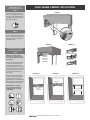 2
2
-
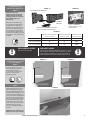 3
3
-
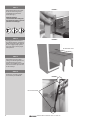 4
4
-
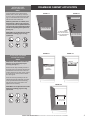 5
5
-
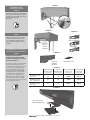 6
6
-
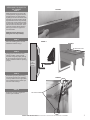 7
7
-
 8
8
-
 9
9
-
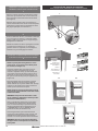 10
10
-
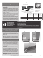 11
11
-
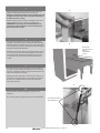 12
12
-
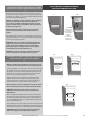 13
13
-
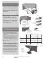 14
14
-
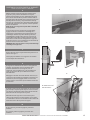 15
15
-
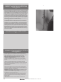 16
16


Rev-A-Shelf 4WCTM-RM-1835DM-1 Operating instructions
- Type
- Operating instructions
- This manual is also suitable for
Ask a question and I''ll find the answer in the document
Finding information in a document is now easier with AI
Related papers
-
Rev-A-Shelf 4WCTM-24DM2-162 Operating instructions
-
Rev-A-Shelf 4WCTM-RM-2150DM-2 Installation guide
-
-
Rev-A-Shelf 4WCTM-12CKWHSCDM1 Installation guide
-
 Walker Edison Furniture Company 4WDB-12 Operating instructions
-
-
-
-
-
Rev-A-Shelf 448-BCBBSC-8C Operating instructions

Other documents
-
Bosch SGU55M27SK/35 User manual
-
TrafficMASTER 18576 Installation guide
-
Everbilt 15734 Operating instructions
-
-
Projecta Solo 8000 Specification
-
Projecta Solo 9000 Specification
-
RTS Icw-6 User manual
-
Amazonia SC NELSON2 Installation guide
-
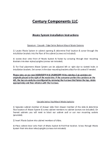 Century Components CC.CASBM17PF Installation guide
-
Panasonic CQ-C1100U Owner's manual
