Page is loading ...

INSTALLATION INSTRUCTIONS: 5707 BLIND CORNER ORGANIZER WITH SOFT CLOSE
12400 Earl Jones Way
Louisville, KY 40299
rev-a-shelf.com
Customer Service: 800-626-1126
5707 BLIND CORNER ORGANIZER WITH SOFT CLOSE
TOOLS REQUIRED:
45 MIN
ESTIMATED ASSEMBLY TIME:
CARE AND MAINTENANCE:
Clean with a damp cloth and
wipe parts dry.
I-5707-0717
1
16
VIDEO INSTRUCTIONS: WWW.REV-A-SHELF.COM/VIDEOS
FITTING PARTS LIST:
Description QTY
1
M6x12MM Button Head Screws
2
2
5/32x18MM Wood Screws
22
3
Adjustable Side Bracket
1
4
M5x8 Hex Flange Cross Bolts
3
5
Up Brackets
2
6
M5x6.5MM Bolts
2
7
Down Brackets
2
8
Gas Spring
1
9
Top Bracket
1
10
Connector
1
11
Door Stopper
1
12
Bottom Bracket
1
13
M4x6 Flat-Head Screws
4
14
Bottom Holder
1
15
Plastic Cover
1
16
Support Arm
1
17
M5x8MM Machine Screws
2
PANEL PARTS LIST:
Description QTY
A
Door Frame Baskets
2
B
Inside Frame Baskets
2
C
Door Frame
1
D
Swivel Frame
1
E
Inside Frame
1
1 2 3
4
5 7
8
9
13
12
14
15
10
16
17
11
B
D
E
C
A
6

Customer Service: 800-626-1126 | rev-a-shelf.com
2
)mm215( ”23/5-02
)mm5.784( ”61/3-91
1-5/16”
(33.5mm)
7-9/16”
(192mm)
7-9/16”
(192mm)
18-27/32
”
(478.5mm)
18-27/32
”
(478.5mm)
5/8”
(16mm)
5/8”
(16mm)
5/8
”
(16mm
)
5/8
”
(16mm)
5-53/64
”
(148mm
)
18-13/64
”
(462.5mm)
32-19/32
”
(828mm)
Find and mark all pre-drill locations
on cabinet by referring to Figure
1A for measurements. Once all
locations have been marked,
pre-drill using the 1/16” drill bit.
NOTE: If installing into a face
frame or frameless cabinet,
measurements must begin from
the outside edge of the cabinet.
If installing into an inset cabinet,
measurements must begin from
the inside edge of the face frame.
Attach the Inside Frame to the
cabinet oor and cabinet side
walls using (8) 5/32 x 18MM Wood
Screws (See Fig.1B).
Locate the (4) bolts on top of the
Inside Frame and tighten to lock
into place.
Attach Adjustable Side Bracket to
the cabinet wall using (3) 5/32 x
18MM Wood Screws (See Fig. 1B).
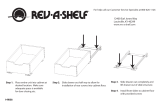
STEP 1
BOTTOM AND SIDE DIMENSION
Figure 1A
39” - 48
” (990-1219m
m
)
Figure 1B
NOTE: Measurements below are drawn in a frameless cabinet with an overlay door.
NOTE: Use a level to ensure balance.
1
16

INSTALLATION INSTRUCTIONS: 5707 BLIND CORNER ORGANIZER WITH SOFT CLOSE 3
Figure 2
Figure 3A
Figure 3B
Note: Do NOT attach the Bottom Holder directly to the
Swivel Frame. Screws are not provided for this as it
is not necessary. Simply use the (2) hole indentions as
reference points.
Loosely attach the Swivel Frame to
the Adjustable Side Bracket using
(3) M5x8 Hex Flange Cross Bolts.
NOTE: For face frame and
frameless applications with
overlay doors, the Swivel Frame
must be ush with the front
of the cabinet frame. For inset
applications, the Swivel Frame
must be installed back from the
front of the cabinet frame the
thickness of the door panel.
Once aligned according to
application type, rst secure the
(3) M5x8 Hex Flange Cross Bolts
from earlier and then use (2) 5/32 x
18MM Wood Screws to secure the
frame to the cabinet oor
(See Fig. 2).
STEP 2
Attach the Support Arm to the
bottom of the Swivel Frame using
(2) M6 x 12MM Button Head
Screws. Pull the Swivel Frame open
to allow better access for next step
(See gure 3A).
Locate the (2) hole indentions on
the bottom of the Swivel Frame.
Align the short edge of the Bottom
Holder to these indentions then
attach the long portion of the
Bottom Holder to the cabinet
oor with (2) 5/32 x 18MM Wood
Screws (See Fig. 3B).
STEP 3

Customer Service: 800-626-1126 | rev-a-shelf.com
4
10-15/16” (260mm) - 5707-15
13-25/64” (340mm) - 5707-18
)mm096-094( ”46/11-72 - ”46/91-91
”61/51
)mm42
(
Figure 4A
Figure 4B
Figure 5
Remove Screws
Find and mark all door panel
mount hole locations by referring
to Figure 4A for measurements.
Once all locations have been
marked, pre-drill using the 1/16”
drill bit.
NOTE: All door mount locations
must be in the thick portion of
the door.
Fit the Up Bracket into the top of
the Door Frame and the Down
Bracket into the bottom of the
Door Frame.
Attach the Door Frame to the back
of the door using (4) 5/32 x 18MM
Wood Screws (See Fig. 4B).
Tighten all (8) pre-installed
fasteners using Phillips Head Screw
Driver.
STEP 4
1
16
Remove all (4) screws from the
arms of the Door Frame and slide
the arms into the Swivel Frame
(See Fig. 5). Secure using the (4)
screws.
NOTE: These are the door tilt
adjustment screws.
STEP 5

INSTALLATION INSTRUCTIONS: 5707 BLIND CORNER ORGANIZER WITH SOFT CLOSE 5
Figure 6B
Figure 6A
Figure 6C
See Figure 6 to attach the Support
Arm to the Inside Frame using the
Connector.
First, remove the plastic cover and
occupying screw from the end of
the Bottom Holder. Then, attach
the Connector to the Bottom
Holder by re-attaching the plastic
cover and screw (See Fig. 6A).
Second, remove the M5x6.5MM
Bolt from the bottom of the Inside
Frame. Then, attach the Connector
to the Inside Frame by re-attaching
the M5x6.5MM Bolt (See Fig. 6B).
NOTE: For blind left application,
attach to the hole furthest on the
right. For blind right application,
attach to the hole furthest on
the left.
Third, remove the M5x6.5MM
Bolt from the Support Arm. Then,
attach the Connector to the
Support Arm by re-attaching the
M5x6.5MM Bolt (See Fig. 6C).
STEP 6

Customer Service: 800-626-1126 | rev-a-shelf.com
6
Locate the (4) pre-tapped holes on
the Swivel Frame. With the knobs
facing outward, attach the Top
Bracket and the Bottom Bracket
to the Swivel Frame using (4)
M4x6 Flat Head Screws. NOTE:
Top Bracket is attached to the
uppermost holes on the Swivel
Frame.
With the thinner portion of the
Gas Spring pointing down, snap
the Gas Spring into position using
the knobs on the Top and Bottom
Brackets (See Fig. 7).
NOTE: Ensure the thinner
portion of the Gas Spring is
pointing down.
STEP 7
Left Side
Figure 7
Right Side

INSTALLATION INSTRUCTIONS: 5707 BLIND CORNER ORGANIZER WITH SOFT CLOSE 7
Figure 8BFigure 8
Refer to Figure 8A on how to
properly dis-assemble and
re-assemble the Door Stopper.
Attach the Door Stopper to the
Connector (See Fig. 8B).
NOTE: Door Stoppers are meant
to prevent the cabinet door from
opening too far and potentially
damaging adjacent cabinets. The
position of the Door Stopper will
vary by user preference.
STEP 8
Figure 8BFigure 8
Figure 9
Refer to Figure 9 on how to hang
the Baskets.
Locate the (2) Baskets with the
angled corners and hang them on
the hooks of the Door Frame. The
remaining (2) Baskets attach to the
hooks of the Inside Frame.
STEP 9

Customer Service: 800-626-1126 | rev-a-shelf.com
8
B
A
12400 Earl Jones Way
Louisville, KY 40299
rev-a-shelf.com
Customer Service: 800-626-1126
ORGANIZADOR DE ESQUINA CIEGA CON CIERRE SUAVE 5707
SYSTÈME DE RANGEMENT POUR COIN MORT AVEC FERMETURE EN DOUCEUR 5707
45 MIN
Clean with a damp cloth and
wipe parts dry.
1
16
WWW.REV-A-SHELF.COM/VIDEOS
FITTING PARTS LIST:
Description QTY
1
Tornillos de Cabeza de Botón de M6x12MM
Vis à Tête Ronde M6x12MM
2
2
Tornillos de Madera de 5/32x18MM
Vis à Bois 5/32x18MM
22
3
Soporte Lateral Ajustable / Support Latéral
Réglable
1
4
Tornillos Hexagonales M5x8
Boulons hexagonaux à bride en croix M5X8
3
5
Soportes Superiores / Supports Supérieurs
2
6
Tornillos de M5x6.5MM / Boulons M5x6.5MM
2
7
Soportes Inferiores / Supports Inférieurs
2
8
Resorte de Gas / Ressort à gaz
1
9
Soporte Superior / Support du Haut
1
10
Conector / Connecteur
1
11
Tapón de la Puerta / Arrêt de Porte
1
12
Soporte Inferior / Support du Bas
1
13
Tornillos de Cabeza Plana de M4x6
Vis à tête plate M4x6
4
14
Sostenedor Inferior / Support du Bas
1
15
Cubierta Plástica / Couvercle en Plastique
1
16
Brazo del Soporte / Bras de Support
1
17
Tornillos de Máquina de M5x8MM
Vis Machine M5x8MM
2
PANEL PARTS LIST:
Description QTY
A
Canastas del Marco de la Puerta
Paniers du cadre de la porte
2
B
Canastas del Marco Interior
Paniers du cadre intérieur
2
C
Marco de la Puerta
Cadre de la porte
1
D
Marco Giratorio
Cadre pivotant
1
E
Marco Interior
Cadre intérieur
1
1 2 3
4
5 7
8
9
13
12
14
15
10
16
17
11
D
E
C
6
INSTRUCCIONES DE INSTALACIÓN
INSTRUCTIONS D’INSTALLATION
Herramientas requeridas:
Outils Requis:
Tiempo estimado de ensamblado
Durée de l’installation:
Cuidado/ Entretien:

Customer Service: 800-626-1126 | rev-a-shelf.com
16
12400 Earl Jones Way
Louisville, KY 40299
rev-a-shelf.com
Customer Service: 800-626-1126
/