Page is loading ...

CREWSERIES
RACKCONVEYORDISHMACHINES
TECHNICALMANUAL
INSTALLATIONMANUALFOREXPORTUNITS
SERVICEMANUALFORDOMESTICUNITS
ELECTRICALLYHEATEDMODELS:
CREW44
July27,2010
P/N07610‐003‐78‐18(RevisionA)
JacksonMSC,LLC
P.O.Box1060,Hwy25E
Barbourville,KYUSA
1.606.523.9795
www.jacksonmsc.com


Revision
Letter
Revision
Date
MadeBy ApplicableECNs Details
A 07-27-10 CW/JC N/A Initial release of manual

TABLEOFCONTENTS
Specifications
OperatingParameters Page6
NotesRegardingElectricalRequirements Page7
ElectricalRequirements Page8
Instructions
InstallationInstructions Page10
CurtainInstallationInstructions Page15
OperatingInstructions Page16
DelimingInstructions Page18
Maintenance
Troubleshooting Page19
PartsSection
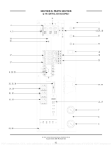
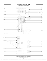
ControlBoxAssembly Page20
Overloads Page22
MiscellaneousElectricalComponents Page23
WashHeaterandHeaterShroudAssemblies Page24
WashHeaters Page25
DoorAssembly Page26
WashDoorSpringAssembly Page28
PlumbingAssembly,MainWaterInlet Page29
WashTankFillAssembly Page30
WashManifoldandArmAssembly Page31
RinseAssembly Page33
Crew44PawlBarAssembly Page35
PawlBarBracketAssembly Page36
PawlBarGutterAssembly Page37
RackPaddleAssembly Page38
RinsePaddleAssembly,L‐R Page39
DrainAssemblyParts Page40
Covers,GuardsandPanels Page41
Brackets Page42

TABLEOFCONTENTS(CONTINUED)
PartsSection
DriveAssembly Page45
BoosterHeaterOption Page47
MiscellaneousParts Page43
VentilationCowlParts Page44
ElectricalDiagramsandSchematics
BoosterHeaterSchematic(3Phase) Page48
BoosterHeaterSchematic(1Phase,12KW) Page49
BoosterHeaterSchematic(1Phase,18KW) Page50
TemperatureBoard Page51
Schematic,CREW44(208‐230‐460/60/3Phase) Page52
Schematic,CREW44(208‐230/60/1Phase) Page53

6
PageCreated:05‐04‐2010
Revised:N/A
CREWTechnicalManual(07610‐003‐78‐18)
OperatingParameters
ModelDesignation:CREW44
OperatingCapacity:
RacksperHour218
DishesperHour 3488
GlassesperHour 7848
TankCapacity(gallons):
WashTank35.6
ElectricalLoads(asapplicable):
WashMotorHP3.0
DriveMotorHP0.25
WashHeaterKW15or18
NOTE:Always refer to the machine data
plate
for specific electrical and water requirements.
The material provided on this page is for refer‐
ence only and is subject to change without no‐
tice.
HOTWATERSANITIZING
WaterTemperatures(Fahrenheit):
MinimumWashTemperature 160
MinimumRinseTemperature 180
IncomingWaterTemperature
12KWBooster 140
18KWBooster 110
CHEMICAL
SANITIZING
WaterTemperatures(Fahrenheit):
MinimumWashTemperature 120
MinimumRinseTemperature 120
IncomingWaterTemperature
12KWBooster80
18KWBooster 50
OtherWaterRequirements:
WaterFlowPressure(PSI) 15
FlowRateMinimum(GPM)1.18
WaterLineSize(NPT)1/2”
DrainLineSize(NPT)1‐1/2”

7
PageCreated:05‐04‐2010
Revised:N/A
CREWTechnicalManual(07610‐003‐78‐18)
NotesRegardingElectricalRequirements
Allelectricalratingsprovidedinthismanualareforreferenceonly.Alwaysrefertothemachinedataplate
togettheexactelectricalinformationforyourmachine.Allelectricalworkperformedonmachinesshould
bedoneinaccordancewithapplicablelocal,state,territorialandnationalcodes.Workshouldonlybeper‐
formedbyqualifiedelectriciansandauthorizedserviceagents.AlistofJacksonAuthorizedServiceAgencies
islocatedinthebackofthismanual.
NotethatallelectricalwiringusedintheCREWseriesofmachinesmustberated,ataminimum,for100C
(212F).Furthermore,usecopperconductorsonly.
Whereapplicable,heatingelementamperagedrawshavebeenadjustedfortheassumedinputvoltage.Jack‐
sonassumesincomingvoltageswillbeeither208,230or460volts.Someoftheheatingelementsusedin
ourmachinesareactuallyratedforothervoltages,suchas240 or480 volts.Always verify the amperage
drawofthemachineinoperationwhensizingcircuitprotection.
Ifyourmachineisequippedwiththeoptionalrinseheater,notetherinseheaterhasitsownelectricalcon‐
nectionandthereforerequiresaseparateservice.Amperageloadsformotorsandheatersarecalledouton
themachinedataplatefortheinstallation/servicetechnician.
TheelectricalconfigurationsoftheCREWseriesofmachinesareasfollows:
AvailableElectricalCharacteristics:
208volt,60Hz,singlephase
230volt,60Hz,singlephase
208volt,60Hz,threephase
230volt,60Hz,threephase
460volt,60Hz,threephase
AvailableWashTankHeaters:
15KW(standard)
18KW(optional)
AvailableRinseHeaters(“BoosterHeaters”):
None(standard)
12KW(40Friseintemperature)
18KW(70Friseintemperature)

8
PageCreated:05‐04‐2010
Revised:N/A
CREWTechnicalManual(07610‐003‐78‐18)
ElectricalRequirementsforCREW44
Volts Ph Freq
Wash
Motor
Amps
Drive
Motor
Amps
Wash
Heater
Amps
FLA MCA MOP
208 1 60 10.0A 1.8A 72.1A 83.9A 86.4A 96.4A
230 1 60 10.0A 1.8A 59.9A 71.7A 74.2A 84.2A
208 3 60 8.6A 1.1A 41.6A 51.3A 53.5A 62.1A
230 3 60 8.4A 1.1A 34.6A 44.1A 46.2A 54.6A
460 3 60 4.2A 0.6A 17.3A 22.1A 23.2A 27.4A
CREW44,15KWWashHeater
Volts Ph Freq
Wash
Motor
Amps
Drive
Motor
Amps
Wash
Heater
Amps
FLA MCA MOP
208 1 60 10.0A 1.8A 86.5A 98.3A 100.8A 110.8A
230 1 60 10.0A 1.8A 78.3A 90.1A 92.6A 102.6A
208 3 60 8.6A 1.1A 50.0A 59.7A 61.9A 70.5A
230 3 60 8.4A 1.1A 45.2A 54.7A 56.8A 65.2A
460 3 60 4.2A 0.6A 22.6A 23.2A 23.7A 27.9A
CREW44,18KWWashHeater
Volts Ph Freq
Wash
Motor
Amps
Drive
Motor
Amps
FLA MCA MOP
208 1 60 10.0 1.8A 11.8A 14.3A 24.3A
230 1 60 10.0 1.8A 11.8A 14.3A 24.3A
208 3 60 8.6 1.1 9.7A 11.9A 20.5A
230 3 60 8.4 1.1 9.5A 11.6A 20.0A
460 3 60 4.2 0.6 4.8A 5.9A 10.1A
CREW44S
Note:0nthe208voltmachines,therinseheaterisactuallyratedat17.2KW

9
PageCreated:05‐04‐2010
Revised:N/A
CREWTechnicalManual(07610‐003‐78‐18)
ElectricalRequirementsforBoosterTanks
Volts Ph Freq
Rinse
Heater
Amps
FLA
208 1 60 57.7A 57.7A
230 1 60 47.9A 47.9A
208 3 60 33.3A 33.3A
230 3 60 27.7A 27.7A
460 3 60 13.8A 13.8A
40°FRise‐12KWBooster
Volts Ph Freq
Rinse
Heater
Amps
FLA
208 1 60 82.7A 82.7A
230 1 60 71.9A 71.9A
208 3 60 47.7A 47.7A
230 3 60 41.5A 41.5A
460 3 60 20.7A 20.7A
Note:0nthe208voltmachines,therinseheaterisactuallyratedat17.2KW
70°FRise‐18KWBooster

10
PageCreated:05‐04‐2010
Revised:N/A
CREWTechnicalManual(07610‐003‐78‐18)
INSTALLATIONINSTRUCTIONS
VISUAL INSPECTION:Beforeinstallingtheunit,checkthecontainerandthemachinefordamage.A
damagedcontainermaybeanindicationthereispossibledamagetotheproduct.Ifthereisanytypeofdam‐
agetoboththecontainerandtheunit,DONOTTHROWAWAYTHECONTAINER. The dish‐machine has
beenpreviouslyinspectedatthefactoryandisexpectedtoarrive to you in new, undamaged condition.
However,roughhandlingbycarriersorothersmayresultindamagetotheunitwhileitisintransit.Ifsuch
asituationoccurs,DONOTRETURNTHEUNITTOJACKSON.Instead,contactthecarrierandaskthemto
sendarepresentativetothesitetoinspectthedamage.Youshouldrequestthataninspectionreportbe
completed.Youmustcontactthecarrierwithin48hoursofreceivingthemachineinordertoreportpossi‐
blefreightdamage.Youarealsoencouragedtocontactthedealerthroughwhichyoupurchasedtheunit.
UNPACKING THEMACHINE:Themachineshouldbeunboxedandremovedfromthepalletprior to
installing. Also remove the wooden lift beams and their associatedbracketsaftertheunithasbeenposi‐
tioned.Openthefrontdoorandremoveallofthematerialsfromtheinside.Onceunpacked,verifythereare
nomissingpartstothebestofyourability.Ifyoudiscoverapartismissing,contactJacksonimmediately.
LEVELTHEDISHMACHINE:Thedish‐machineisdesignedtooperatewhilelevel.Thisisimportantto
preventanydamagetothemachineduringoperationandtoensurethebestresultspossible.Theunitcomes
equippedwithadjustablebulletfeet,whichcanbeturnedusingapairofpliers.Verifytheunitislevelfrom
fronttobackandsidetosidepriortomakinganyelectricalorplumbingconnections.
PLUMBINGTHEMACHINE:Allplumbingconnectionsmustbemadetoadheretolocal,state,territorial
andnationalcodes.Theinstallingplumberisresponsibleforensuringtheincomingwaterlinesareflushed
ofdebrispriortoconnectingtothemachine.Notethatchipsandmaterialsfromcuttingprocessescanbe‐
comelodgedinthesolenoidvalvesandpreventthemfromopeningorclosing.Anyvalvesthatarefoundto
befouledordefectivebecauseofforeignmatterleftinthewaterline,andanysubsequentwaterdamage,are
nottheresponsibilityofthemanufacturer.
Waterhardnessshouldbeamaximumof6grainspergallon.Hardwatershouldbetreatedpriortobe
usedbythemachine.Ironinthewaterlinecancausestaining.Afilterdesignedtoremoveironfromthewa‐
tersupplyishighlyrecommendedforsuppliesinexcessof0.1ppm.
Yourdish‐machinecomeswithaWaterPressureRegulatingValve.TheCREWincorporatesaflowpres‐
sureof15PSIfortheincomingwaterline.Donotconfusestaticpressurewithflowpressure.Staticpressure
isthepressurewhenthereisnoflowandthevalvesareclosed;flowpressureiswhenthewaterisrunning
intothemachine.TheWPRVshouldbeadjustedtotheproperflowpressureataminimum.
Thewatersupplylineshallbe1/2”NPTminimumandmustbeabletoprovidewaterattheminimum
temperatureindicatedonthemachinedataplate.
Itisrecommendedashut‐offvalvebeinstalledtoallowisolatingthedish‐machinefromthewatersys‐
temintheeventmaintenanceorotheractivitiesrequireit.Also,itissuggestedthatashockabsorberbein‐
stalledontheincomingwaterline.Thispreventswaterhammer(hydraulicshock),inducedbythesolenoid
valveasitoperates,fromcausingdamagetotheequipment.

11
PageCreated:05‐04‐2010
Revised:N/A
CREWTechnicalManual(07610‐003‐78‐18)
INSTALLATIONINSTRUCTIONS(CONTINUED)
CONNECTINGTHEDRAINLINE:ThedrainfortheCREWisagravitydischargedrain.Allpipingtothe
machinedrainmustbeaminimum1‐1/2”NPTANDSHALLNOTBEREDUCED.Theremustalsobeanair
gapbetweenthemachinedrainlineandthefloorsinkordrain.Ifagreasetrapisrequiredbycode,itshould
haveaflowcapacityof30gallons.
STEAMLINECONNECTIONS:Somemachinescoveredinthismanualaredesignedtouselowpressure
steamasasourceofheatforthewashtank.Thosemachinescomewithlinesbywhichanoutsidesourceof
steam(i.e steam booster) isconnected.Connectall steam linesfromtheboostertothemachineinaccor‐
dance with the booster manufacturer’s instructions. Ensure thatallapplicablecodesandregulationsare
adheredto.Seethemachinedataplateforinformationrelatedtosteamflowrequirements.
ELECTRICALPOWERCONNECTIONS:Allelectricalconnectionsaretobemadeinaccordancewithap‐
plicableportionsoflocal,state,territorialandnationalcodes.
DISCONNECTELECTRICALPOWERSUPPLIESANDTAGOUTINACCORDANCEWITHAPPROPRIATE
PROCEDURESANDCODESATTHEDISCONNECTSWITCHTOINDICATEYOUAREWORKINGONTHATCIR‐
CUIT.
Thismanualprovidesreferenceinformationregardingelectricalrequirementsandloads,butthatinfor‐
mationmaychangewithoutnotice.Alwaysrefertothemachinedataplate for voltage requirements, ma‐
chinevoltage,totalamperageloadandserialnumber.Ifyoucannotreadyourdataplatebecauseithasbeen
damaged,youshouldcontactJackson.
Themainpowerterminalblocks(forthedish‐machineandfortherinseboosterheater,ifapplicable)
are located atthe top ofthe machine. Youwill have toremove the top cover toaccesstheseconnections.
Routeincomingpowerlineswithinconduitthatwillconnectviafittingstothepre‐punchedholesinthe
backoftheunit.Installpowerandgroundwirestolugsasindicatedbytheappropriatedecalsinthecontrol
box.Usecopperconductorsonly.Useofaanti‐oxidationagentis permissible on the power connections.
Tightenallconnections.
Verifytheincomingvoltagematchesthevoltageindicatedonthedecalnexttotheincomingpowerpre‐
punchedhole.
Pleasenotethedish‐machinehasaseparatepowerconnectionfromtherinseboosterheaterandthe
circuit protection requirements are different for each. Referto the machine data plate for information on
minimumcircuitprotection.
DISHMACHINEVENTILATION:Thedish‐machineshouldbelocatedwithprovisionsforventingintoan
adequateexhausthoodorventilationsystem.Thisisessentialtopermitefficientremovalofthecondensa‐
tionexhaust.Ensuretheexhaustsystemisacceptableinaccordancewithapplicablecodesandstandards.
Note: any damage that iscaused bysteam and/or moisturedue to improper ventilationis NOT
coveredunderthewarranty.

12
PageCreated:05‐04‐2010
Revised:N/A
CREWTechnicalManual(07610‐003‐78‐18)
INSTALLATIONINSTRUCTIONS(CONTINUED)
TheCREWhasthefollowingventilationrequirements:
LoadEnd:200CFM
UnloadEnd:200CFM
Theexhaustsystemmustbesizedtohandlethisvolumeforthedish‐machinetooperateinthemanner
itwasdesignedto.
THERMOSTATS:ThethermostatsonyourCREWunithavebeensetatthefactoryforthewashtank.
Theyshouldonlybeadjustedbyanauthorizedserviceagent.
CHEMICAL FEEDER EQUIPMENT:YourCREWdish‐machineDOESNOTCOMEWITHANINTEGRAL
CHEMICALSUPPLY/FEEDERSYSTEM.YoumustconnecttheCREWtoathirdpartychemicaldispenserthat
meetstherequirementsofNSFStandard29forthemachinetooperatecorrectly.
Youshouldcontactyourchemicalsupplieraboutconnectingadispensertoyourdish‐machine.Chemi‐
caldispensersmustbesetforthetypeandconcentrationofchemicalsbeingusedandthereareseveralfac‐
torsthathavetobetakenintoaccount.
Detergentusageandwaterhardnessaretwofactorsthatcontributegreatlytohowefficientlyyourdish‐
machinewilloperate.Usingtheproperamountofdetergentcanbecome,intime,asourceofsubstantialsav‐
ings.Aqualifiedwatertreatmentspecialistcanexplainindetailtoyouwhatisneededtogainthemaximum
efficiencyfromyourdetergent.
TheCREW dish‐machine is ableto operate ineither hot watersanitizingmodeorchemicalsanitizing
mode.Yourunitshouldbeclearlymarkedastothemodeitisin.Ifyoucannotdeterminethis,contactJack‐
sonimmediatelyforassistance.
Itisimportanttorememberthatifyoudecidetooperatetheunitinchemicalsanitizingmode,youmust
ensureanappropriatechlorine‐basedsanitizerisusedinthefinalrinseline.

13
PageCreated:05‐04‐2010
Revised:N/A
CREWTechnicalManual(07610‐003‐78‐18)
INSTALLATIONINSTRUCTIONS(CONTINUED)
DETERGENT INJECTION POINT.
ANOTHER BULKHEAD PLUG
IS PROVIDED ON THE LEFT SIDE
OF THE UNIT
1-1/2" NPTF DRAIN CONNECTION
ADJUSTABLE BULLET FEET
BULKHEAD OPENING FOR
CONDUCTIVITY PROBE
CHEMICAL TUBE
INSERTION POINT
875"
INLET WATER FITTING
1/2" NPTF
MAIN ELECTRICAL
CONNECTION OPENING
1.375"
BOOSTER HEATER
ELECTRICAL CONNECTION
OPENING
1.375"
SHOWN FROM REAR OF LEFT TO RIGHT UNIT.
RIGHT TO LEFT UNIT IS MIRRORED

14
PageCreated:05‐04‐2010
Revised:N/A
CREWTechnicalManual(07610‐003‐78‐18)
INSTALLATIONINSTRUCTIONS(CONTINUED)
REMOVE THIS JUMPER
WIRE TO ALLOW FOR
TABLE LIMIT SWITCH
CONNECTIONS
CONNECTION POINT
FOR VENT FAN SIGNAL
CONNECTION FOR
DETERGENT
DISPENSER
RINSE AID & SANITIZER
CONNECTION SIGNALS
FROM DOOR SWITCH
TO PLC
TABLE LIMIT
SWITCH
CONNECTION
ELECTRICALCONNECTIONPOINTSFORTABLELIMITSWITCH,
VENTILATIONFANSIGNAL&CHEMICALDISPENSINGSYSTEMS
SIGNALBOARDISLOCATEDINTHEMAINCONTROL
BOXBEHINDTHELOWERDRESSPANEL
CHEMICALDISSPENSERTUBECONNECTIONPOINTSTORINSEINJECTOR
P:PRESSURESWITCH(1/4”NPT)
S:SANITIZER(1/8”NPT)
R:RINSEAID(1/8”NPT)

15
PageCreated:05‐04‐2010
Revised:N/A
CREWTechnicalManual(07610‐003‐78‐18)
CURTAININSTALLATIONINSTRUCTIONS
DETERMINING CONVEYOR DIRECTION: Your CREW machine will be configured for
eitherLefttoRightorRighttoLeftoperation.DirectionisalwaysfromtheLoadEndto
theUnloadEnd,asshownintheexamples.
LefttoRightOperation
LoadEnd UnloadEnd
IMPORTANCEOFPROPERCURTAINPLACEMENT:ThecurtainsinsidetheCREWmachinearerequired
tobeinstalledinaparticularfashion.Notetheapproximatelocationsforeachtypeofcurtainintheabove
illustrations. S=Short, L=Long &XL=Extra Long. See the chartbelow for actual curtain lengths and part
numbers.
Legend Length PartNumber QTY
S 12” 08415‐131‐73‐44 1
L 19” 08415‐002‐14‐41 2
XL 24.25” 08415‐002‐47‐37 2
CurtainRod 20.50” 05700‐003‐77‐52 5
OntheCREW44models,thereare5locationsfortheplacementofcurtainsinsidethe
machine,startingfromtheloadendandgoingallthewaytotheunloadend.Thetableto
theleftindicateswhatsizecurtaingoesonwhichcurtainhook.Ifyouaremissinganyof
thecurtaincomponents,itis very importantyouobtainreplacementpartsinorderto
makesureyourunitrunscorrectly.Curtainsareusedtocontroltheaircurrentsinside
yourunitandtheygreatlyassistinmaintainingtheheatnecessarytokeepenergycosts
down.
RighttoLeftOperation
UnloadEnd LoadEnd
XLSLLXL XLLLSXL

16
PageCreated:05‐04‐2010
Revised:N/A
CREWTechnicalManual(07610‐003‐78‐18)
OPERATIONINSTRUCTIONS
PREPARATION:Beforeproceedingwiththestart‐upoftheunit,verifythefollowing:
Thedrainstopperisinstalled;
Thestrainersareinstalled;
Thepawlbarisinstalledandsecure;
Theactuatorswitchesmovewithrelativefreedomanddonotbind;
Thecurtainsareinstalledcorrectly
POWERUP:Toplacetheunitinstandby,presstheStartButtononthefrontofthemachine.
Theunitwillautomaticallydetermineifthereis aproperwater levelinthewashtank.Ifnot,the
unitwillbegintofilluntiltheappropriatelevelisreached.
Ifthewashtanktemperatureisnotattheminimumlevelforthe mode of operation, the wash
heater will energize. Refer to the machine data plate for a better understanding of the minimum
temperaturesneededtooperatetheunitcorrectly.Itmaytakeseveralminutesforthewashtankto
heatup,dependingontheinitialtemperatureofthewater.
Ifyourmachineisequippedwitharinseboosteroption,notetheboostershall turn on whenthe
unitturnson.
Ifyourmachineisheatedwithasteambooster,thenyouwillneedtoturnonthesteamboosterin
accordancewiththemanufacturer’sinstructions.
Itisimportantthatyoudonotattempttostarttheunituntil:
Theunitstopsfilling;
Theunithasreachedtheappropriatewashtanktemperature.
FIRSTRACK:Thefirstrackofwarethatyouplaceintotheunitusuallyhastheeffect ofveryquickly
reducingthetemperatureofthewashtank.Thisisbecauseyouareintroducingcoldmaterialsintothedish‐
machineenvironmentandtheunithastocirculatewatertogettheheatingcyclegoing.Youmayhavetorun
thefirstrackthroughtheunitagain.Anytimetheunithasnotbeenoperatedforanextendedperiodoftime
thisispossible,butunlikely.Thisisusuallydependentonthetypeofwareyouareusing,itstemperature
andtheambienttemperatureofthekitchenarea.Alwaysobservethetemperaturesofthewashandrinse
whenfirststartingtheunittoensureproperoperation.
WAREPREPARATION:Properpreparationofwareisessentialforthesmooth,efficient operation of
yourdish‐machine.Ifdoneproperly,youcanexpecttohavefew
erre‐washesandusesubstantiallylessde‐
tergent.Anywareplacedinsidethemachineshouldhaveallsolidfoodwasteandscrapsremoved.Itisrec‐
ommendedthatwarealsobesprayeddownpriortoentryintothedish‐machine.
Placecupsandglassesupsidedowninrackssotheydonotholdwaterduringthecycle.Presoakflat‐
wareinwarmwatertoassistingettingstuck‐onmaterialoff.Loadplatesandsaucersinthesamedirection
(withthesurfacefoodisplacedonfacingtowardstheunloadendofthemachine).
WASHINGARACKOFWARE:TheCREWmachineisdesignedtowashwareplacedinarack.Underno
circumstanceshouldanymaterialsbeplacedinsidetheCREWmachinethathavenotbeenproperlysecured

17
PageCreated:05‐04‐2010
Revised:N/A
CREWTechnicalManual(07610‐003‐78‐18)
OPERATIONINSTRUCTIONS(CONTINUED)
intoadishrack.
Tostartthecycle,gentlypushtherackintotheunitontheloadend.Oncethewashactuatorhasmoved
sufficiently,theunitwillautomaticallybegintoconveythedishrackthroughtheunit.Theentirecycleis
automatic.
OPERATIONAL INSPECTIONS: It is recommended that operators periodically review the following
itemswhilethemachineisoperating.Alloftheseitemsareimportanttooperatingthemachineinaneffi‐
cientmanner.
Review wash and rinse temperatures and compare to the minimums required by the data plate.
Lowtemperaturescanbeanindicationofafaultythermostat,athermostatthatneedsadjustment
orsomeotherconditionthatneedstobeaddressed.
Verifythepanstrainersarenotbecomingclogged.Keepingthesefreeofsoilanddebrisallowsfor
muchbetterflowofwaterthroughthemachineandpreventsanysortofredepositissues.
Waterpressure.TheCREWisdesignedtorunataminimumof15PSI;anylowerthanthatandyou
won’thaveenoughrinsewatertoproperlyremovedetergentfromyourware.
Washandrinsearmnozzlesshouldbefreeofdebris.Opennozzlesareessentialtotheoperationof
thedish‐machine.
SHUTDOWN:Toshuttheunitdown,presstheStartSwitchonthefrontofthemachine.Todrainthe
machine,openthefrontdoorandpulluponthedrainreleaseinsidetheunit.Ifyouhaveasteamboosterfor
heatingthedish‐machine,shutitdowninaccordancewithitsmanufacturer’sinstructions.
CLEANING:Itisrecommendedtheunitbecleanedatleastonceevery24hoursorattheendoftheday.
Cleaningassistsinmaintainedtheefficientoperationoftheunitbyremovingsoilanddebristhatmightoth‐
erwisebecometrappedinnozzlesorgetdepositedontoware.
Curtains:shouldbe removedandscrubbedwith milddetergent/soapandabrushandallowed to
airdry.
Strainers:shouldberemovedandhavedebrisscoopedout.Neverhitstrainerstoremovedebris;
thiscancausethemtowarpandnotseatcorrectly.Rinseunderwatershouldremovetherestofany
debristrappedinthepart.
WashArms:thewasharmscanberemovedusinga7/16”driver;however,theCREWisdesignedso
thewasharmsareliterallyself‐cleaning.Operatorshavetheabilitytoflushthearmsbyremoving
theplasticendcapsand running a rackthroughthe unit. This shouldonlybedoneasacleaning
functionwithanemptyrackandatubthatisfilledwithwater.
InternalChamber:Milddetergent/soapandadishragshouldbeallthatisneededtocleantheinside
ofthemachine.Strainersandthepawlbarshouldberemovedto
provideasmuchroomaspossible.
External Areas: The outside of the unit should be cleaned with a standard countertop or general
cleaner.Neverattempttocleaninsideanycompartments,boxesorchambersthataresecuredwith
acover.Thesenormallycontainliveelectricalcomponents.
DONOTCLEANTHEUNITWITHANYTYPEOFMETALLICSCRUBBINGSPONGE!

18
PageCreated:05‐04‐2010
Revised:N/A
CREWTechnicalManual(07610‐003‐78‐18)
DELIMINGINSTRUCTIONS
Toproceedwiththedelimingoperation,fillthedish‐machineandthecorrectamountofdelimingsolu‐
tionasrecommendedbythemanufacturerofthechemicals.Thetankcapacitiesofthemachinecanbefound
onthespecificationspageofthismanual.
Afterthechemicalsareadded,performthefollowingsteps:
1. FliptheNORMAL/DELIMESwitchtoDELIME.
2. Disconnectorturnoffchemicalfeederpumps.
3. Closealldoors.
4. PresstheStartSwitchandrunthemachineforthelengthoftimerequiredbythechemicalsolution
manufacturer.
5. PresstheStartSwitchtoshuttheunitoff.
6. Openthedoorandstepawayfor5minutes.
7. Inspecttheinsideoftheunittodetermineifyourexpectationshavebeenmet.Ifnot,youmayneed
torunthedelimingsolutionthroughtheunitformoretime.
8. Onceclean,drainthemachinecompletely.
9. Closethedoor.
10. Refilltheunit.
11. PresstheStartSwitchandruntheunitinManualfor10minutes.
12. PresstheStartSwitchtoturnofftheunit.
13. Openthefrontdoor.
14. Draintheunit.
15. FliptheNORMAL/DELIMESwitchtoNORMAL.
16. Yourmachineisreadytouse.
Thisequipmentisnotrecommendedforusewithdeionizedwaterorotheraggressivefluids.Useof
deionizedwaterorotheraggressivefluidswillresultin
corrosionandfailureofmaterialsandcom‐
ponents.Useofdeionizedwaterorotheraggressivefluidswillvoidthemanufacturer’swarranty.

19
PageCreated:05‐04‐2010
Revised:N/A
CREW Technical Manual (07610-003-78-18)
TROUBLESHOOTING
Green LED lights are illuminated on the PLC when in opera-
tion. The POWER, OK & RUN lights indicate that 24VDC
power is available to the PLC and that is functioning properly.
If the RUN light is out, the operational program of the PLC
may have been corrupted or lost. Temporary power surges may
have occurred. Secure all power to the machine , wait for 30
seconds and restore power. Verify that the Green light is illumi-
nated to the 24vdc power supply immediately to the left of the
PLC. If the RUN light is still off, replace the PLC.
Refer to the illustration below for the designation of each LED.
Inputs correspond to the connections behind the top flip up
panel of the PLC and are marked I1 thru I8. Outputs correspond
to the connections behind the bottom flip up panel of the PLC
and are marked Q1 thru Q8.
Note: All outputs are fused. Q1 & Q2 outputs utilize 1.0 Amp
fuses and Q3-Q8 utilize .75 Amp fuses.
UTILIZE THESE SCREWS
FOR PLC REPLACEMENT
UTILIZE THESE SCREWS
FOR PLC REPLACEMENT
STATUS
INDICATING
LIGHTS
INPUTS
OUTPUTS
Alloperationalrelays
utilizegreenLEDindicat‐
inglightstoverifyproper
operation.Theserelays
aremountedimmediately
totherightofthePLC.
Pleaserefertotheillustra‐
tiontotherightforthe
relaysdesignation&tothe
appropriateschematicsfor
troubleshooting.

20
PageCreated:05‐04‐2010
Revised:N/A
CREW Technical Manual (07610-003-78-18)
PARTS SECTION: CONTROL BOX ASSEMBLY
1
10
9
21
21
6
8
7
11
4
15
2
3
14
5
18
18
13
19
19
22
19
25
20
20
23
20
17
17
24
12
16
7
7
8
8
8
8
DETAILOFFUSELOCATIONSFORPARTNUMBER05920‐002‐42‐13
/


