AJ-44C Series Technical Manual 7610-001-76-22
Issued: 03-21-2006 Revised: N/A
SECTION 5: PARTS SECTION
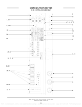
AJ-44 CONTROL BOX ASSEMBLY (CONTINUED)
63
ITEM QTY DESCRIPTION Mfg. No.
1 1 Electrical Box Weldment 05700-041-88-43
2 1 Terminal Block, 3 Pole 05940-011-48-27
3 1 Thermometer, 96” Lead 06685-111-68-49
4 6 Star Washer, External Tooth, 10-24 05311-273-02-00
5 6 Screw, 10-32 x 3/4” Long Phillips Trusshead 05305-011-62-17
6 1 Decal, Gauge 09905-021-72-29
7 1 Thermometer, 48” Lead 06685-111-68-48
8 1 Wire Lug, 2 AWG to 14 AWG 05940-200-76-00
9 1 Decal, Ground 09905-011-86-86
10 1 Screw, 10-32 x 1/2” Long Phillips Trusshead 05305-011-39-36
11 1 Decal, L1-L2-L3 09905-101-12-66
12 1 Light, Amber 05945-111-44-44
13 1 Light, Red 05945-111-44-45
14 1 Din Rail 05700-021-72-75
15 1 Circuit Breaker (200-380 Volt, 60 Hz Models Only) 5925-011-68-34
15 1 Circuit Breaker (CGP Models Only) 5925-111-64-18
16 1 Switch, ON/FILL - OFF/DRAIN 05930-301-46-00
17 2 Motor Contactor 05945-111-68-38
18 1 Heater Contactor 05700-011-71-44
19 1 Overload See Chart
20 1 Overload See Chart
21 3 Control Relay 05945-111-35-19
22 12 Screw, 6-32 x 3/8” Long Round Phillipshead 05305-171-02-00
23 1 Fuse (380 Volt-460 Volt, (all 60 Hz) Models Only) 5920-011-72-88
1 Fuse, 600 Volt Models Only 5920-002-75-95
24 1 Fuse Holder for (23) Above 5920-011-72-89
25 1 Transformer
200 Volt Model 05950-002-41-47
208-220-230-460 Volt Models 05950-011-68-35
208-220-230-460 Volt CGP Models 05950-002-46-10
380-415 Volt Models 05950-011-75-59
600 Volt Model 05950-002-23-77
26 4 Locknut, 10-24 with Nylon Insert 05310-373-01-00
27 1 Terminal Board 05940-002-78-97
28 1 Terminal Board 05940-021-89-41
29 3 Screw, 10-32 x 3/8” Long Phillips Trusshead 05305-173-12-00
30 2 Control Relay (CGP Models Only (Not Shown) 05945-111-72-51
MISCELLANEOUS PARTS NOT SHOWN:
Grommet, 1/2” OD x 3/8” ID 05325-011-46-73
Bushing, Heyco SB100 05975-210-09-00
Plug, Heyco 2700 G-875 05975-011-47-81
Control Box Cover 05700-031-66-88
Control Box Cover Hinge Weldment 05700-021-68-57
Control Hinge Rod 05700-011-68-58
Washer, Flat, S/S, 1/4” ID 05311-174-01-00
Cotter Pin 05315-011-68-56
MANUAL/DELIME Switch (located on rear of control box) 05930-301-22-18
MANUAL/DELIME Switch Decal (located on rear of control box) 09905-011-74-61
Copper Conductors Only Decal 09905-011-47-35
Control Box Leg 05700-011-71-47
Bolt, 1/4”-20 x 2-1/2” Long Hex Head 05306-011-83-52
Locknut, 1/4”-20 with Nylon Insert 05310-374-01-00
Component Mounting Plate (located inside the control box) 05700-031-67-03
Conduit Bracket 05700-021-70-88
PDF compression, OCR, web optimization using a watermarked evaluation copy of CVISION PDFCompressor


