Lutron Electronics EcoSystem T8 Digital Ballast Technical Manual

Type
Technical Manual
EcoSystem
technical guide
EcoSystem
Lutron’s first principle
is to take care of our customer.
Commitment to innovation
Lutron has been dedicated to producing innovative light control
solutions for commercial buildings of every type and style since 1961.
A dedication matched only by our commitment to quality,
performance, value and service for our customers.
World-class quality
Lutron quality is fueled by a relentless pursuit of the highest
standards. Constant improvement activities include an integrated
quality system, strict engineering guidelines, and world-class
quality and manufacturing processes.
Comprehensive light control solutions
for daylight and electric light
Lutron is your comprehensive resource for light control solutions
for any commercial or institutional application.
Architectural dimming systems
Daylight harvesting
Low-voltage switching systems
Floor plan based control software
Light management systems
Integrated light automation systems
Factory service plans
Please contact us for information on Lutron’s residential
light control products.
Worldwide sales and service
The Lutron team is here
to support you whenever
you need us.
Technical Support:
24 Hours/7 Days
1.800.523.9466
Customer Service:
8am-8pm ET
1.888.LUTRON1
Internet Support:
www.lutron.com/ecosystem
Lutron
|
01
The EcoSystem solution is designed to fulfill the needs of light
control in the 21st century. Specifically, EcoSystem revolutionizes
energy savings, flexibility, and maintenance in a way that changes
the workplace.
Designed for open office spaces and K-12/university classrooms,
EcoSystem easily integrates environment sensors, such as daylight
and occupancy sensors, with personal controls, such as wallstations
and infrared remotes. With up to 50% of energy use in offices
(60% of energy use in schools) going to lighting, the combined
effect of multiple environment sensors and personal controls
operating together brings unparalleled energy savings to spaces
that previously had none.
Beyond the energy savings, EcoSystem creates a more flexible
workspace. Composed of digital ballasts that have individual
addresses and communicate via control wires, EcoSystem ballasts
can be programmed, instead of wired, to work individually or as
a group. This eliminates the need for an area to be rewired when
changes take place, creating flexibility in a space that adjusts
to the shifting needs of a company.
Finally, EcoSystem reduces lighting system maintenance.
All of the environment sensors and personal controls connect
directly to any ballast, removing interfaces, power packs, and
control devices that on other systems require more parts,
programming and maintenance.
Annual electricity
use in office buildings
1
44% Lighting
24% Office Equipment
8% Ventilation
14% Space Cooling
3% Space Heating
8% Other
1 Source: Energy Information Administration Office, Energy
Statistics from the U.S. Government, Commercial Buildings
Energy Consumption Survey.
02
|
Lutron
www.lutron.com/ecosystem Lutron World Headquarters: 1.610.282.3800
Lutron®
|
why EcoSystem
?
EcoSystem
Technical Guide
02 Why EcoSystem?
04 How to Design a System
Components
06 Ballasts/BMFs
08 Daylight Sensors
10 Occupancy Sensors
12 IR Receiver and Remote
14 Wallstations
15 Programmer
16 Bus Supply
System Information
18 Wiring Overview
20 Design Examples
24-29 Technical Information
Lutron
|
03
Technical Support: 1.800.523.9466 … 24 hours/7 days (US/CAN)
To Order: 1.888.LUTRON1 … 8 am – 8 pm/M-F ET (US/CAN)
Lutron®
|
table of contents
Here are the 4 steps to designing an EcoSystem:
Step Ballast Selection
A Determine number of fixtures that will be connected to EcoSystem.
Note: Do not consider control zones, since they will be programmed rather than wired.
B Classify the type of ballast in each fixture.
Note: Use a Ballast Module Fixture-mounted (BMF) in conjunction with a ballast for dimming
down to 1% or for lamp types where EcoSystem is not yet available. A BMF connected
to any Eco-10
or Hi-lume
®
ballast gives full EcoSystem functionality to that ballast.
Step Sensor/Receiver Selection
Determine what sensors should be connected to EcoSystem.
Note: EcoSystem ballasts are compatible only with EcoSystem daylight sensors.
1
2
EcoSystem T8 Digital Ballast
pg. 06
EcoSystem Ballast Module Fixture-mounted (BMF)
pg. 07
20VDC Occupancy Sensor
pg. 10
EcoSystem Daylight Sensor
with IR Receiver
pg. 08
EcoSystem IR Receiver
pg. 12
EcoSystem T5 Digital Ballast
pg. 06
04
|
Lutron
www.lutron.com/ecosystem Lutron World Headquarters: 1.610.282.3800
EcoSystem
|
how to design a system
Step Control Selection
Determine what controls should be connected to EcoSystem.
Step Support Components
A Include 1 EcoSystem programmer for EcoSystem programming
B Include 1 bus supply for each room or area, up to a maximum of 64 ballasts
3
4
EcoSystem
IR Receiver
and Remote for
Personal Control
pg. 12
EcoSystem 1-Button
Wallstation with
Raise/Lower
and IR Receiver
pg. 14
EcoSystem 4-Button
Wallstation with
Raise/Lower
and IR Receiver
pg. 14
EcoSystem Programmer
pg. 15
EcoSystem Bus Supply
pg. 16
Ballasts BMF Daylight
Sensors
Occupancy
Sensors
IR Receiver
and Remote
Bus Supply
1 2
3
4
2
1
Wallstations
3
Programmer
4
Lutron
|
05
Technical Support: 1.800.523.9466 … 24 hours/7 days (US/CAN)
To Order: 1.888.LUTRON1 … 8 am – 8 pm/M-F ET (US/CAN)
EcoSystem T8 Digital Ballast
EC 5 T832 J (120, 277) (1, 2)
T8 Linear & U-Bent 32W, 120 or 277V, 4' Lamp
EC 5 T832 G 277 (2, 3)
T8 Linear & U-Bent 32W, 277V, 4' Lamp
EcoSystem T5 Digital Ballast
EC 5 T514 J (120, 277) (1, 2) T5HE Linear 14W, 120 or 277V
EC 5 T521 J (120, 277) (1, 2) T5HE Linear 21W, 120 or 277V
EC 5 T528 J (120, 277) (1, 2) T5HE Linear 28W, 120 or 277V
EcoSystem T8 and T5 Digital Ballast
Smooth and continuous dimming from 100% to 10%
Provides power for and responds to one occupancy sensor, one daylight
sensor, and one personal control input (infrared receiver or wallstation)
Communicates status and sensor inputs over the EcoSystem bus
Lamp current crest factor: Less than 1.7
Light output variation: Constant
+
/- 2% light output for line voltage
variations of
+
/- 10%
Lamp life: Average lamp life meets or exceeds
lamp manufacturer ratings
Total Harmonic Distortion (THD): model numbers with “J” have less
than 10% THD; model numbers with
G” have less than 20% THD
Maximum inrush current: 3 Amps per ballast at 277V
Ambient temperature operating range: 50 – 140ºF (10 – 60ºC)
Terminal blocks on the ballast accept the following wire gauges:
- EcoSystem bus: #16 – #18 AWG (1.29 – 1.02mm) solid
- Power wiring: #16 – #18 AWG (1.29 – 1.02mm) solid
- Class 2 sensor wires: #22 AWG (0.635mm) solid
Class P thermally protected
Meets ANSI C82.11 high frequency ballast standard
Meets FCC Part 18 non-consumer requirements for EMI/RFI emissions
Meets ANSI C62.41 category A surge protection standards
up to and including 4kV
Mounts using two screws inside a fluorescent fixture
Step Ballast Selection
1
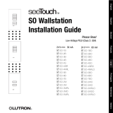
J Ballast Dimensions
L: 18.00" (457mm)
W: 1.18" (30mm)
H: 1.00" (25mm)
Mounting center: 17.70" (450mm)
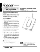
G Ballast Dimensions
L: 9.50" (241mm)
W: 2.38" (60mm)
H: 1.00" (25mm)
Mounting center: 8.9" (226mm)
06
|
Lutron
www.lutron.com/ecosystem Lutron World Headquarters: 1.610.282.3800
EcoSystem
|
ballasts
EcoSystem Ballast Module Fixture-mounted (BMF)
C5-BMF-2A
Allows integration of any Lutron Eco-10
or Hi-lume
®
phase-control ballast into the EcoSystem bus
Provides power for and responds to one occupancy sensor, one daylight
sensor, and one personal control input (infrared receiver or wallstation)
Universal voltage input: 120/240/277 V ~ 50/60 Hz
Dimming range: 100% to minimum ballast level
(10% for Eco-10, 1% for Hi-lume) relative light output
Ambient temperature operating range: 50 – 140ºF (10 – 60ºC)
Terminal blocks on the BMF accept the following wire gauges:
- EcoSystem bus: #16 – #18 AWG (1.29 – 1.02mm) solid
- Power wiring: #16 – #18 AWG (1.29 – 1.02mm) solid
- Class 2 sensor wires: #22 AWG (0.635mm) solid
Mounts using two screws either inside a fluorescent fixture
or in a rated electrical enclosure
If mounting outside a fluorescent fixture, can be up to 50' from ballast
Can be used with a Lutron dimming ballast to dim one control
zone of up to 2 Amps
BMF does not contain a 3-wire input
Capable of mechanical off through internal air-gap switch
Step Ballast Selection
120V or 277V
Ballast Module
(C5-BMF-2A)
Implementing an EcoSystem BMF
The BMF has input terminals that accept EcoSystem low-voltage sensors, controls and the bus
communication wires. It controls any Lutron Eco-10 or Hi-lume dimming ballast.
One-Line Diagram
1
Distribution Panel
EcoSystem
Bus Supply
(CS-1L-WM)
BMF (C5-BMF-2A)
Any Eco-10 or Hi-lume Ballast
BMF (C5-BMF-2A)
Dimensions
L: 9.30" (236mm)
W: 1.18" (30mm)
H: 1.00" (25mm)
Mounting center: 8.90" (226mm)
Any Eco-10 or Hi-lume Ballast
To other
Ballasts
or BMFs
Daylight
Sensors
Occupancy
Sensors
IR Receiver
and Remote
Bus Supply
2
3
4
2
Wallstations Programmer
3 4
Ballasts BMF
1
1
To other
Ballasts
or BMFs
120V or 277V
EcoSystem Bus
Communication Wires
3 #16 Power Wires
(Hot, Dimmed Hot, Neutral)
120V or 277V
Lutron
|
07
Technical Support: 1.800.523.9466 … 24 hours/7 days (US/CAN)
To Order: 1.888.LUTRON1 … 8 am – 8 pm/M-F ET (US/CAN)
EcoSystem
|
ballasts
EcoSystem Daylight Sensor with IR Receiver
C-SR-M1-WH
Automatically dim the lights when the available daylight
is high and brighten the lights when the available daylight
is low in order to maintain a specific light level in the space
Integrated IR receiver for EcoSystem programming
1 daylight sensor can control multiple fixtures or groups
of fixtures differently
Up to 8 daylight sensors can exist on a single EcoSystem bus
Total wire length to ballast (or BMF) must not
exceed 100' (30m)
Designed for Class 2 operation only
Operating voltage: Low-voltage Class 2, 20VDC
Analog signal: 0 – 20VDC
Daylight (photo) sensors from other manufacturers
are not compatible with EcoSystem
Step Sensor Selection
Daylighting
Design Statement: Use 1 daylight sensor for each zone of fenestration.*
If the zone extends more than 30' (9.14m), include a daylight sensor for
every 30' (9.14m) segment. Wiring a daylight sensor to one ballast allows
control of multiple ballasts on a bus.
2
Dimensions
H: 0.69" (17mm)
D: 1.18" (30mm)
Stem Length: 1.25" (32mm)
H
08
|
Lutron
www.lutron.com/ecosystem Lutron World Headquarters: 1.610.282.3800
* Fenestration: Any opening in a building’s envelope including windows, doors and skylights.
EcoSystem
|
daylight sensors
Step Sensor Selection
Wiring the Daylight Sensor
Wire color designations of the daylight sensor:
Red = 20VDC
Black = Common
White = IR Signal
Yellow = Daylight Sensor Signal
Make sure that the supply breaker
to the digital ballast is OFF when wiring
Connect the four conductors to the
four digital ballast terminals as shown
Note: The digital ballast accepts only
one IR input. Use of the IR input
for the daylight sensor precludes
the use of an infrared receiver
with the same digital ballast.
Pendant Fixture
Ceiling Tile or Fixture
2
Daylight Sensor
with IR Receiver
Arrow points toward the area
viewed by the sensor
Bottom of sensor
1-2 H
H
3' (0.9m)
H = Effective Window Height
Ballast Terminals
Pendant Fixture Ceiling Tile or Fixture
Red
Black
White
Yellow
White
Orange
Black
E1
E2
+20V
+20V
+20V
Common
Common
Common
IR
Occ
Daylight
Mounting the Daylight Sensor
Determine the proper location of the daylight
sensor using the adjacent diagrams.
The arrow on the daylight sensor points
toward the area viewed by the sensor
Place the daylight sensor so its viewing area
is centered upon the nearest window at a
distance of between 1-2 H from the window
The effective window height, H, starts
3' (0.91m) up from the floor or at the window
sill, whichever is higher, and ends at the top
of the window
Ensure that the view of the daylight sensor
is not obstructed
Do not position the daylight sensor in the well
of a skylight or above indirect lighting fixtures
Ballasts BMF
Daylight
Sensors
Occupancy
Sensors
IR Receiver
and Remote
Bus Supply
1 2
3
4
2
1
Wallstations
3
Programmer
4
Lutron
|
09
Technical Support: 1.800.523.9466 … 24 hours/7 days (US/CAN)
To Order: 1.888.LUTRON1 … 8 am – 8 pm/M-F ET (US/CAN)
22 AWG solid 105˚C only
EcoSystem
|
daylight sensors
Occupancy Sensor – Ceiling Mounted*
LOS-CUS-(500, 1000, 2000
)-WH Ultrasonic
LOS-CDT-(500, 1000, 2000
)-WH Dual technology
LOS-CDT-(500R, 1000R, 2000R
)-WH Dual technology
with second contact closure output
LOS-CIR-(450, 1500
)-WH Infrared
Denotes square feet of sensor coverage
Occupancy Sensor – Wall Mounted*
LOS-WDT-WH Dual technology
LOS-WDT-R-WH Dual technology
with second contact closure output
LOS-WIR-WH Infrared
No power pack is necessary, occupancy sensor receives
power from BMF
* Please visit www.lutron.com/ecosystem for a complete list of
occupancy sensors compatible with EcoSystem.
2
Dimensions
W: 6.12" (156mm)
H: 1.62" (41mm)
D: 2.31" (59mm)
Ceiling Mounted: 3/4" (19mm)
diameter hole for mounting
post (Lutron-supplied)
Dimensions
W: 3.75" (95mm)
H: 5.50" (140mm)
D: 4.00" (102mm)
10
|
Lutron
www.lutron.com/ecosystem Lutron World Headquarters: 1.610.282.3800
Step Sensor/Receiver Selection
Occupancy Sensing
Design Statement: Use an ultrasonic sensor for small movement detection
when fans or other automated systems are not present. Use an infrared
sensor for occupant detection when “line of sight” is available from the
sensor. Use a dual-tech sensor for a combination of both technologies.
For more information visit www.lutron.com/occsensors.
EcoSystem
|
occupancy sensors
Wiring to an Occupancy Sensor
Wire color designations of the sensor:
Red = 20VDC
Black = Common
Blue = Occupancy Sensor Signal
Make sure that the supply breaker to
the digital ballast is OFF when wiring
Connect the three conductors to the
three digital ballast terminals as shown
Occupancy Sensor Compatibility
All LOS- models are compatible.
Occupancy sensors from other
manufacturers must meet the
following criteria:
Input Voltage and range includes 20V
Maximum Current Draw is 40mA
Contact Closure Output
The “R” model numbers represent
a contact closure output that can be
used for BMS or HVAC response
to occupant detection.
2
EcoSystem
Ballast or BMF
Occupancy Sensor
Ballast Terminals
BMS
CCO1
CCO2
*Note: Occupancy sensors by other
manufacturers may use different
color wires but also need
to connect to the blue input
on the ballast or BMF.
Red
Black
Blue*
White
Orange
Black
E1
E2
+20V
+20V
+20V
Common
Common
Common
IR
Occ
Daylight
Ballasts BMF Daylight
Sensors
Occupancy
Sensors
IR Receiver
and Remote
Bus Supply
1 2
3
4
2
1
Wallstations
3
Programmer
4
Lutron
|
11
Technical Support: 1.800.523.9466 … 24 hours/7 days (US/CAN)
To Order: 1.888.LUTRON1 … 8 am – 8 pm/M-F ET (US/CAN)
22 AWG solid 105˚C only
Step Sensor/Receiver Selection
EcoSystem
|
occupancy sensors
EcoSystem IR Receiver for Personal Control
C-R-M1-WH
Can control individual or grouped EcoSystem
ballasts or BMFs
Flashing LED response to indicate signal reception
Receives IR signals from up to 8' (2.44m) away when mounted
on a 10' (3.05m) ceiling
Designed for Class 2 operation only
Operating voltage: Low-voltage Class 2, 20VDC
Analog signal: 0 – 20VDC
Total wire length to ballast (or BMF) must not
exceed 100' (30m)
IR receivers from other manufacturers are not compatible
with EcoSystem
EcoSystem IR Remote with Favorite Scene
C-FLRC-WH
Allows personal control of individual fixture or group of fixtures
The round orange button allows programming of a favorite
light level for quick settings
3
Dimensions
W: 1.51" (38mm)
H: 4.63" (118mm)
D: 0.55" (14mm)
Dimensions
H: 0.69" (17mm)
D: 1.18" (30mm)
Stem Length: 1.25" (32mm)
12
|
Lutron
www.lutron.com/ecosystem Lutron World Headquarters: 1.610.282.3800
H
Step Control Selection
Personal Control
Design Statement: Add EcoSystem IR receivers with remotes to provide
personal control to any fixture on the EcoSystem bus.
EcoSystem
|
IR receiver and remote
Pendant Fixture
Ceiling Tile or Fixture
Pendant Fixture Ceiling Tile or Fixture
Wiring the Infrared Receiver/Wallstation
Wire color designations of the IR sensor:
Red = 20VDC
Black = Common
White = IR Signal
Make sure that the supply breaker
to the digital ballast is OFF when wiring
Connect the three conductors to the
three digital ballast terminals as shown
Note: The digital BMF accepts only
one IR input. Use of the infrared
receiver precludes the use
of the IR output in the daylight
sensor for programming.
3
Infrared
Receiver
Ballast Terminals
or
Wallstation
Radius = 6' (1.83m)
3'
(0.91m)
7'
(2.13m)
Red
Black
White
White
Orange
Black
E1
E2
+20V
+20V
+20V
Common
Common
Common
IR/Wallstation
Occ
Daylight
Mounting the Infrared Receiver
Determine the proper location of the infrared
receiver using the adjacent diagrams.
The infrared receiver receives IR signals from
up to 8' (2.44m) away when mounted on a
10' (3.05m) ceiling
The cone of reception is centered upon the
infrared receiver per the diagram to the right
The cone of reception will be diminished
when receiver is mounted less than 10' (3.05m)
from the floor
Ensure that the receiver is placed with a clear line
of sight between the receiver and the desired
control locations
Ballasts BMF Daylight
Sensors
Occupancy
Sensors
IR Receiver
and Remote
Bus Supply
1 2
3
4
2
1
Wallstations
3
Programmer
4
Lutron
|
13
Technical Support: 1.800.523.9466 … 24 hours/7 days (US/CAN)
To Order: 1.888.LUTRON1 … 8 am – 8 pm/M-F ET (US/CAN)
22 AWG solid 105˚C only
Step Control Selection
EcoSystem
|
IR receiver and remote
Dimensions
W: 2.75" (70mm)
H: 4.56" (116mm)
D: 1.25" (32mm)
EcoSystem 1-Button Wallstations with Raise/Lower
CC-1BRL-WH
Low-voltage wires connect directly to the ballast or BMF,
receives power from a ballast or BMF
On/Off and dimmer rocker to adjust light between 100-10%
Integrated IR receiver for programming or push-button programming
Fits in standard single gang wall box
Engraving is available
Wallplate not included
EcoSystem 4-Button Wallstations with Raise/Lower
CC-4BRL-WH
Low-voltage wires connect directly to the ballast or BMF,
receives power from ballast or BMF
Allows 4 scenes to be created for instant recall from memory
Integrated IR receiver for programming or push-button programming
Fits in standard single gang wall box
Engraving is available
Wallplate not included
Dimensions
W: 2.75" (70mm)
H: 4.56" (116mm)
D: 1.25" (32mm)
3
14
|
Lutron
www.lutron.com/ecosystem Lutron World Headquarters: 1.610.282.3800
EcoSystem
|
wallstations
Step Control Selection
Wallstations
Design Statement: Add EcoSystem 1-button or 4-button
wallstations where needed for full-range lighting control
from 100% to Off and preset scene selection.
Functionality
Lighting Control
- Personal control of the light level of individual
fixtures or groups of fixtures
Grouping
- Assign individual or groups of fixtures to
wallstations, daylight sensors and occupancy
sensors so that one sensor can control
multiple fixtures/ballasts
Device Setup
- Daylight sensor: Set the electric light level that
responds to the presence of daylight
- Occupancy sensor: Set the time-out length,
light level when room is occupied, and light
level when room is not occupied
- 4-Button Wallstations: Set light levels for each
individual or group of fixtures to create scenes
for each button of the wallstation.
Ballasts
- Addressing: This begins the automatic
addressing of individual or multiple ballasts
- Configuration: Set maximum level, fade time,
or emergency level for each ballast or all ballasts
on the system
- Replacement: Simply enter the serial number
of the old ballast and all programming is
transferred to the new ballast
EcoSystem Programmer
C-PDA-CLR
Handles programming changes for all sensors and ballast
Transmits to any IR receiver, daylight sensor, or
EcoSystem wallstation
Simple user interface allows programming without training
or guidebook
User name/Password requirement ensures security of system
Programmer will not operate or store non-EcoSystem programs
or information
Ballasts
BMF
Daylight
Sensors
Occupancy
Sensors
IR Receiver
and Remote
Bus Supply
4
1 2
3
4
Dimensions
W: 3.00" (76mm)
H: 4.75" (121mm)
D: 0.50" (13mm)
2
1
Wallstations
3
Lutron
|
15
Technical Support: 1.800.523.9466 … 24 hours/7 days (US/CAN)
To Order: 1.888.LUTRON1 … 8 am – 8 pm/M-F ET (US/CAN)
Programmer
4
EcoSystem
|
programmer
Step Support Components
Programming EcoSystem
Any EcoSystem can be programmed using the EcoSystem
programmer. This device is designed with a graphic display
to make programming quick and simple.
Limits
Each EcoSystem bus can
accommodate the following:
64 Ballasts/BMFs
32 Occupancy Sensors
64 Wallstations or
Infrared Sensors
8 Daylight Sensors
4
4
16
|
Lutron
www.lutron.com/ecosystem Lutron World Headquarters: 1.610.282.3800
EcoSystem Bus Supply
Design Statement: The EcoSystem bus supply is required for two
or more ballasts (or BMFs) to work together. The bus supply powers
the communication bus and is capable of supporting up to 64 ballasts
or BMFs. For integration of multiple bus supplies or other lighting
control systems, please contact a Lutron Representative.
EcoSystem Digital Bus Supply
CS-1L-CM (shown)
Contractor mountable, no enclosure,
2 contact closures, 1 panic contact closure
CS-1L-WM
2 contact closures, 1 panic contact closure, 1 wallstation/
IR connection, wall-mountable inside enclosure
Accepts one panic normally open or normally closed
dry contact closure to override light level to full output
EcoSystem bus may be wired Class 1 or Class 2;
bus wires are polarity insensitive
Topology-free wiring; Bus supply may be wired to the
communication bus at any point
Output voltage: 16VDC 250 mA Max (Class 1 or Class 2)
Powered by 120 or 277 V, ~50 or 60 Hz
Bus supply terminals:
- EcoSystem bus: #12 – #18 AWG (2.05 – 1.02mm) Solid
- Power wiring: #12 – #18 AWG (2.05 – 1.02mm) Solid
- Class 2 contact closures
Non-volatile (EEPROM) memory stores system programming
for 10 years from power down to power restored
Lutron recommends 1 bus supply for each room being
controlled by EcoSystem
Power draw is < 0.12 A; can be fed with same circuit as fixtures
Step Support Components
EcoSystem
|
bus supply
Dimensions
W: 1.77" (45mm)
H: 3.56" (85mm)
D: 3.62" (92mm)
Wiring to an EcoSystem Bus Supply
The bus supply does not have to be
located at the end of the EcoSystem bus
E1 and E2 wires are polarity insensitive
Bus length is limited by the wire gauge
used for E1 and E2 as follows:
Wire Gauge Max Loop Length
#12 AWG (2.05mm) 2,200' (670m)
#14 AWG (1.63mm) 1,400' (426m)
#16 AWG (1.29mm) 900' (274m)
#18 AWG (1.02mm) 550' (167m)
Attention Electricians and Contractors
Regardless of bus wire gauge, ballast and
BMF terminals will hold only one
#16 to #18 AWG solid wire. In most cases
a wire connection to the EcoSystem bus
is required.
Note: Two different color wires are
recommended for the EcoSystem bus.
This prevents accidentally creating
a loop circuit with one wire.
4
Ballast Terminals
To Other
Ballasts
BMF Terminals
Distribution
120/277V
Type D
Wire Gauge Key
Type A
EcoSystem Bus
#16 – #18 AWG Solid
Type D
Line Voltage
#12 – #18 AWG Solid
White
Orange
Black
E1
E2
+20V
+20V
+20V
Common
Common
Common
IR
Occ
Daylight
Type A
Ballasts BMF Daylight
Sensors
Occupancy
Sensors
IR Receiver
and Remote
Bus Supply
1 2
3
4
2
1
Wallstations
3
Programmer
4
E1
E2
+20V
Common
IR
Occ
Daylight
Bus Supply
Lutron
|
17
Technical Support: 1.800.523.9466 … 24 hours/7 days (US/CAN)
To Order: 1.888.LUTRON1 … 8 am – 8 pm/M-F ET (US/CAN)
EcoSystem
|
bus supply
Wire size
determined by
bus length
Step Support Components
Enlarged view of EcoSystem
ballast terminal blocks
and connections
Occupancy Sensor
pg. 10
EcoSystem Ballast
pg. 06
IR Receiver
pg. 12
Wallstation
with IR Receiver
pg. 14
Distribution
Two outer wires
connect to power
Ballast accepts Type B wire, other
wire types maybe pig-tailed on.
Note: Any sensor connected to 1 ballast can control any
or all ballasts or BMFs on the EcoSystem bus.
Note: Single or multiple
devices can connect to
EcoSystem ballasts.
Daylight
Sensor
pg. 08
or
Type D
18
|
Lutron
www.lutron.com/ecosystem Lutron World Headquarters: 1.610.282.3800
EcoSystem
|
wiring overview
Type C
Type A
Type B
Type C Type C
EcoSystem
Ballast
pg. 06
EcoSystem
Ballast
pg. 06
EcoSystem bus is
Class 1 or Class 2,
topology free;
Lutron recommends
2 different colors
IR Receiver
pg. 12
Wire Gauge Key
Type A
EcoSystem Bus
#16 – #18 AWG Solid
Type B
Line Voltage
#16 – #18 AWG Solid
Type C
Class 2 LV
#22 AWG Solid 105˚C Only
Type D
Line Voltage
#12 – #18 AWG Solid
BMF
pg. 07
Occupancy
Sensor
pg. 10
Eco-10
or
Hi-lume
®
Ballast
Distribution
120/277V
To DistributionTo Distribution
To Distribution
EcoSystem Bus
Supply, pg.16
Can connect
up to 64 ballasts
or BMFs with
one power supply.
Lutron
|
19
Technical Support: 1.800.523.9466 … 24 hours/7 days (US/CAN)
To Order: 1.888.LUTRON1 … 8 am – 8 pm/M-F ET (US/CAN)
Type A
Type D
Type B
Type B
  • Page 1 1
  • Page 2 2
  • Page 3 3
  • Page 4 4
  • Page 5 5
  • Page 6 6
  • Page 7 7
  • Page 8 8
  • Page 9 9
  • Page 10 10
  • Page 11 11
  • Page 12 12
  • Page 13 13
  • Page 14 14
  • Page 15 15
  • Page 16 16
  • Page 17 17
  • Page 18 18
  • Page 19 19
  • Page 20 20
  • Page 21 21
  • Page 22 22
  • Page 23 23
  • Page 24 24
  • Page 25 25
  • Page 26 26
  • Page 27 27
  • Page 28 28
  • Page 29 29
  • Page 30 30
  • Page 31 31
  • Page 32 32

Lutron Electronics EcoSystem T8 Digital Ballast Technical Manual

Type
Technical Manual

Ask a question and I''ll find the answer in the document

Finding information in a document is now easier with AI