Page is loading ...

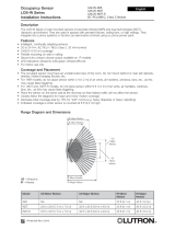
OCCUPANT SENSOR
LOS-W SERIES
Installation Instructions Please Read
DESCRIPTION
The LOS-W Series of wall-mounted sensors incorporate infrared (WIR) and dual technologies--ultrasonic
and infrared (WDT). They are used in spaces with pendant fixtures, ceiling fans, or high ceilings. They inte-
grate into Lutron systems or function as stand-alone controls using a Lutron power pack.
FEA
TURES
• Intelligent, continually adapting sensors
• 20-24 V , Class 2 (PELV) low voltage, 33 mA nominal
• 1600 sq.ft. coverage
• Flexible mounting on wall or ceiling
• Second dry contact closure output available on R models
• LED indicators: Ultrasonic (US)-green, Infrared (IR)-red
• For indoor use only
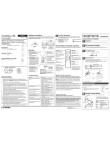
COVERAGE AND PLACEMENT
• The occupant sensor must have an unobstructed view of the room entrance. Do not mount behind or near
tall cabinets, shelves, indirect hanging fixtures, etc.
• Keep the occupant sensor away from air flow.
• Place the sensor on the same wall as the doorway so that hallway traffic will not affect the sensor.
• Closely follow the diagrams for major and minor motion coverage.
• Decrease total coverage area by 15% for “soft” rooms (for example, heavy draperies or heavy carpeting).
• Indicated coverage is when sensor is mounted at 8 ft. high.
Model US Minor Dims. US Major Dims. IR Minor IR Major
WIR NA NA 20 (6.1) 40 (12.2)
WDT 23 x 23 (7.0 x 7.0) 32 x 32 (9.8 x 9.8) 20 (6.1) 40 (12.2)
WDT-R 23 x 23 (7.0 x 7.0) 32 x 32 (9.8 x 9.8) 20 (6.1) 40 (12.2)
US
Minor
Motion
IR Minor Motion
Motion Detection Ranges
Dimensions and Ranges are in feet (m).
US Major Motion
US Minor Motion
IR Major Motion
US
Major
Motion
LOS-WIR
LOS-WDT
LOS-WDT-R
Class 2 (PELV) Devices
English
R
LIMITED WARRANTY
Lutron will, at its option, repair or replace any unit that is defective in materials or manufacture within one year after
purchase. For warranty service, return unit to place of purchase or mail to Lutron at 7200 Suter Rd., Coopersburg, PA
18036-1299, postage pre-paid.
This warranty is in lieu of all other express warranties, and the implied warranty of merchantability is limited to one year
from purchase. This warranty does not cover the cost of installation, removal or reinstallation, or damage resulting
from misuse, abuse, or improper or incorrect repair, or damage from improper wiring or installation. This warranty
does not cover incidental or consequential damages. Lutron’s liability on any claim for damages arising out of or in
connection with the manufacture, sale, installation, delivery, or use of the unit shall never exceed the purchase price of
the unit.
This warranty gives you specific legal rights, and you may also have other rights which vary from state to state. Some
states do not allow limitations on how long an implied warranty lasts, so the above limitation may not apply to you.
Some states do not allow the exclusion or limitation of incidental or consequential damages, so the above limitation or
exclusion may not apply to you.
Lutron and the sunburst logo are registered trademarks of Lutron Electronics Co., Inc. © 2005.
World Headquarters
Lutron Electronics Co., Inc.
7200 Suter Road
Coopersburg, PA 18036
TEL +1-610-282-3800
FAX +1-610-282-1243
Internet: www.lutron.com
E-mail: [email protected]
Lutron Electronics Co., Inc.
Made and printed in U.S.A.
P/N 031-259 Rev. A 6/05
Single Sensor to System
2 or More Sensors to System
Lighting
control
system
Red (+20-24 V )
Blue (signal)
Black (common)
Red (+20-24 V )
Blue (signal)
Black (common)
Lighting
control
system
To additional sensors, maximum
determined by lighting controller
120/277/347 V 60 Hz;
230 V 50/60 Hz
Neutral
Power Pack
Manual switch
off (optional)
Load
Note: Maximum 3 occupant sensors.
Red (+20-24 V )
Blue (signal)
Black
(common)
Black
White
Red
Red
1 to 3 Sensors with Power Pack
Switching Multiple Loads with Auxiliary Power Packs
Hot
Manual switch off (optional)
Load
Load
Power Pack
Auxiliary
Power Pack
Red
Red
Red (+20-24 V )
Black
(common)
Note: Maximum of 3 devices total
(occupant sensors and auxiliary power packs) can be connected to a power pack.
Neutral
Hot
Blue (signal)
Black
White
Red
Red
TROUBLESHOOTING
Problem Possible Cause Test Result
Lights stay on Constant noise Reduce red knob by 15%; Move sensor
remove noise source
Lights on too long Timer setting too high Check switch settings Typical setting is 8 min.
Hallway traffic Infrared sensor Put in timer test mode; Move sensor
turns lights on “sees” into hallway walk along hallway
Sensor not responding Unit is locked up -- Cycle power to sensor
WIRING DIAGRAMS (continued)
R
120/277/
347 V
60 Hz;
230 V
50/60 Hz

SENSOR ADJUSTMENTS
Factory Settings
Adjusting the “Lights Not On”
Level: LOS-WDT-R only
1. Ensure that the ambient light is at the desired level.
2. Place sensor in Test Mode: Press and release black pushbutton.
3. Set photo cell: Turn the blue knob full clockwise (lights on no matter how bright the natural light is), then about 30
degrees counterclockwise.
4. Check for Lights-Out: Move from underneath the sensor, and remain still until the lights turn off. Move around normally
to turn the light on.
5. Adjust to desired level: If lights turn on, adjust the blue knob another 30 degrees counterclockwise and repeat step 3
until the lights remain off.
Note: Set blue knob to 100% to disable photo cell functionality and leave secondary dry contact closure output func-
tionality intact.
Note: Not all models have every knob.
Control Settings (Blue Knob): LOS-WDT-R only
0 1000
0 1000
0 1000
Minimum (low):
Lights will never come on, even though
room is occupied.
Maximum (high):
Photo cell has no effect on operation
(factory setting).
Normal:
200 to 600 LUX is normal range.
Lighting
Control
system
Red (+20-24 V )
Gray (control: occupancy & photo cell signal)
Black (common)
Yellow/White (NO)
Black/White (NC)
Blue/White (Relay Common)
Choose wire based on functionality:
• Yellow/White: NO (normally open)
Open: Unoccupied
Closed: Occupied
• Black/White: NC (normally closed)
Open: Occupied
Closed: Unoccupied
Cap off unused wire.
WIRING DIAGRAMS
Relay Model Option: LOS-WDT-R only
R
A
B
Timer Test Mode
Push and Release:
8 sec. test timer
(resets to Normal
after 1 hour)
Push and Hold (flash):
Normal timer
Red: Infrared
75% default
Green: Ultrasonic
50% default
Blue: Photo cell
(R model only)
100% default
1 2 3 4
1 2 3 4
3
Wire Lengths (feet)
# Sensors 1 2 3 1 2 1
# Aux. PPs 0 0 0 1 1 2
22 AWG 750 375 250 375 250 250
20 AWG 1200 600 400 600 400 400
18 AWG 2400 1200 800 1200 800 800
Mounting to Wall or Ceiling Tile:
Redrill wiring routing hole
and (2) mounting holes
using Mounting Bracket
as template. Route wires
through wall and mount-
ing bracket. Secure
mounting bracket to
wall/ceiling tile using mounting screws, nuts, and wash-
ers (included).
Mounting in Acoustic Ceiling Tile:
Twist threaded mounting post onto
Mounting Bracket. Drill through ceiling tile
with assembly. Secure with washer and
nut. Route wiring through Mounting
Bracket and connect to wire harness.
Snap bracket cover in place to
conceal wiring and bracket.
Off (Default) On
Automatic (Normal) Manual lights on (Override)
Not used Not used
LED on (Normal) LED off
Retain Settings (Normal) Any change resets learned settings
Off On
OFF 8 OFF 4 ON 15 ON 30
OFF min. ON min. OFF min. ON min.
Auto Timer Adjust On Auto Timer Adjust Off
Auto Sensitivity Adjust On Auto Sensitivity Adjust Off
SENSOR
ADJUSTMENTS
Override Settings
Mounting Plate Dimensions
Measurements are in inches (mm)
2.25
(58)
3.35
(86)
2.5 (63)
.52 (13.3)
1 2 3 4
1 2 3 4
A
B
}} }
PRE-INSTALLATION
1. For installation by a qualified electrician in accordance with national and local codes and the following instructions.
2. For indoor use only.
3. CAUTION: RISK OF ELECTRIC SHOCK. Disconnect power before installing. Never wire energized electrical
components.
4. CAUTION: USE COPPER CONDUCTORS ONLY.
5. CAUTION: Do not connect this Class 2/PELV product to line voltage/mains cable.
6. Check to see that the device type and rating is suitable for the application.
7. Do not install if product or lens have any visible damage.
8. If moisture or condensation is evident, allow the product to dry completely before installation.
INST
ALLATION AND MOUNTING
}
2
Either Method:
Feed wiring harness through the back of the sensor body and out the exit slot. Snap sensor
onto mounting post. Plug wiring harness into connector on the left side (opposite exit slot)
and place wiring under wire tabs. Align sensor and tighten position locking screw.
R
Gray wire: logic with photo cell active:
Room First Occupied During Occupancy
Light level: Lights: Light level: Lights:
Below set value Turn on Falls below set value Turn on
Above set value Remain off Moves above set value Remain on
ON
ON
Blue: Cap off
/