Page is loading ...

INS #
IB505063EN 049-306 SURE-LITES
Installation Instructions for the Sure-Lites Lites SELA Architectural Emergency Light
with Self Diagnostics
WARNING
Risk of Fire/Electric Shock
If not qualified, consult an electrician.
WARNING
Risk of Electric Shock
Disconnect power at fuse or circuit breaker before
installing or servicing.
Important Safeguards
WHEN USING ELECTRICAL EQUIPMENT, BASIC SAFETY
PRECAUTIONS SHOULD ALWAYS BE OBSERVED INCLUDING
THE FOLLOWING.
1. READ AND FOLLOW ALL SAFETY INSTRUCTIONS
2. Do not use outdoors.
3. Do not use in hazardous locations, or near gas or electric
heaters.
4. Do not let power supply cords touch hot surfaces.
5. Use caution when servicing batteries. Battery acid can
cause burns to skin and eyes. If acid is spilled on skin or in
eyes, flush acid with fresh water and contact a physician
immediately.
6. Do not use this equipment for other than the intended use.
7. Installation is to be performed only by qualified personnel.
8. Install in accordance with National Electric Code and local
regulatory agency requirements.
9. The use of accessory equipment not recommended by the
manufacturer may cause an unsafe condition.
10. Equipment should be mounted in locations and at heights
where it will not readily be subjected to tampering by
unauthorized personnel.
11. SAVE THESE INSTRUCTIONS
MAX MOUNTING HEIGHT: 17 ft.
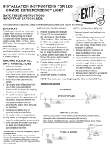
INSTALLATION
1. De-energize the circuit to which the fixture will be
connected.
2. Remove fixture assembly from back box provided. (See
Fig. 1).
3. Plan how wiring will be extended to the fixture. Knock
out the appropriate conduit KO and extend wiring to the
fixture.
4. If bar hanger installation is desired, proceed to step 6.
5. If installation without bar hangers is desired, remove the
bar hangers by removing the four 6-32 screws holding
the bar hanger brackets in place. The back box can now
be screwed or nailed directly to a stud or other suitable
surface. Proceed to step 8.
6. Bar hangers for this fixture are of interlocking design to
allow positioning of housing along entire length of bars.
Position bar hangers to the desired position between the
studs. Bar hangers may be shortened to fit 12” framing by
breaking at score lines (Hanger bar range is 8-24”). Pass
bar hangers through each end until the bars overlap, then
break off at score lines (no tools required and bar hangers
do not need to be removed from bracket). (See Fig. 2)
Secure hanger bars with nails or screws into studs.
7. Adjust position of back box on bar hangers as needed. To
secure back box in positon, crimp tabs on bracket over bar
hangers.
8. Retrieve fixture assembly.
9. Connect power supply and ground in accordance with
local codes. Connect the incoming wires to the fixture’s
power supply wires using the wire nuts provided. Connect
the white wire to neutral. Connect 277VAC line to Orange
lead or 120V line to Black lead, cap the unused lead. (See
Schematic).
10. Place the fixture assembly and wiring in the back box, and
secure to the fixture using long 6-32 screws. (See Fig. 1).
11. Remove the EZ Key. Lamps will light. Adjust the heads as
needed.
12.Energize AC supply. The test button should illuminate and
LED heads will illuminate briefly when the test button is
pushed or laser test is engaged.
13.Replace the EZ Key if the fixture will be de-energized for a
prolonged period of time.
14. Snap on the decorative cover, if desired (See Fig. 3).
Decorative cover is sold separately.
FLEXIBLE CONDUIT ONLY
X

Installation Instructions for the Sure-Lites SELA Architectural Emergency Light with Self Diagnostics
ACTIVATING TIME DELAY
The SELA series has an integrated time delay circuit that
allows them to remain in emergency mode 15 minutes after
power is restored. To activate the time delay, open the fixture
by unsnapping the fixture assembly cover from the fixture
assembly body (see Fig. 4) and then remove the jumper on the
circuit board labeled TDI/J1 (see Figure 5).
OPERATION
The Sure-Lites Self Diagnostics circuitry is continuously
monitoring your emergency fixture, and will signal any failure
through the 3 color indicator LED.
Initial Operation
When the unit is first powered up, it will go into a 24 hour fast
charge, indicated by the indicator LED pulsing green. Once the
unit has fully charged, it will perform a self-calibration, after
which the LED will change to steady green, indicating the unit
is fully charged and float charging the battery to maintain
readiness.
Automatic Testing
The unit will perform a battery capacity, lamp/LED, and charge
circuit test every 30 days for 30 seconds. During this time, the
indicator LED will change to a steady yellow. It will perform a
full battery capacity (90 minute) test once per year. During this
time, the indicator LED will change to a blinking yellow.
Manual Testing
• 10 Second “Installation” test – Press and release the test
button once during fast charge (blinking green) to initiate a 10
second quick test. The sign will switch to emergency mode for
10 seconds allowing the installer to verify proper installation of
the unit, and the LED indicator will turn solid yellow.
• 30 Second Test -Press and release the test button once during
float charge (steady green). The indicator LED will turn steady
yellow to indicate the unit is performing a 30 second test of the
batteries and lamps/LEDs.
• 90 Minute Test -Press and release the test button a second
time during a 30 second test (steady yellow) to change to a 90
minute test. During this test, the LED indicator will change to
blinking yellow, and the circuit will perform a full battery
capacity, charge circuit, and LED test.
• Canceling Test – Press and release the test button during the
90 minute test (flashing yellow) to return the fixture to its
original state (fast charge or float charge).
Laser Testing
The SELA is equipped with a Laser Test function, that allows the
unit to be manually tested without the need to physically press
the test button. Shining a laser pointer in the hole marked
“LASER TEST” on the bottom of the unit has the same effect as
a press and release of the test button.
Figure 4
Battery
Compartment
Cover
Figure 2
Bend Outwards
At Score Line
Score Lines
Figure 3
Snap On Decorative Cover (Sold Separately)
Snap Locations
Cross
Section
View
Fixture Assembly Cover
Fixture Assembly body
Battery
Figure 1
Wall Stud
Bar Hangers
Black Box
Fixture Assembly
EZ Key
2.125" #6-32 Screws

Installation Instructions for the Sure-Lites SELA Architectural Emergency Light with Self Diagnostics
© 2017 Eaton
All Rights Reserved
Printed in USA
Impreso en los EE. UU.
Publication No. IB505063EN
Eaton
1000 Eaton Boulevard
Cleveland, OH 44122
United States
Eaton.com
Eaton is a registered trademark.
All trademarks are property
of their respective owners.
Eaton es una marca comercial
registrada. Todas las marcas
comerciales son propiedad de sus
respectivos propietarios.
Warranties and Limitation of Liability
Please refer to www.eaton.com/LightingWarrantyTerms for our terms and conditions.
SCHEMATIC
ORANGE LEAD - TO 277VAC
BLACK LEAD - TO 120VAC
BATTERY
CHARGER/
DRIVER
PCB
TIME DELAY
JUMPER
LOCATION
WHITE LEAD - TO NEUTRAL
LED
HEADS
Clearing Failure Code
• A battery failure (LED two blink red) can be cleared by
replacing the battery. Disconnecting the battery and AC power
or performing a full 90 minute discharge will also reset the
error code. However, the error code will return if the battery is
faulty.
• Charge Circuit (LED three blink red) and lamp/LED failure
(LED four blink red) will clear when the unit successfully passes
a manual or automatic 30 second test.
Indicators
• LED Off - No power to unit or in emergency mode.
• LED Steady Green - Unit is fully charged and is float charging
the battery to maintain readiness.
• LED Green Pulse - Unit is in a 24 hour fast charge of
the battery.
• LED Two Blink Red - Battery has failed a capacity test or the
battery is disconnected. See “Clearing Failure Codes” above.
• LED Three Blink Red - Battery charge circuit has failed. See
“Clearing Failure Codes” above.
• LED Four Blink Red - Lamps have burned out, or on an EXIT/
Combo, 50% or more of the LEDs have failed. See “Clearing
Failure Codes” above.
• LED Steady Yellow - 30 second test or 10 second quick test
(Fast Charge only).
• LED Blinking Yellow - 90 minute test.
MAINTENANCE
None required. Replace the batteries as needed according
to ambient conditions. However, we recommend that the
equipment be tested regularly in accordance with local codes.
NOTE: Servicing of any parts should be performed by qualified
personnel. Only use replacement parts supplied by Eaton
Lighting.
CAUTION: This equipment is furnished with a sophisticated low
voltage battery dropout circuit to protect the battery from over
discharge after its useful output has been used. Allow 24 hours
recharge time after installation or power failure for 90 minute
testing.
TROUBLE SHOOTING GUIDE
If LED heads or charge indicator LED does not illuminate, check
the following:
1. Check AC supply – verify that unit has 24 hour AC supply.
2. Unit is shorted or battery is not connected.
3. Battery discharged. Permit unit to charge for 24 hours and
then re-test.
4. If following the above trouble shooting hints does not
solve your problem, contact your local Eaton Lighting
representative for assistance.
Figure 5
Time Delay Jumper Pin Location
/