Page is loading ...

INSTRUCTIONS FOR EMERGENCY LIGHTING FIXTURE
INSTRUCTIONS FOR EMERGENCY LIGHTING FIXTUREINSTRUCTIONS FOR EMERGENCY LIGHTING FIXTURE
INSTRUCTIONS FOR EMERGENCY LIGHTING FIXTURE R
R R
R-
--
-1SDT
1SDT1SDT
1SDT
IMPORTANT
IMPORTANTIMPORTANT
IMPORTANT:
::
:
Battery in this unit may not be full
charged after electricity is connected to unit, let battery charge
up for at least 24 hours. Then normal operation of this unit
should take effect. To check, press the “TEST” button. The
light inside the unit should turn on.
IMPORTANT SAFEGUARDS
IMPORTANT SAFEGUARDSIMPORTANT SAFEGUARDS
IMPORTANT SAFEGUARDS:
When using electrical equipment, basic safety precautions should always be followed including the following:
READ AND FOLLOW ALL SAFETY INSTRUCTIONS
1. Do not use outdoors.
2. Equipment should be mounted in locations at heights where it will not be subject to tampering by
unauthorized personnel.
3. Do not mount near gas or electric heaters.
4. The use of accessory equipment is not recommend by the manufacturer may cause an unsafe condition.
5. Do not use this equipment of other than its intended use.
6. Servicing of this equipment should be performed by qualified personnel.
7. Disconnect AC power before servicing.
SAVE THE ABOVE INSTRUCTIONS
FLEXIBLE CONDUIT ONLY
INSTALLATION (J
INSTALLATION (JINSTALLATION (J
INSTALLATION (J-
--
-BOX MOUNTING)
BOX MOUNTING)BOX MOUNTING)
BOX MOUNTING):
::
:
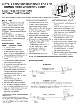
1. Feed fixture leads through back plate and connect AC power supply (Fig. A).
2. Connect wires through J-Box. Mount back plate on J-Box and secure with screws.
3. Connect battery only after continuous AC power can be provided to the unit (Fig. B).
4. Align snaps and push housing directly onto main bottom case (Fig. C).Apply continuous AC power and
press “TEST” button to check light.
INSTALLATION (CONDUIT)
INSTALLATION (CONDUIT)INSTALLATION (CONDUIT)
INSTALLATION (CONDUIT):
::
:
1. Secure back plate to wall surface. Route wires through hole in conduit flange and make conduit connection.
2. Connect battery only after continuous AC power can be provided to the unit (Fig. B).
3. Align snaps and push housing directly onto back plate (Fig. C). Apply continuous AC power and press
“TEST” button to check light.

SELF
SELFSELF
SELF-
--
-DIAGNOSTICS TESTING:
DIAGNOSTICS TESTING:DIAGNOSTICS TESTING:
DIAGNOSTICS TESTING:
1) NORMAL OPERATION
When unit is functioning properly with A.C. power supplied, the status indicator will be green.
2) TESTING
The exit performs two types of tests, Contingency and Non-Contingency.
The contingency testing includes “Battery Disconnected Mode” and “Lamp Failure Mode”. When the Battery is
disconnected, the indicator would indicate as Red (Steady). When the Lamp fails, the indicator would indicate as Red
(Blinking - three times).
The Non-Contingency test is for testing the Battery for its “discharging” and “recharging” capacity. A 15 minute battery
discharge test is performed every 30 days to check for the normal operation of the battery and the unit. Also a full 90
minute discharge test is performed once a year to confirm the same. When the battery is in discharging mode, the LED
indicator would be a flashing Green (Three/ Four Pulses). Upon completion of the test and after 24 hours battery charging
(Indicator on Red and Green flashing), the status indicator will return to either Green (Steady) indicating a properly
functioning unit or Red (Double Pulse) to show a battery failure. The following table shows the status indication.
FUNCTION LED INDICATION
Exit is in Emergency Mode Off
Exit is in Normal Mode Green (Steady)
Battery Disconnected Red (Steady)
Lamp Failure Red (Flashing 4 times)
Battery Fast Charging Red and Green (Flashing Alternately)
Battery Failure* Red (Flashing 2 times)
30 Second Battery Discharging Mode Green (Flashing 1 time)
15 Minute Battery Discharging Mode** Green (Flashing 2 times)
90 Minute Battery Discharging Mode*** Green (Flashing 3 times)
* = Happens only after battery discharges once in every 30 days or 1 year.
** = Occurs once in every 30 days. *** = Occurs once in a Year.
MANUAL TESTING
MANUAL TESTINGMANUAL TESTING
MANUAL TESTING:
Battery and Lamp test may be manually initiated by pressing the manual test switch. Once the test switch is
pressed, the unit would be reset and the date of battery self-testing would start counting again.
ACTION REACTION AND LED INDICATION
Press test button once (within 2 seconds) 30-second test; Green light - Single blinking
Press test button 2 times (within 2 seconds) 15-minute test; Green light - Double blinking
Press test button 3 times (within 2 seconds) 90-minute test; Green light - Triple blinking
OPERATION
OPERATIONOPERATION
OPERATION:
::
:
During an electrical power failure, the lamps will automatically come on for a minimum of 90 minutes. To test this unit,
the battery needs to be charged initially for 2 hours before depressing the test switch. On pressing the test switch, the
emergency lamps will illuminate. When the switch is released, the lamps will turn off.
/