SolaX Power X3 Three-Phase EPS Box Installation guide

Type
Installation guide

SolaX Power X3 Three-Phase EPS Box allows for easy integration of an EPS (Emergency Power Supply) into a three-phase electrical system. It simplifies the connection process by requiring only 13 wires to complete the steering circuit, enhancing both operational ease and safety. The box is compatible with three-phase EPS change-over applications and provides power steering functionality for users.

SolaX Power X3 Three-Phase EPS Box allows for easy integration of an EPS (Emergency Power Supply) into a three-phase electrical system. It simplifies the connection process by requiring only 13 wires to complete the steering circuit, enhancing both operational ease and safety. The box is compatible with three-phase EPS change-over applications and provides power steering functionality for users.

170mm
300mm
220mm
Three-Phase EPS Box
Quick Installation Guide
1. Introduction
2. Overview
3. Preparation
3.1Packing List Checking
Before installation, make sure that nothing inside the package is damaged.
The following items should be inside the package.
Before you start, get the following tools ready.
3.2 Tools
Three-phase EPS Box integrates two contactors which
provide power steering for users. It is compatible with
Three-phase EPS change-over application. Configured
with Three-phase EPS Box, customers need to connect 13
wires to complete the steering circuit. It can simplify the
operation and improve security.
01
4. Mounting
Step 1:
Make sure the installation site does not expose to direct sunlight. Then install the four cushion
blocks on Three-phase EPS Box with self-tapping screws.
Step 2:
Use Three-phase EPS Box with cushion blocks as a template to mark the four holes’ position on
the wall with marker pen.
02
-Drill holes with 6 drillΦ
-Depth : at least 50mm
-Τighten the expansion tubes
Drill holes with Install Φ6 driller carefully, make sure the holes are deep enough for installing.
the expansion tubes through cushion blocks into the holes and tighten them.
Install the expansion screws with screwdriver to fix the Three-phase EPS Box.
Step 3:
Step 4:
self-tapping screws
cushion blocks
mark position
1 EPS
3 Load
2 Grid
expansion tubes
X 4
cushion blocks
X 4
ƒ
self-tapping
screws X 4
cold pressed
terminals X15
Silicone sleeves
X15
Diagonal plier
Rubber hammer
Φ6 driller
Marker pen
Manual wrench
Crimping plier
Philips screwdriver
Slotted screwdriver
expansion screws
X 4
1
EPS Box
EPS Load
Object Description
614.00213.03
6. Technical Parameters
04
03
5. Wiring Connection
Grid
Max.AC input current (A)
Rated AC voltage ( V )
Rated AC frequency (Hz)
EPS
Max.EPS input current (A)
Rated EPS voltage ( V )
Rated EPS frequency (Hz)
3x63
3/N/PE~400/230
50 / 60
50 / 60
Load
Genaral Data
Operating Temperature range ( )
Dimension (mm)
Weight (kg)
Rated output current(A), on grid mode
Rated output current(A), EPS mode
Rated Grid Voltage( V )
3x63*
300x220x170
4.85
-20~+60
Rated Grid Frequency(Hz) 50/60
3x63*
3x63
3/N/PE~400/230
3/N/PE~400/230
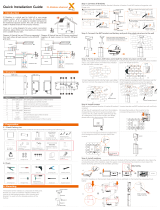
Overview of Three-phase EPS Box
For EU For AU
5.1 Wires making
Prepare wires as below. Use the diagonal plier to trip
15mm of insulation from side of the wire.
Insert wire into cable gland, then insert the
end of wire into cold pressed terminal and
tighten it.
For AU x1 pcs
15mm
GND
For EU X1 pcs
15mm
15mm
5.2 Grid-Wires Connection
Use the manual wrench to screw off the cap on cable nut, then insert Grid-L wires and Grid-N wires
into the ports (L1,L2,L3,L4) of contactor A through the cable nut and tighten them with screwdriver.
Please prevent other wires from getting loose during operation.
Top View
L wire X9 pcs
N wire X3 pcs
If AWG-10 wires are used, please pass the wires through the silicone
sleeves to aviod leakage at the insertions.
In EU, insert GND wire into port of contactor (B: L4) through the cable nut and tighten it with screwdriver.
In AU, insert N wire into ports of contactor(A: L4&B: L4) .
5.5 Earth-Wire Connection
For EU For AU
Please make sure all wires are tightened. Wire connection in Three-phase EPS-Box.
5.6 Checking
* : The output current will be reduced when the operating temperature exceeds 40.
At 50, the output current drops to 95% . At 60,itdropsto80%.
Screw off the cap on cable nut, then insert Load-L wires and Load-N wires into ports (T1, T2, T3, T4)
of contactor C through the cable nut and tighten them with screwdriver.
5.4 Load-Wires Connection
Screw off the cap on cable nut, then insert EPS-L wires and EPS-N wires into ports (L1,L2,L3,L4)
of contactor B through the cable nut and tighten them with screwdriver.
5.3 EPS-Wires Connection
Top View
Top View
cable nut
cap
contactor A
contactor B
contactor C
Grid wires
contactor C
cable nut
cap contactor B
contactor A
EPS wires
to GRID
to EPS port of inverter
to Load
to E-BAR
to GRID
to EPS port of inverter
to Load
For AU
For EU
N wire
contactor B
cap
cable nut
load wires
contactor C
contactor A
Left View
Grid-L
Grid-N
Left View
Grid-L
Grid-N
EPS-L
EPS-N
Load-L Load-N
Right View
  • Page 1 1
  • Page 2 2

SolaX Power X3 Three-Phase EPS Box Installation guide

Type
Installation guide

SolaX Power X3 Three-Phase EPS Box allows for easy integration of an EPS (Emergency Power Supply) into a three-phase electrical system. It simplifies the connection process by requiring only 13 wires to complete the steering circuit, enhancing both operational ease and safety. The box is compatible with three-phase EPS change-over applications and provides power steering functionality for users.

Ask a question and I''ll find the answer in the document

Finding information in a document is now easier with AI