Moxa DA-681 Series User manual

Category
Thin clients
Type
User manual
DA-681 Series Embedded Computer
Hardware Users Manual
Fifth Edition, January 2010
www.moxa.com/product
© 2010 Moxa Inc. All rights reserved.
Reproduction without permission is prohibited.
DA-681 Series Embedded Computer
Hardware User’s Manual
Any software described in this manual is furnished under a license agreement and may be used only in
accordance with the terms of that agreement.
Copyright Notice
Copyright © 2010 Moxa Inc.
All rights reserved.
Reproduction without permission is prohibited.
Trademarks
MOXA is a registered trademark of Moxa Inc.
All other trademarks or registered marks in this manual belong to their respective manufacturers.
Disclaimer
Information in this document is subject to change without notice and does not represent a commitment on the
part of Moxa.
Moxa provides this document “as is,” without warranty of any kind, either expressed or implied, including, but
not limited to, its particular purpose. Moxa reserves the right to make improvements and/or changes to this
manual, or to the products and/or the programs described in this manual, at any time.
Information provided in this manual is intended to be accurate and reliable. However, Moxa assumes no
responsibility for its use, or for any infringements on the rights of third parties that may result from its use.
This product might include unintentional technical or typographical errors. Changes are periodically made to the
information herein to correct such errors, and these changes are incorporated into new editions of the
publication.
Technical Support Contact Information
www.moxa.com/support
Moxa Americas:
Toll-free: 1-888-669-2872
Tel: +1-714-528-6777
Fax: +1-714-528-6778
Moxa China (Shanghai office)
:
Toll-free: 800-820-5036
Tel: +86-21-5258-9955
Fax: +86-10-6872-3958
Moxa Europe
:
Tel: +49-89-3 70 03 99-0
Fax: +49-89-3 70 03 99-99
Moxa Asia-Pacific
:
Tel: +886-2-8919-1230
Fax: +886-2-8919-1231
Table of Contents
Chapter 1 Introduction..................................................................................................1-1
Overview.................................................................................................................................. 1-2
Model Descriptions and Package Checklist............................................................................. 1-2
Appearance .............................................................................................................................. 1-3
Dimensions .............................................................................................................................. 1-4
Features.................................................................................................................................... 1-4
Hardware Block Diagram ........................................................................................................ 1-5
DA-681 Basic System ................................................................................................ 1-5
Hardware Specifications .......................................................................................................... 1-6
Non-standard Baudrates........................................................................................................... 1-8
Chapter 2 Hardware Installation...................................................................................2-1
Placement Options ................................................................................................................... 2-2
Desktop....................................................................................................................... 2-2
Rack mounting ........................................................................................................... 2-2
Wiring Requirements ............................................................................................................... 2-4
Connecting the Power .............................................................................................................. 2-5
Wiring the Power Inputs .......................................................................................................... 2-6
Power Input Wiring Description .............................................................................................. 2-9
HIPOT (Dielectric Strength) Testing ......................................................................................2-11
Reset Button........................................................................................................................... 2-12
Front Panel LED .................................................................................................................... 2-12
Connecting to a Display......................................................................................................... 2-13
Connecting a PS/2 Keyboard and Mouse............................................................................... 2-13
Connecting USB Devices ...................................................................................................... 2-14
LAN Ports.............................................................................................................................. 2-14
Upgrading the Memory Module ............................................................................................ 2-16
Installing a CompactFlash Card............................................................................................. 2-18
Installing a SATA Hard Disk.................................................................................................. 2-19
Chapter 3 BIOS Setup ...................................................................................................3-1
Entering the BIOS Setup Utility .............................................................................................. 3-2
Modifying the BIOS Main Settings ......................................................................................... 3-3
Basic Configuration.................................................................................................... 3-3
System Security.......................................................................................................... 3-3
Advanced Settings ................................................................................................................... 3-4
Hard Disk Boot Priority.............................................................................................. 3-4
Advanced BIOS Features ........................................................................................... 3-5
CPU Features.............................................................................................................. 3-5
Advanced Chipset Settings......................................................................................... 3-7
PnP/PCI Configurations ............................................................................................. 3-8
Frequency/Voltage Control ........................................................................................ 3-9
Peripherals ............................................................................................................................... 3-9
OnChip IDE Device ................................................................................................. 3-10
Onboard Device........................................................................................................ 3-11
Onboard I/O Chip Setup........................................................................................... 3-12
Power ..................................................................................................................................... 3-13
Wake Up Control...................................................................................................... 3-13
Hardware Monitor.................................................................................................................. 3-14
Load Defaults......................................................................................................................... 3-15
Exiting the BIOS Setup.......................................................................................................... 3-16
Upgrading the BIOS .............................................................................................................. 3-17
Appendix A Safety Installation Instructions..................................................................A-1
Appendix B Regulatory Statement Approval ................................................................B-1
1
1
Chapter 1 Introduction
Thank you for purchasing the Moxa DA-681 series x86-based industrial ready-to-run embedded
computer.
This manual introduces the hardware installation, connector interfaces and BIOS setup of the
DA-681. For software configuration and management, please refer to the user’s manual for your
operating system.
This chapter covers the following topics:
Overview
Model Descriptions and Package Checklist
Appearance
Dimensions
Features
Hardware Block Diagram
¾ DA-681 Basic System
Hardware Specifications
Non-standard Baudrates
DA-681 Series Hardware User’s Manual Introduction
Overview
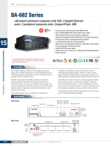
The DA-681 computer is based on the Intel x86 processor and supports VGA, 6 Ethernet ports, 4
RS-232 and 8 RS-485 serial ports with optical isolation, CompactFlash, and USB. The DA-681
comes in a standard 19-inch, 1U high form factor, making it an ideal platform for industrial
applications.
With its robust design, the DA-681 is suitable for industrial automation applications that require
standard 19-inch rackmount solutions, such as power automation, transportation, and oil and gas.
Another plus is that the serial ports come with 2 KV optical isolation protection to guarantee
communication reliability in harsh industrial environments.
Moreover, the DPP-T models are in full compliance with IEC 61850-3 standards to meet the
demands of power substation automation.
The DA-681 runs Linux, WinCE 6.0, or Windows XP Embedded (pre-installed), providing a
friendly environment for developing sophisticated application software. The great software support
that Moxa provides makes the programmer’s job easier, and helps programmers develop bug-free
code quickly and at a lower cost.
Model Descriptions and Package Checklist
The DA-681 Series includes the following models:
y DA-681-I-SP-CE:
x86 Ready-to-Run Rackmount Computer with VGA, 6 Ethernet, 4 RS-232, 8 RS-485,
CompactFlash, SATA, USB, Single Power, WinCE 6.0
y DA-681-I-SP-XPE:
x86 Ready-to-Run Rackmount Computer with VGA, 6 Ethernet, 4 RS-232, 8 RS-485,
CompactFlash, SATA, USB, Single Power, WinXPe SP2
y DA-681-I-SP-LX:
x86 Ready-to-Run Rackmount Computer with VGA, 6 Ethernet, 4 RS-232, 8 RS-485,
CompactFlash, SATA, USB, Single Power, Linux 2.6
y DA-681-I-DP-CE:
x86 Ready-to-Run Rackmount Computer with VGA, 6 Ethernet, 4 RS-232, 8 RS-485,
CompactFlash, SATA, USB, Dual Power, WinCE 6.0
y DA-681-I-DP-XPE:
x86 Ready-to-Run Rackmount Computer with VGA, 6 Ethernet, 4 RS-232, 8 RS-485,
CompactFlash, SATA, USB, Dual Power, WinXPe SP2
y DA-681-I-DP-LX:
x86 Ready-to-Run Rackmount Computer with VGA, 6 Ethernet, 4 RS-232, 8 RS-485,
CompactFlash, SATA, USB, Dual Power, Linux 2.6
y DA-681-I-DPP-T-CE:
IEC 61850-3 certified x86 Ready-to-Run Rackmount Computer with VGA, 6 Ethernet, 4
RS-232, 8 RS-485, CompactFlash, SATA, USB, Dual Power, WinCE 6.0
y DA-681-I-DPP-T-XPE:
IEC 61850-3 certified x86 Ready-to-Run Rackmount Computer with VGA, 6 Ethernet, 4
RS-232, 8 RS-485, CompactFlash, SATA, USB, Dual Power, WinXPe SP2
y DA-681-I-DPP-T-LX:
IEC 61850-3 certified x86 Ready-to-Run Rackmount Computer with VGA, 6 Ethernet, 4
RS-232, 8 RS-485, CompactFlash, SATA, USB, Dual Power, Linux 2.6
1-2
DA-681 Series Hardware User’s Manual Introduction
Each model is shipped with following standard items:
y 1 DA-681 Embedded Computer
y Quick Installation Guide
y Documentation & Software CD
y Ethernet Cable: RJ45 to RJ45 cross-over cable, 100 cm
y Product Warranty Statement
Appearance
Front View
Power Fail 2
Power Fail 1
RS-232 RS-485
LED Indicators
LAN
Power
Storage
19-inch
Rackmount Ear
LED Indicators
LED Indicators
Rear View
19-inch
Rackmount Ear
10/100 Mbps Ethernet x 6
RS-232 Serial Port x 4, DB9
RS-485 Serial Port x 8,
Terminal Block
Reset Button
VGA PS/2
USB 2.0
Host x 2
Power Input 1
Power Input 2
Power Switch
1-3
DA-681 Series Hardware User’s Manual Introduction
Dimensions
16.75
480
11.9
462
440
31.80
6.3
44
315
337
30
30
15
Features
The DA-681 Basic System has the following features:
y IEC 61850-3 certified for power substation automation systems (DPP-T models only)
y Intel Celeron M 1 GHz processor with 400 MHz FSB
y 1 x 200-pin DDR2 SODIMM socket, supporting DDR2 400 up to 1GB (512 Mb built-in)
y Six 10/100 Mbps Ethernet ports
y 1 CompactFlash socket, 1 IDE and serial ATA-150 connectors for storage expansion
y USB 2.0 ports for high speed peripherals
y 4 isolated RS-232 and 8 isolated RS-485 ports
y Serial port speed from 50 to 921.6 Kbps, supporting nonstandard baudrates
y Specific design for heat dissipation
y Embedded Linux, WinCE 6.0, or WinXPe platform
y 19-inch Rackmount model, 1U high
y Wide temperature models available (DPP-T models only)
y 100-240 VAC/VDC power input (Dual Power models offer power redundancy function)
y Fan-less design
1-4
DA-681 Series Hardware User’s Manual Introduction
ATTENTION
Refer to the “Non-standard Baudrates” section for instructions on how to calculate which
baudrates are supported.
Hardware Block Diagram
DA-681 Basic System
Power
RTC
Watch Dog
Timer
VGA
Intel Celeron
M 1GHz CPU
DDR2
SO-DIMM
Intel ICH6M South Bridge
PS/2
KB/Mouse
Super
I/O
BIOS
USB1
USB2
LAN1
LAN2
LAN3
LAN4
LAN5
LAN6
MU860 MU860
Flash DOM
CF Socket
SATA
1
Intel 910GMLE North Bridge
RS-485 x8RS-232 x 4
234 12345678
1-5
DA-681 Series Hardware User’s Manual Introduction
Hardware Specifications
DA-681-CE DA-681-LX DA-681-XPE
Computer
CPU Intel Celeron M 1 GHz processor
OS (pre-installed) WinCE 6.0 Linux 2.6 Windows XP
Embedded SP3
System Chipset Intel 910GMLE + ICH6M chipset
FSB 400 MHz
BIOS 4 mega-bit Flash BIOS, PCI Plug & Play, ACPI function support
System Memory 1 x 200-pin DDR2 SODIMM socket supporting DDR2 400; up to 1
GB max. (512 MB built-in)
DOM: 1 GB (2 GB for DA-681-XPE) industrial DOM onboard to store OS
via IDE interface
HDD Support SATA connector for HDD expansion
CompactFlash CompactFlash Type-I/II socket available for storage expansion with
DMA mode support
Other Peripherals
USB USB 2.0 compliant hosts x 2, Type A connector, supports system boot
up
KB/MS 1 PS/2 interface, support standard PS/2 keyboard and PS/2 mouse via
Y-type cable (0ptional)
Display
Graphics Controller Integrated graphics with built-in Intel 910GMLE, and built-in Intel
extreme Graphics 2 technology
Display Memory Dynamic video memory (shares up to 32 MB of system memory)
Display Interface CRT Interface for VGA output (DB15 female connector)
Resolution CRT display mode with pixel resolution up to 2048 x 1536 at 75Hz
Ethernet Interface
LAN Auto-sensing 10/100 Mbps Ethernet x 6, using Realtek RTL8110SC
Controller
Magnetic Isolation
Protection
1.5 KV built-in
Serial Interface
Number of Ports RS-232 x 4, RS-485 x 8
Serial Standards RS-232, RS-485
Connectors RS-232: DB9 connector, RS-485: terminal block
ESD protection 15 KV for all signals
Optical Isolation
Protection
2 KV
Serial Communication Parameters
Data Bits 5, 6, 7, 8
Stop Bits 1, 1.5, 2
Parity None, Even, Odd, Space, Mark
1-6
DA-681 Series Hardware User’s Manual Introduction
Flow Control RTS/CTS, XON/XOFF, ADDC™ (automatic data direction control)
for RS-485
Baudrate 50 bps to 921.6 Kbps (non-standard baudrates supported; see next
page for details)
Serial Signals
RS-232 TxD, RxD, DTR, DSR, RTS, CTS, DCD, GND
RS-485-2w Data+, Data-, GND
LEDs
System Power x 1, Storage x 1, Power 1 Fail x 1, Power 2 Fail x 1
LAN 10 Mbps x 6, 100 Mbps x 6
Serial RS-232 TX x 4, RX x 4, RS-485 TX x 8, RX x 8
Physical Characteristics
Enclosure SECC sheet metal (1 mm)
Weight 4.5 kg for SP and DPP models; 4.7 kg for DPP-T models
Dimensions 440 x 253 x 45 mm (17.32 x 9.96 x 1.77 in)
Mounting Standard 19-inch rackmount
Switches and Buttons
Reset Button To reset system hardware (on rear panel)
Environmental Limits
Operating Temperature -10 to 60°C (14 to 140°F) for SP and DP models
-40 to 75°C (-40 to 167°F) for DPP-T models
Operating Humidity 5 to 95% RH
Storage Temperature -20 to 80°C (4 to 176°F) for SP and DP models
-40 to 85°C (-40 to 185°F) for DPP-T models
Anti-Vibration 7 mm (2-9 Hz), 20 m/ s
2
(9-200 Hz), 15 m/ s
2
(200-500 Hz) @
IEC-61850-3, IEC 60870-2-2/Cm/(3M6)/(4M6), sine wave, 2-500 Hz,
1 Oct/min, 10 Cycles, 2 hrs 40 mins per axis
Anti-Shock 300 m/s
2
@ IEC-61850-3, IEC 60870-2-2/Cm/(3M6)/(4M6), half sine
wave, 11 ms
Power Requirements
Input Voltage 100 to 240 VAC/VDC auto-ranging (47 to 63 Hz for AC input), single
power for SP models, dual power for DP and DDP models; dual
power models offer power redundancy function
Power Consumption 50W
Input Rating 100-240VAC, 47-63Hz, 1.0A-0.5A
Regulatory Approvals
EMC CE (EN55022, EN61000-3-2, EN61000-3-3,
EN55024), FCC (Part 15 Subpart B, CISPR 22 Class ), CCC
(GB9254, GB 17625.1), IEC 61850-3 (DPP-T models only)
Safety UL/cUL (UL60950-1, CSA C22.2 No. 60950-1-03), LVD
(EN60950-1), CCC (GB4943)
Reliability
Alert Tools Built-in buzzer and RTC (real-time clock) with battery lithium backup
Warranty
Warranty Period 3 years
Details: See www.moxa.com/warranty
1-7
DA-681 Series Hardware User’s Manual Introduction
Non-standard Baudrates
Moxa’s UART ASIC, supports most non-standard baudrates in the range 50 bps to 921.6 Kbps. In
fact, supported baudrates are much denser towards the lower values. For example, no baudrates are
supported between the integers 5320 and 5323, but 49 baudrates are supported between the
integers 387 and 388. Of course this is the way it should be, since serial devices that require using
non-standard baudrates generally use slower baudrates.
Before using a serial device that requires using a non-standard baudrate, you must first check that
the DA-681 supports a baudrate within the tolerance specified by the serial device manufacturer.
Use the following formula to calculate which baudrates are supported by the DA-283:
(A) Baudrate = 921600/(N+M/8) bps, for N = 1, 2, …, 18431, M = 0, 1, 2, …, 7
or
(B) Baudrate = 8 x 921600/K bps, for K = 8, 9, …, 147456
If you are a programmer and you need to write a driver for your serial device, then you may need
to use formula A. If you have a serial device that requires using a non-standard baudrate, then you
can use formula B to determine if the DA-681 supports a baudrate within the tolerance specified
by the serial device manufacturer.
Example
: Your serial device requires using a baudrate of 5340 bps and has a tolerance of 2 bps.
Can the DA-681 be used with this device?
Solution
: Set formula B to the desired baudrate and then solve for K.
8 x 912600/K = 5338 ==> K = 1367.703259…
This shows that the supported baudrate closest to 5340 comes from setting K=1367 or K=1368.
K=1368 ==> Baudrate1 = 5336.842105...
K=1367 ==> Baudrate2 = 5340.746159…
Since 5338 – Baudrate1 < 2, we can see that the DA-681 supports the serial device.
Note that we can use formula A to generate the so-called “standard” baudrates, which come from
setting M=0, and setting N equal to certain integers.
Standard Baudrates
Baudrate N M Baudrate N M
921600 1 0 4800 192 0
460800 2 0 2400 384 0
230400 4 0 1800 512 0
115200 8 0 1200 768 0
57600 16 0 600 1536 0
38400 24 0 300 3072 0
19200 48 0 150 6144 0
9600 96 0 75 12288 0
7200 128 0 50 18432 0
1-8
DA-681 Series Hardware User’s Manual Introduction
WARNING
Communication between a serial device and a Moxa UART port may not work correctly if the
serial device uses a baudrate that it not within the correct tolerance of a baudrate calculated from
either formula A or formula B.
1-9
2
2
Chapter 2 Hardware Installation
The DA-681 Series of embedded computers are compact and rugged, making them suitable for
industrial applications. The LED indicators allow users to monitor performance and identify
trouble spots quickly, and multiple ports are provided for connecting a variety of different devices.
The DA-681 embedded computers come with a reliable and stable hardware platform that lets you
devote the bulk of your time to application development. This chapter describes hardware
installation and connector interfaces of the DA-681 embedded computers.
This chapter covers the following topics:
Placement Options
¾ Desktop
¾ Rack mounting
Wiring Requirements
Connecting the Power
Wiring the Power Inputs
Power Input Wiring Description
HIPOT (Dielectric Strength) Testing
Reset Button
Front Panel LED
Connecting to a Display
Connecting a PS/2 Keyboard and Mouse
Connecting USB Devices
LAN Ports
Upgrading the Memory Module
Installing a CompactFlash Card
Installing a SATA Hard Disk
DA-681 Series Hardware User’s Manual Hardware Installation
Placement Options
Desktop
Place your DA-681 on a clean, flat, well-ventilated desktop. For better ventilation, leave some
space between the DA-681 and other equipment. Do not place equipment or objects on top of the
DA-681, as this might damage the computer’s internal components.
Rack mounting
The DA-681 has rackmount supports for installing the embedded computer on a standard rack.
ATTENTIONS
1. For maximum safety, at least two persons should work together to lift, place, and attach the
embedded computer to the rack.
2. Before you lift or move the embedded computer, make sure that the embedded computer is
turned off and the power to the rack system is turned off.
Four rackmount screws are required to attach the DA-681 to a standard rack.
Rackmount screws
Rackmount screws
Follow these steps to install the DA-681 on a rack.
Step 1: Installing the rackmount supports.
Take the rackmount supports out of the packages. There are two rackmount ears and 12 screws.
Each ear requires 6 screws to attach to the rack.
2-2
DA-681 Series Hardware User’s Manual Hardware Installation
Step 2: Installing the rackmount ears to the DA-681.
Use 6 screws to attach one rackmount ear to one side of the DA-681. Repeat this procedure for the
ear on the other side of the DA-681.
Step 3: Installing the DA-681 to a rack.
Gently slide the DA-681 onto the rack, and then use screws provided by the rack supplier to fix the
rackmount support to the rail.
Note that four screws are required to attach the DA-681 to the rack. Use two screws on the
left side and two screws on the right side.
2-3
DA-681 Series Hardware User’s Manual Hardware Installation
As a final check, make sure that the four screws are firmly attached to the rack.
Wiring Requirements
The following common safety precautions should be observed before installing any electronic
device:
y Use separate paths to route wiring for power and devices. If power wiring and device wiring
paths must cross, make sure the wires are perpendicular at the intersection point.
y You can use the type of signal transmitted through a wire to determine which wires should be
kept separate. The rule of thumb is that wiring that shares similar electrical characteristics can
be bundled together.
y Keep input wiring and output wiring separate.
y When necessary, it is strongly advised that you label wiring to all devices in the system.
ATTENTION
Do not run signal or communication wiring and power wiring in the same wire conduit. To avoid
interference, wires with different signal characteristics should be routed separately.
ATTENTION
Safety First!
Be sure to disconnect the power cord before installing and/or wiring your device.
Electrical Current Caution!
Calculate the maximum possible current in each power wire and common wire. Observe all
electrical codes dictating the maximum current allowable for each wire size.
If the current goes above the maximum ratings, the wiring could overheat, causing serious
damage to your equipment.
Temperature Caution!
Be careful when handling the unit. When the unit is plugged in, the internal components generate
heat, and consequently the outer casing may feel hot to the touch.
2-4
DA-681 Series Hardware User’s Manual Hardware Installation
Connecting the Power
The DA-681 offers both single power and dual power inputs. Use a screwdriver to remove the
screws. Connect the power cord to the screws and then attach the screws to the unit. For single
models (SP), use Power 1 only; for dual power models (DP and DPP-T), use both Power 1 and
Power 2 for power input installation. Refer to the following figure for detailed information.
Power Input 1
Power Input 2
Power Fail 2
Power Fail 1
Power
Storage
LED Indicators
LED Indicators
2-5
DA-681 Series Hardware User’s Manual Hardware Installation
Wiring the Power Inputs
For SP Models
PWR 1
+
L
N
NC
NC
NC NC
NC
NC
NC
Power 1
+
L
N
Chasis Ground
AC Terminal
(Green & Yellow)
Protection Earth
Line
(Black)
(White)
Bond Earth
(Green)
DC Terminal
DC +
(Black)
(White)
(Green & Yellow)
Protection Earth
Neutral
DC
2-6
DA-681 Series Hardware User’s Manual Hardware Installation
For DP Models
AC Terminal
DC Terminal
PWR 1 PWR 2
+
L
+
L
N
N
NC
NC
NC
NC
Chasis Ground
Power 1
Power 2
+
L
N
+
L
N
Chasis Ground
(Green & Yellow)
Protection earth
(Green & Yellow)
Protection earth
Line
(Black)
(White)
Bond Earth
(Green)
Neutral
DC +
(Black)
(White)
DC
2-7
  • Page 1 1
  • Page 2 2
  • Page 3 3
  • Page 4 4
  • Page 5 5
  • Page 6 6
  • Page 7 7
  • Page 8 8
  • Page 9 9
  • Page 10 10
  • Page 11 11
  • Page 12 12
  • Page 13 13
  • Page 14 14
  • Page 15 15
  • Page 16 16
  • Page 17 17
  • Page 18 18
  • Page 19 19
  • Page 20 20
  • Page 21 21
  • Page 22 22
  • Page 23 23
  • Page 24 24
  • Page 25 25
  • Page 26 26
  • Page 27 27
  • Page 28 28
  • Page 29 29
  • Page 30 30
  • Page 31 31
  • Page 32 32
  • Page 33 33
  • Page 34 34
  • Page 35 35
  • Page 36 36
  • Page 37 37
  • Page 38 38
  • Page 39 39
  • Page 40 40
  • Page 41 41
  • Page 42 42
  • Page 43 43
  • Page 44 44
  • Page 45 45
  • Page 46 46
  • Page 47 47
  • Page 48 48
  • Page 49 49
  • Page 50 50
  • Page 51 51
  • Page 52 52
  • Page 53 53
  • Page 54 54
  • Page 55 55
  • Page 56 56
  • Page 57 57

Moxa DA-681 Series User manual

Category
Thin clients
Type
User manual

Ask a question and I''ll find the answer in the document

Finding information in a document is now easier with AI