1
Product Category
IMPORTANT:
Refer to www.extron.com for
the complete user guide and
installation instructions.
Annotator • Setup Guide
The Extron Annotator (Annotation Graphics Processor) is a scaling product that allows a presenter to draw, point, or type on video
or computer source outputs using a touch panel, mouse, or keyboard.
This setup guide allows you to easily and quickly set up and configure your Annotator using step by step instructions. It covers
performing basic operations using the front panel controls and selected Simple Instruction Set (SIS
™
) commands.
NOTE: For full installation, configuration, menus, and operation details, see the Annotator User Guide at www.extron.com
Rack Mount
Bracket
Installation
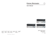
Rear Panel Features
Power and video input connections Output, user interface, and control connections
a AC power connector
h
RGB/HD BNC connectors
o
RJ-45 Ethernet connector
b
RGB/HD VGA connectors (inputs 1 and 2)
i
RGB/HD VGA connectors
p
9-pin RS-232 connectors
c
Universal BNC connectors (input 3)
j
(Optional) output card*
q
Reset button and LED
d
Component/S-video/composite BNC connectors (input 4)
k
MTP twisted pair connector
e
S-video/composite video BNC connectors (input 5)
l
PS/2 mouse port
f
DVI connector (input 6)
m
PS/2 keyboard port
g
(Optional) HD/SD-SDI connector (input 7)
n
USB A ports
*scan converter shown
50/60 Hz
100-240V 2A
RGB/R-Y, Y, B-Y
LAN
USB
RS-232
2
1
R-Y
R/
B-Y
B/
4
3
R/
R-Y
R/
R-Y
B-Y
/C
G/Y
VID
G/
Y
B/
B-Y
B/C
B-Y
H/HV
VID
/Y
V
VID
LO-
RES
OUT
R-Y
Y/
G
C
C
HDSDI/SDI
HV
S
I
N
P
U
T
S
O
U
T
P
U
T
S
RS-232
RESET
MOUSE
KEYBOARD
RGB/R-Y,Y,B-Y
VID
/Y
5
Y
MTP
DVI-D
7
6
7
1
2
5
3
4
6
15
16
10
9
13
11
14
8
RGB/R-Y,Y,B-Y
17
12
Mounting and Cabling
Step 1 — Mounting
Turn off or disconnect all equipment power sources and rack mount the Annotator
using the supplied brackets (see image at right).
Step 2 — Connect inputs
Connect inputs from video sources to the applicable connectors marked “Inputs”.
See b through g above for connector types and the image below for signal format.
RGBHV
H/
HV
R
/R-Y
V
G
/Y
B
/B-Y
R
/R-Y
V
G
/Y
RGBS/ RGBcvS video
H/
HV
B
/B-Y
R-Y
VID
/Y
B-Y
/C
RGsB/Component Video
(Y, R-Y, B-Y)
C
S-video
VID
/Y
Composite
video
VID
/Y
C
Step 3 — Connect outputs
Connect video output devices to the applicable connectors marked “Outputs” (see h through k above).
CAUTION Do not connect the MTP cable to the LAN port, or connect the LAN cable to the MTP port.
Step 4 — Connect user interface devices
PS/2 mouse and keyboard ports — Connect a mouse and/or a keyboard for annotation use.
Step 5 — Connect touch panel devices — USB or RS-232 connection
USB A ports — Connect a touch panel device to the Annotator via either of the USB A ports.
RS-232 — Using a NULL RS-232 cable only, connect a touch panel device to the Annotator via either of the RS-232 comm ports.
NOTE: USB and RS-232 driver configuration is necessary and must be done using the Signal Processing Products Control
Program (SPPCP). Within the SPPCP program click Help > Contents for configuration instructions.
See the Annotator User Guide, for Simple Instruction Set (SIS
™
) command definitions, and SPPCP use.

Annotator • Setup Guide (Continued)
2
Step 6 — Connect control devices
LAN Ethernet port — Connect an Ethernet LAN or WAN via this RJ-45 connector
o
for remote control of the Annotator using a
PC’s Internet browser, or the SPPCP control program.
One Ethernet connection LED lights green when connected to the LAN and one flickers amber as the devices communicate.
RS-232 ports — For serial RS-232 or RS-422 control, connect a host computer or control system via a 9-pin D connector
p
.
RS-232 protocol (default values): 9600 baud, 1 stop bit, no parity, 8 data bits, no flow control.
Step 7 — Connect power
AC power connector — Plug in a standard IEC power cord from a 100 to 240 VAC, 50 - 60 Hz power source into this receptacle
a
.
Powering Up
When powering up the Annotator, the unit undergoes a self testing sequence (see image below). The LCD displays the default
display cycle, showing the output rate and the refresh rates for the currently selected input.
When not in any menu mode the screen cycles through the input/output configuration currently installed.
3
sec.
10
sec.
Apply
Power
Extron
Annotator v1.xx
1
sec.
2 sec.
2
sec.
Default Display Cycle
Input #2
60.0kHz 75.0Hz
1024x768 60.0Hz
Output Rate
N The input and output rates shown in the default display
cycle may differ, depending on the type of video signal active.
Menu and Next buttons
remain lit.
All buttons flash in sequence
(green, red, amber).
MENU
NEXT
1
sec.
All input buttons
flash consecutively (amber).
2
1
1
sec.
2
1
Last active input
button remains lit.
= unlit
= lit
= flashing
Key
3
sec.
Loading OSD file
complete
Sorting graphics
files
Boot-up sequence
complete
Extron
Annotator v1.xx
3
sec.
Front Panel Overview
ANNOTATOR
ANNOTATION GRAPHICS PROCESSOR
ADJUST
DETAIL
ZOOM
/PAN
BRIGHT
/CONT
COLOR
/TINT
SIZE
POSITION
UNDO
/CLEAR
CAPTURE
/RECALL
AUTO
IMAGE
FREEZE
6 754321
MENU
NEXT
INPUTS
1
2
5
3
4
6 7
a Front panel configuration port — Connect a control system or computer to this (RS-232) port, using a TRS RS-232 cable,
Extron part number 70-335-01. RS-232 protocol (default values): 9600 baud, 1 stop bit, no parity, 8 data bits, no flow control
b Input selection buttons — Selects/switches inputs, and indicates which input is active (button lights amber).
c Special function buttons — These four, dual colored buttons are:
•Undo/Clear— Allows a reversal of up to the last seven annotation points. Press and hold to clear annotations.
•AutoImage— Allows automatic image adjustment on selected input.
•Capture/Recall— Allows the capture and saving of the current image or the recall of a saved image.
•Freeze— Allows the current displayed image to be frozen or unfrozen as desired.
d Picture contol buttons — These six, dual colored buttons are:
•Size—Allowsadjustmenttothedisplayedimagesize.
•Bright/Cont—Allowsadjustmentofthebrightnessandcontrastsettingsforthedisplayedimage.
•Detail—Allowsadjustmentofthedetail(sharpness)settingforthedisplayedimage.
•Position—Allowshorizontaland/orverticalpositionadjustmentofthedisplayedimage.
•Color/Tint—Allowsadjustmentofthecolorandtintsettingsforthedisplayedimage.
•Zoom/Pan—Allowsdisplayedimagetobezoomedinorbackout,orpannedhorizontallyand/orvertically.
e LCD display — This 16x2 screen displays device settings and menu configuration information.
f Menu navigation buttons (Menu, Next) — These buttons allow navigation through the Annotator's menu system.
g Adjust knobs — These are used with the picture adjustment and the menu navigation buttons to adjust settings.
Setting the Front Panel Locks (Executive Modes)
The Annotator has three modes of front panel security lock that limit the operation of the unit from the front panel.
Executive mode 0 (disabled) — The front panel is fully unlocked. This is the default setting.
Executive mode 1 (enabled) — The front panel is locked except for input switching, video freeze, and auto image.
Executive mode 2 (enabled) — The front panel is completely locked and can only be enabled and disabled using SIS commands.
See the online Annotator User Guide for SIS commands.

3
Sequence of crosses for
setting touch accuracy
Enabling or disabling Executive mode 1 from the front panel
To enable Executive mode 1 or 0, press and hold the Size and Position buttons simultaneously for 2 seconds. The display indicates
that Executive mode is either enabled or disabled. When the Annotator is in Executive mode 0 (unlocked), this selects mode 1
(locked) and if in Executive mode 1, this selects mode 0 (unlocked).
When either Executive mode (1 or 2) is enabled and a front panel action is attempted (other than input switching, video freeze,
and auto image), the LCD displays the status for 2 seconds. Executive mode 2 can only be enabled or disabled by SIS commands.
1
4
3
2
Conguring the Annotator
The Annotator has six front panel configuration menus with another menu available where optional boards are installed.
To use any menu, press the Menu button to access the Main menu, then repeatedly press the Menu button to cycle through the list
to the desired menu. Press Next to enter the desired submenu, and follow the steps below.
User
Presets
Menu
Output
Configuration
Exit Menu
Press NEXT
View Comm
Settings
Advanced
Configuration
Input
Configuration
Menu
Menu
Menu
Menu
NOTE: Press Menu at any time to exit a submenu and return to the main menu.
For detailed information on the menus, see the Annotator User Guide, available online at www.extron.com.
Configure the outputs, then the inputs, as follows:
1. Within the Output Configuration menu, use either Adjust knob to configure the output rate and resolution, the output signal
type, and the sync polarity.
2. From the Advanced Configuration menu, Test Pattern submenu, select the Alternating Pixels (Alt. Pixels) test pattern. Adjust
your display's active pixels, total pixels (clock), and pixel phase settings for optimal picture quality.
3. From the Advanced Configuration menu, change the test pattern to Crop, and adjust your display settings until all four sides
of the crop pattern are visible.
4. Use the Advanced Configuration menu to set the Aspect ratio (Fill or Follow). Rotate either Adjust knob to the desired setting.
5. Within the Input Configuration menu, press the applicable input button, then press Next to cycle to the desired submenu.
Rotate the right Adjust knob ({) to change the input values (for example, Input type, Film detection and so on) as required.
Use this menu to make any desired advanced adjustments including Horizontal and Vertical Start, Pixel Phase, Total Pixels,
Active Pixels, and Active Lines;
6. or Perform Auto-Image
™
. Auto-Image is a quick way to size an input to fit the current output window. To perform Auto-Image
on an input, press the Auto Image button. Press it again to confirm.
7. Use the Advanced Configuration menu to change image transition effect and RGB delay. Rotate either Adjust knob to select.
Touch Panel Conguration
If a USB or RS-232 touch panel screen is part of the system, a supporting module must be uploaded to the Annotator using SPPCP.
1. Connect to the Annotator via telnet using the SPPCP program.
2. Under the Tools menu, open the Device Module Configuration tool.
3. Select USB or RS-232 as applicable, and find the touch panel device in the list of available modules.
4. Select Add Module, and close the Tools menu when the upload is complete.
If your model is not listed, contact your Extron representative.
Touch Panel Calibration
If a touch panel screen is attached to the Annotator, the touch accuracy can be calibrated
using the Calibrate Panels setting in the Advanced configuration menu.
1. Within the Advanced configuration menu press Next to cycle to Calibrate Panels.
2. Press size and observe the touch panel screen. A cross appears in the upper left corner.
3. Tap the screen at the cross, which then moves to the top right corner.
4. Repeat by tapping the cross as it reappears in each corner, in sequence (see image at right).
5. After tapping the fourth cross, the unit saves the calibration data and restarts the sequence.
6. Repeat for each connected touch screen. Press any front panel button to exit the sequence and save the data.
Annotation Graphics Overview
The Annotator output can include a graphical toolbar, which is used for annotation. The toolbar slides in from the right side, and
can be accessed through a touch screen, or by using a compatible 2-button mouse attached to the rear PS/2 or USB port.
To open the tool bar, click on the green arrow at top right of the screen. The menu bar slides into view and, when enabled, the
toolbar stays visible down the right side of the display and allows for selection of various tools and controls. See page 4 for details.
To close the toolbar, click on the arrow again.
NOTE: By default, the tool bar closes after 10 seconds of inactivity. This duration can be modified using SIS commands.

4
Annotator • Setup Guide (Continued)
68-1661-50
Rev. D
04 12
Input Selection — This opens a pop-up palette displaying the
Annotator's selectable inputs. Selecting an input button
switches the display to that input.
Pointer — This changes the cursor to an extra large arrow of the
currently selected color.
Auto Image — When selected, the unit performs an Auto-Image
on the currently selected input.
Freehand — This allows freehand drawing on the display.
Line — This creates a straight line between two points.
Arrow — This creates a straight line with arrowheads.
Rectangle — This creates a rectangle with edges parallel to the
raster.
Ellipse — This creates an ellipse between the primary and the
opposite corner.
Text — This creates on-screen text at any point selected. Press
the Enter key to commit the text to the screen.
Highlighter — This creates a semi-transparent line allowing the
video to show through.
Size Select — This adjusts size of the annotation tool, such as
text size, after selecting the Text tool.
Eraser — This erases any (unsaved) annotations on the screen.
The size is defined by the line and size tool
Color — This allows up to 16 colors to be selected for any
drawing function (fill or outline), text, or pointer.
Fill — Select this in conjunction with selecting
rectangle or ellipse, to draw a solid shape, filled with
the currently selected color.
Undo — This reverses the last 7 completed
annotations or one Clear action.
Redo — If selected while using the Undo function, it
recreates the last undone annotation.
Clear — This clears the screen of all unsaved
annotations. Undo this with the Undo function.
Tools — This opens a secondary palette containing
the advanced tools: Capture, Freeze, Mute,
Whiteboard, Spotlight, Zoom, and Pan.
Capture — This takes a snapshot image of the current
program output, including annotations. Captured
images can be saved to the unit or a PC.
Freeze — This freezes the live video. Re-select to
unfreeze the video, or alternatively, switch inputs.
Mute — This mutes the video input and displays a
black screen. Annotations and menus are still visible.
Re-select to unmute, or alternatively, switch inputs.
Whiteboard — This creates a white screen for
annotations. Re-select to disable the whiteboard.
Spotlight — This creates a no-fill ellipse to focus on
a specific area of the screen, while the outer area
brightness is greatly reduced.
Zoom — This zooms in on a specific area of the screen.
Using the cursor, create a rectangle at that area.
Pan — Select this while an image is zoomed in, to
move the focus to a new area. Place the cursor on a
zoomed image and drag to the new area.
Basic SIS Commands Table
The Annotator can be configured with specific SIS commands via RS-232 or a LAN connection. This table lists a selection of the
commands. For a full list of SIS commands refer to the Annotator User Guide, online at www.extron.com.
Command ASCII command
(host to switcher)
Response
(switcher to host)
Additional description
Select input
X!
!
In
X!]
Select video from input
X!
.
Execute Auto-Image
A Img
]
Execute auto image for current input.
Mute video to black
1B
Vmt1
]
Mute video and display a black screen.
Mute video to white
2B
Vmt2
]
Mute video and display a white screen.
Unmute video
0B
Vmt0
]
Unmute video mute.
Freeze input
1F
Frz1
]
Freeze
s
elected input.
Unfreeze input
0F
Frz0
]
Unfreeze
s
elected input.
Show/hide annotations
EX@Ashw} Ashw X@]
Set output(s) to display annotations.
Show/hide cursor
EX@Cshw} Cshw X@]
Set output(s) to display cursor.
Show/hide OSD menu
EX@Mshw} Mshw X@]
Set output(s) to display OSD menu.
Clear all annotations
E0Edit}
Edit0
]
Clears all annotations on the output (can be undone).
NOTE:
X!
= Input number (1 – 7)
X@
= Output selections: 0 = All (default), 1 = Group 1 only (BNC, MTP, optional output card), 2 = Group 2 only (VGA), 3 = None
Extron Headquarters
+1.800.633.9876 (Inside USA/Canada Only)
Extron Asia
+65.6383.4400
Extron China
+86.21.3760.1568)
Extron Korea
+82.2.3444.1571
Extron Europe
+31.33.453.4040
Extron Japan
+81.3.3511.7655
Extron Middle East
+971.4.2991800
Extron India
+91.80.3055.3777
© 2012 Extron Electronics — All rights reserved. All trademarks mentioned are the property of their respective owners. www.extron.com
Annotation Graphics — Button Selection
/