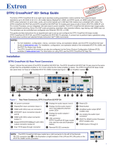
Power and video input connections Outputs and control connections
A AC power connector
B Universal analog 15-pin HD connector
C HDMI connector (HDMI/DVI inputs)
D DisplayPort connector
E HDMI connectors (2) (HDMI/DVI outputs)
F
RJ-45 connector (DTP or HDBaseT
output), selectable by DIP switch
G
5-pole captive screw connector
(for DTP RS-232 and IR insert)
H
USB A connectors (2)
I
Reset button and LED
J
RJ-45 LAN connector
K
Remote RS-232 3-pole captive
screw connector
L
Remote contact closure 3-pole
captive screw connector
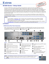
Input Selection — This opens a pop-up palette
displaying the selectable inputs. Selecting an input
button switches the display to that input.
Fill — Select this when selecting rectangle or ellipse,
to draw a solid shape filled with the selected color.
Pointer — This changes the cursor to an extra large
arrow of the currently selected color.
Undo — This undoes the last 15 completed annotations or
a Clear action.
Auto Image — When selected, the unit performs an
Auto-Image on the currently selected input.
Redo — If selected while using the Undo function, it
recreates the last undone annotation.
Freehand — This allows freehand drawing on the
display.
Clear — This clears the screen of all unsaved annotations.
This action can be undone with the Undo function.
Line — This creates a straight line between two points.
Tools — This opens a secondary palette with advanced
tools: Capture, Freeze, Mute, Whiteboard, Spotlight, Zoom,
and Pan.
Arrow — This creates a straight line with an arrowhead.
Capture — This takes a snapshot image of the current
program output, including annotations. Captured images
can be saved to the unit or PC.
Rectangle — This creates a rectangle with edges
parallel to the raster.
Freeze — This freezes the live video. Re-select to unfreeze
the video, or alternatively, switch inputs.
Ellipse — This creates an ellipse between the primary
and the opposite corner.
Mute — This mutes the video input and displays a black
screen. Annotations and menus are still visible. Re-select
to unmute.
Text — This creates on-screen text at any point
selected. Press the <Enter> key to commit the text to
the screen.
Whiteboard — This creates a white screen for annotations.
Re-select to disable the whiteboard.
Highlighter — This creates a semi-transparent line
allowing the video to show through.
Spotlight — This creates a no-fill ellipse to focus on a
specific area of the screen, while the brightness of the
outer area is greatly reduced.
Size Select — This adjusts size of the annotation tool,
such as text size, after selecting the Text tool.
Zoom — This zooms in on a specific area of the screen.
Using the cursor, create a rectangle at that area. Create a
rectangle of less than 100 pixels to reset zoom to default.
Eraser — This erases any (unsaved) annotations on the
screen. The size is defined by the size tool.
Pan — Select this while an image is zoomed in, to
move the focus to a new area. Place the cursor on a
zoomed image and drag to the new area.
Color — This allows up to 16 colors to be selected for
any drawing function (fill or outline), text, or pointer.
Basic SIS Commands Table
The Annotator 300 can be congured with specic SIS commands via USB, RS-232, or a LAN connection. This table lists a selection of
the commands. For a full list of SIS commands see the Annotator 300 User Guide, online at www.extron.com.
Command ASCII command
(host to annotator)
Response
(annotator to host)
Additional description
Select input
X!! InX!
]
Select video from input
X!
.
Execute Auto-Image
A Img0
]
Execute an Auto-Image.
Mute video to black
X#*1B
Vmt
X#*
1
]
Mute
X#
video and display to a black screen.
Unmute video
X#*0B
Vmt
X#*
0
]
Unmute video mute.
Freeze input
1F
Frz1
]
Freeze
selected input.
Unfreeze input
0F
Frz
0]
Unfreeze selected input.
Show/hide annotations
EX#Ashw} Ashw X#]
Set output(s) to display the annotations.
Show/hide cursor
EX#Cshw} Cshw X#]
Set output(s) to display the cursor.
Show/hide OSD menu
EX#Mshw} Mshw X#]
Set output(s) to display the OSD menu.
Clear all annotations
E0Edit}
Edit
0]
Clears all annotations on the output (can be undone).
NOTE:
X!
= Input number: 1, 2, or 3
X#
= Output group selections: 0 = All (default), 1 = Output 1 only (HDMI), 2 = Output 2A and 2B only (HDMI and DTP), 3 = None
Extron USA Headquarters
+1.800.633.9876 (Inside USA/Canada Only)
Extron USA - West: +1.714.491.1500 FAX: +1.714.491.1517
Extron USA - East: +1.919.850.1000 FAX: +1.919.850.1001
© 2014 Extron Electronics — All rights reserved. All trademarks mentioned are the property of their respective owners. www.extron.com
Annotator 300 • Setup Guide (Continued)
68-2378-50
Rev. A
04 14
4