Page is loading ...

User Guide
Annotator 300
Signal Processors
HDCP-Compliant Annotation Graphics Processor
68-2378-01 Rev. A
08 14

i
Precautions
Safety Instructions
Safety Instructions • English
WARNING: This symbol, , when used on the product, is intended to
alert the user of the presence of uninsulated dangerous voltage within the
product’s enclosure that may present a risk of electric shock.
ATTENTION: This symbol, , when used on the product, is intended
to alert the user of important operating and maintenance (servicing)
instructions in the literature provided with the equipment.
For information on safety guidelines, regulatory compliances, EMI/EMF
compatibility, accessibility, and related topics, see the Extron Safety and
Regulatory Compliance Guide, part number 68-290-01, on the Extron website,
www.extron.com.
Instructions de sécurité • Français
AVERTISSEMENT : Ce pictogramme, , lorsqu’il est utilisé sur le
produit, signale à l’utilisateur la présence à l’intérieur du boîtier du produit
d’une tension électrique dangereuse susceptible de provoquer un choc
électrique.
ATTENTION : Ce pictogramme, , lorsqu’il est utilisé sur le produit,
signale à l’utilisateur des instructions d’utilisation ou de maintenance
importantes qui se trouvent dans la documentation fournie avec le
matériel.
Pour en savoir plus sur les règles de sécurité, la conformité à la réglementation,
la compatibilité EMI/EMF, l’accessibilité, et autres sujets connexes, lisez les
informations de sécurité et de conformité Extron, réf. 68-290-01, sur le site
Extron, www.extron.com.
Sicherheitsanweisungen • Deutsch
WARNUNG: Dieses Symbol auf dem Produkt soll den Benutzer
darauf aufmerksam machen, dass im Inneren des Gehäuses dieses
Produktes gefährliche Spannungen herrschen, die nicht isoliert sind
und die einen elektrischen Schlag verursachen können.
VORSICHT: Dieses Symbol auf dem Produkt soll dem Benutzer in der
im Lieferumfang enthaltenen Dokumentation besonders wichtige Hinweise
zur Bedienung und Wartung (Instandhaltung) geben.
Weitere Informationen über die Sicherheitsrichtlinien, Produkthandhabung,
EMI/EMF-Kompatibilität, Zugänglichkeit und verwandte Themen finden Sie in
den Extron-Richtlinien für Sicherheit und Handhabung (Artikelnummer
68-290-01) auf der Extron-Website, www.extron.com.
Instrucciones de seguridad • Español
ADVERTENCIA: Este símbolo, , cuando se utiliza en el producto,
avisa al usuario de la presencia de voltaje peligroso sin aislar dentro del
producto, lo que puede representar un riesgo de descarga eléctrica.
ATENCIÓN: Este símbolo, , cuando se utiliza en el producto, avisa
al usuario de la presencia de importantes instrucciones de uso y
mantenimiento recogidas en la documentación proporcionada con el
equipo.
Para obtener información sobre directrices de seguridad, cumplimiento
de normativas, compatibilidad electromagnética, accesibilidad y temas
relacionados, consulte la Guía de cumplimiento de normativas y seguridad de
Extron, referencia 68-290-01, en el sitio Web de Extron, www.extron.com.
Инструкция по технике безопасности • Русский
ПРЕДУПРЕЖДЕНИЕ: Данный символ, , если указан
на продукте, предупреждает пользователя о наличии
неизолированного опасного напряжения внутри корпуса
продукта, которое может привести к поражению
электрическим током.
ВНИМАНИЕ: Данный символ, , если указан на продукте,
предупреждает пользователя о наличии важных инструкций
по эксплуатации и обслуживанию в руководстве,
прилагаемом к данному оборудованию.
Для получения информации о правилах техники безопасности,
соблюдении нормативных требований, электромагнитной
совместимости (ЭМП/ЭДС), возможности доступа и других
вопросах см. руководство по безопасности и соблюдению
нормативных требований Extron на сайте Extron: www.extron.com,
номер по каталогу - 68-290-01.
Chinese Simplified(简体中文)
警告: 产品上的这个标志意在警告用户该产品机壳内有暴露的危险 电压,
有触电危险。
注意: 产品上的这个标志意在提示用户设备随附的用户手册中有
重要的操作和维护(维修)说明。
关于我们产品的安全指南、遵循的规范、EMI/EMF 的兼容性、无障碍
使用的特性等相关内容,敬请访问 Extron 网站 www.extron.com,参见
Extron 安全规范指南,产品编号 68-290-01。
Chinese Traditional( )
警告: 若產品上使用此符號,是為了提醒使用者,產品機殼內存在著
可能會導致觸電之風險的未絕緣危險電壓。
注意 若產品上使用此符號,是為了提醒使用者,設備隨附的用戶手冊中有重
要 的 操 作 和 維 護( 維 修 )説 明。
有關安全性指導方針、法規遵守、EMI/EMF 相容性、存取範圍和相關主題的詳細資
訊,請瀏覽 Extron 網站:www.extron.com,然後參閱《Extron 安全性與法規
遵守手冊》,準則編號 68-290-01。
Japanese
警告: この記号 が製品上に表示されている場合は、筐体内に絶縁されて
いない高電圧が流れ、感電の危険があることを示しています。
注意: この記号 が製品上に表示されている場合は、本機の取扱説明書
に 記 載 されている重要な操 作と保 守(整 備)の指 示についてユーザー の 注
意を喚起するものです。
安全上のご注意、法規厳守、EMI/EMF適合性、その他の関連項目に
つ い て は 、エ ク スト ロ ン の ウェブ サ イト www.extron.com よ り 『 Extron Safety
and Regulatory Compliance Guide』 ( P/N 68-290-01) をご覧ください。
Korean
경고: 이 기호 가 제품에 사용될 경우, 제품의 인클로저 내에 있는
접지되지 않은 위험한 전류로 인해 사용자가 감전될 위험이 있음을
경고합니다.
주의: 이 기호 가 제품에 사용될 경우, 장비와 함께 제공된 책자에 나와
있는 주요 운영 및 유지보수(정비) 지침을 경고합니다.
안전 가이드라인, 규제 준수, EMI/EMF 호환성, 접근성, 그리고 관련 항목에
대한 자세한 내용은 Extron 웹 사이트(www.extron.com)의 Extron 안전 및
규제 준수 안내서, 68-290-01 조항을 참조하십시오.

ii
FCC Class A Notice
This equipment has been tested and found to comply with the limits for a Class A digital device,
pursuant to part15 of the FCC rules. The ClassA limits provide reasonable protection against harmful
interference when the equipment is operated in a commercial environment. This equipment generates,
uses, and can radiate radio frequency energy and, if not installed and used in accordance with the
instruction manual, may cause harmful interference to radio communications. Operation of this
equipment in a residential area is likely to cause interference. This interference must be corrected at
the expense of the user.
NOTE: For more information on safety guidelines, regulatory compliances, EMI/EMF compatibility,
accessibility, and related topics, see the “Extron Safety and Regulatory Compliance
Guide” on the Extron website.
Copyright
© 2014 Extron Electronics. All rights reserved.
Trademarks
All trademarks mentioned in this guide are the properties of their respective owners.
The following registered trademarks
®
, registered service marks
(SM)
, and trademarks
(TM)
are the property of
RGBSystems, Inc. or Extron Electronics:
Registered Trademarks
(®)
AVTrac, Cable Cubby, CrossPoint, eBUS, EDID Manager, EDID Minder, Extron, Flat Field, GlobalViewer, Hideaway, Inline, IPIntercom,
IPLink, Key Minder, LockIt, MediaLink, PlenumVault, PoleVault, PowerCage, PURE3, Quantum, SoundField, SpeedMount, SpeedSwitch,
SystemINTEGRATOR, TeamWork, TouchLink, V-Lock, VersaTools, VN-Matrix, VoiceLift, WallVault, WindoWall, XTP, and XTPSystems
Registered Service Mark
(SM)
: S3 Service Support Solutions
Trademarks
(
™
)
AAP, AFL (Accu-Rate Frame Lock), ADSP (Advanced Digital Sync Processing), Auto-Image, CableCover, CDRS (Class D Ripple Suppression),
DDSP (Digital Display Sync Processing), DMI (Dynamic Motion Interpolation), DriverConfigurator, DSPConfigurator, DSVP (Digital Sync
Validation Processing), EQIP, FastBite, FOXBOX, Global Configurator, IP Intercom HelpDesk, Link License, MAAP, MicroDigital, ProDSP, QS-
FPC (QuickSwitch Front Panel Controller), Scope-Trigger, SIS, Simple Instruction Set, Skew-Free, SpeedNav, Triple-Action Switching, XTRA,
ZipCaddy, ZipClip

iii
Conventions Used in this Guide
Notifications
The following notifications are used in this guide:
CAUTION: Risk of minor personal injury.
ATTENTION : Risque de blessuremineure.
ATTENTION :
• Risk of property damage.
• Risque de dommages matériels.
NOTE: A note draws attention to important information.
Software Commands
Commands are written in the fonts shown here:
^AR Merge Scene,,Op1 scene 1,1 ^B 51 ^W^C
[01] R 0004 00300 00400 00800 00600 [02] 35 [17] [03]
E X! *X1&* X2)* X2#* X2! CE}
NOTE: For commands and examples of computer or device responses mentioned
in this guide, the character “0” is used for the number zero and “O” is the capital
letter “o.”
Computer responses and directory paths that do not have variables are written in the font
shown here:
Reply from 208.132.180.48: bytes=32 times=2ms TTL=32
C:\Program Files\Extron
Variables are written in slanted form as shown here:
ping xxx.xxx.xxx.xxx —t
SOH R Data STX Command ETB ETX
Selectable items, such as menu names, menu options, buttons, tabs, and field names are
written in the font shown here:
From the File menu, select New.
Click the OK button.
Specifications Availability
Product specifications are available on the Extron website, www.extron.com.

Contents
Introduction ....................................................1
About this User Guide ..................................... 1
About the Annotator 300 ................................. 1
Features .......................................................... 2
Installation ...................................................... 6
UL/Safety Requirements .................................. 6
Important Safety Instructions ....................... 6
Mounting the Annotator 300 ............................ 7
Tabletop Placement ..................................... 7
UL Guidelines for Rack Mounted Devices ... 7
Rack Mounting ............................................ 7
Rear Panel Features and Connections ........8
Rear Panel Features ........................................ 8
Power and Video Input Connections ............ 8
Output, User Interface, and Control
Connections ............................................... 9
Installation and Cabling .............................. 10
Powering Up ............................................. 11
Resetting the Unit with the Reset Button ....... 12
Operation ..................................................... 14
Front Panel Overview ..................................... 14
The Annotator 300 Menu System .................. 15
Overview of Menus .................................... 15
Using the Menus........................................ 17
User Presets .............................................. 17
Input Configuration .................................... 18
Output Configuration ................................. 19
Advanced Configuration ............................ 20
View Comm Settings ................................. 21
Edit Comm Settings ................................... 21
Exit Menu .................................................. 21
Capture/Recall Settings
(front panel activated) ............................... 22
Setting the Front Panel Locks
(Executive Modes) ........................................ 24
Enabling or Disabling Executive Mode
2 from the Front Panel .............................. 24
On Screen Annotation ................................. 25
Touch Panel Configuration ............................. 25
USB Port Connections .................................. 26
Touchscreen Calibration ................................ 26
Annotation Overview ...................................... 27
Default Annotation Buttons ............................ 28
SIS Communication and Control ............... 31
Front Panel Configuration Port ....................... 31
Ethernet Connection ...................................... 31
Ethernet (LAN) Port .................................... 31
Ethernet Cabling ........................................ 31
Default IP Addresses ................................. 31
Establishing a Connection.......................... 32
Connection Time-outs ............................... 32
Number of Connections ............................. 32
Using Verbose Mode ................................. 32
Host-to-Processor Instructions ...................... 32
Processor-Initiated Messages ........................ 33
Processor Error Responses ....................... 33
Using the Command/Response Table
for SIS Commands ....................................... 34
Symbol Definitions ..................................... 34
Command/Response Table for
SIS Commands ........................................ 42
Using the Command/Response Table
for IP SIS Commands ................................... 57
Symbol Definitions ..................................... 57
Command/Response Table for
IP SIS Commands .................................... 60
Product
Configuration Software ............................... 63
Installing the Software .................................... 63
Starting the Software ..................................... 64
Device Discovery Panel .............................. 64
TCP/IP Panel ............................................. 65
Offline Device Preview ................................ 66
Using the Software ........................................ 67
Device Menu.............................................. 68
Software Menu .......................................... 72
AV Controls Panel .......................................... 74
Configuration Pages ...................................... 76
Annotator 300 • Contents iv

Input and Output Configuration Page ......... 76
EDID Minder Page ..................................... 79
Image Settings Page.................................. 81
Signal Sampling panel ............................... 81
Size and Position Page .............................. 84
Annotations Settings Page ......................... 85
OSD Settings Page .................................... 88
General Settings Page ............................... 90
Accessing the Web Page ............................... 92
Accessing the Default Web Page ................... 92
Navigating the Default Web Page .................. 93
Communication Settings ............................ 93
Input/Output Status ................................... 94
Date and Time ........................................... 95
Configure This Device ................................ 96
Device Info ................................................. 96
Passwords................................................. 97
Ethernet Connection ................................... 99
Ethernet Link ................................................. 99
Ethernet Connection .................................. 99
Default Address ......................................... 99
Telnet Tips ............................................... 101
Subnetting Basics .................................... 102
Warranty ..................................................... 106
Contact Information .................................. 106
Annotator 300 • Contents v

Introduction
This section describes this guide and features of the Annotator 300, including:
• About this User Guide
• About the Annotator 300
• Features
About this User Guide
This guide contains information to install, configure, and operate the Extron
Annotator 300 HDCP-Compliant Annotation Graphics Processor with DTP Extension.
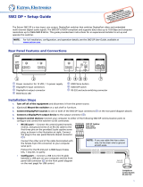
About the Annotator 300
The Extron Annotator 300 is a high performance, hardware-based annotation processor
that allows a presenter to draw, point, or type over live presentations using a touch display,
graphics tablet, or a keyboard and mouse.
The HDCP-compliant Annotator 300 includes HDMI and DisplayPort inputs, a universal
analog video input, and three simultaneous outputs including two HDMI and a DTP
twisted pair output. It also features advanced Extron video signal processing with a high
performance scaling engine and fast, reliable switching. The DTP twisted pair output
extends HDMI and bidirectional control signals to a DTP receiver over a shielded twisted
pair cable up to 330 feet (100 meters). The Annotator 300 offers a wide range of annotation
tools and controls, all easily accessible by the presenter using an intuitive on-screen GUI.
L
R
POWE
R
12V
0.7A MAX
A
UDIO
S
I
G
LI
NK
DTP IN
OUTPUTS
eBUS
FLEX
I/O
RELAYSIR/SERIAL
COM
12 VDC
LAN
+V
Tx Rx
G
Tx Rx G
Tx Rx
G
Tx Rx G S G
S G S G
S
G
RTSCTS
+ - + -
+
-
+
-
-S G
PWR O UT = 12
W
+S
S G
S G S G
S
G
Tx Rx
G
Tx Rx G
Tx Rx
G
Tx Rx G RTSCTS
1 2 3 4 G
1 2 3 4
5
6 7
8
1
1 2
3
4
5 6 7
8
2
3
7
4
5
6
8
1
2
3
100-240V ~ 50-60Hz
5A
MAX
SWITCHED 12 VDC
40W MAX
TOTAL
4
IPCP PRO 550
OVER
DTP
REMOTE
RS-232 IR
Tx R
x
G
T
x R
x
CONTACT
1
2 3
RS-232
Tx
Rx
G
LINK
SIG
DTP OU
T
DTP
HDBT
OUTPUTS
INPUTS
1 1UNIVERSAL HDMI DISPL
AYPORT2 3 HDMI 2A HDMI 2B
LA
N
RES
ET
USB
1
2
50/60
Hz
100-240VAC
--
A
M
AX
USB
CAPTURE
RECALL
MENU
NEXT
INPUTS
1
2
3
AUTO
IMAGE
ADJUST
CONFIG
Help
System
Off
Display
Room
Control
Off
Mute
Screen
Lighting
December 15, 2013 - 7:58 AM
Audio
Control
Volume
Mute
Tuner
1 2 3
VCR
Laptop
PC
DVD
Doc
Cam
Tuner
On
Channel
Last
Presets
More
Presets
3
2
1
6
5
4
9
8
7
Enter
0
Extron
Annotator 300
HDCP-Compliant
Annotation
Processor with
DTP Extension
Annotator 300
Front
Touchscreen 1
USB
USB
HDMI
VGA
HDMI
DisplayPort
HDMI
HDMI
Touchscreen 2
Projector
USB Flash
Drive
Laptop
MacBook
Extron
DTP HDMI 330 Rx
Receiver
CATx Cable
up to 330' (100 m)
Document
Camera
AV Control
Network
Ethernet
Ethernet
Ethernet
RS-232
RS-232
Extron
IPCP Pro 550
IP Link Pro
Control Processor
Extron
TLP Pro 1020T
10" Ta bletop TouchLink
Pro Touchpanel
Figure 1. Typical Annotator 300 Application
Annotator 300 • Introduction 1

Features
• Live annotation capabilities plus high performance scaling and switching —
The Annotator 300 allows a presenter to draw, point, or add text in real-time over live
video and graphics presentations.
• Inputs — Includes one HDMI; one DisplayPort; one universal 15-pin HD input for
RGB, component video, S-video, or composite video.
• Outputs — Includes two HDMI, one DTP twisted pair output on RJ-45
• Integrated three-input switcher with HDMI, DisplayPort, and universal analog
video inputs — The Annotator 300 delivers fast, reliable input switching between
HDMI, DisplayPort, and analog video sources. The universal auto-detecting analog
video input automatically detects incoming RGB, component video, S-video, or
composite video.
• Three simultaneous video outputs — One DTP twisted pair output and two HDMI
outputs are available for driving three displays.
• Integrated DTP output supports transmission of HDMI with embedded audio
and control up to 330 feet (100 meters) over a shielded STP cable — The DTP
output supports digital signal transmission of HDMI with embedded audio and control
up to 330 feet (100 meters) over a shielded STP cable, providing high reliability and
maximum performance on an easily installed cable infrastructure.
• Intuitive graphical annotation interface — A user-friendly on-screen display
enables quick and easy annotation. Essential annotation tools are available for
drawing freehand or lines, adding rectangular or elliptical shapes, typing text,
highlighting an area of an image, pointing to an object on-screen, and using the
screen as a whiteboard. Customization options are available for text and graphics,
including point size and color.
• Hardware-based graphics and video processing — The Annotator 300 features
a fully hardware-based system architecture designed to deliver the performance and
operational reliability essential for mission-critical applications.
• Compatible with popular touch displays and graphics tablets — The Annotator
300 supports a wide variety of touch displays and graphics tablets from third-party
manufacturers, and also can be used with a standard keyboard and mouse.
• Capture, store, and recall images — An image can be captured as a snapshot
of the live video output, including annotations, and saved to internal memory, a
removable USB flash drive, or a network location for archiving.
• Print captured images using a network printer — The Annotator 300 supports
connection to a printer on the network, enabling captured images to be sent directly
to the printer without connecting to a PC.
• Configurable Main and Confidence outputs — The outputs can be configured
as separate Main and Confidence outputs with individually controlled visibility of
annotation and OSD graphics.
• HDCP compliant — Fully supports HDCP-encrypted sources, with selectable
authorization for unencrypted content.
• Supported HDMI specification features include data rates up to 6.75 Gbps, Deep
Color, and HD lossless audio formats
• Supports DisplayPort input signals at resolutions up to 2560x1600
• Compatible with shielded twisted pair cable — The Annotator 300 fully supports
a maximum transmission distance of 330 feet (100 meters) for all compatible
resolutions when used with shielded twisted pair cable. Shielded twisted pair cabling
with solid center conductor sizes of 24 AWG or better is recommended for optimal
performance.
Annotator 300 • Introduction 2

• Extron XTP DTP 24 shielded twisted pair cable is strongly recommended for
optimal performance
• Bidirectional RS-232 and IR pass-through for AV device control — Bidirectional
RS-232 control and IR signals can be transmitted alongside the video signal over
the DTP connection, allowing the remote device to be controlled without the need
for additional cabling. Bidirectional control extension eliminates the need for control
system wiring to remote devices.
• Remote powering of DTP receiver — The Annotator 300 can provide remote
power to a DTP receiver over the twisted pair connection, eliminating the need for a
separate power supply at the remote unit.
• Compatible with all DTP 230 and DTP 330 Series receivers, and DTP-enabled
products — Enables mixing and matching with desktop and wallplate receivers, as
well as other DTP-enabled products to meet application requirements.
• DTP output is compatible with HDBaseT-enabled devices — The DTP output
can be configured to send video and embedded audio, plus bidirectional RS-232 and
IR signals to an HDBaseT-enabled display.
• Auto-switching between inputs — Auto-switching allows for simple, unmanaged
installation in locations such as in a lectern or under a conference table. When
multiple inputs are active, the switching priority is configurable.
• Auto Input Format Detection — For the universal analog video input, the Annotator
300 detects the incoming signal format, automatically reconfiguring itself to provide
the appropriate decoding and signal processing. This feature can reduce the number
of required outputs for a matrix switcher, lowering system cost while improving
manageability.
• Selectable output rates from 640x480 to 1920x1200, including HDTV 1080p/60
and 2K — Available output rates include computer-video up to 1920x1200, HDTV
rates up to 1080p/60, and 2K.
• Advanced scaling engine with 30-bit processing and 1080i deinterlacing —
Image scaling and video format conversion are performed at 30-bit precision for
enhanced color accuracy and picture detail. High performance deinterlacing of 1080i
signals from HD sources delivers optimized image quality.
• Key Minder continuously verifies HDCP compliance for quick, reliable
switching — Key Minder authenticates and maintains continuous HDCP encryption
between input and output devices to ensure quick and reliable switching in
professional AV environments, while enabling simultaneous distribution of a single
source signal to one or more displays.
• EDID Minder automatically manages EDID communication between
connected devices — EDID Minder ensures that all sources power up properly and
reliably output content for display.
• SpeedSwitch Technology provides exceptional switching speed for HDCP-
encrypted content
• Aspect ratio control — The aspect ratio of the video output can be controlled by
selecting a FILL mode, which provides a full screen output, or a FOLLOW mode,
which preserves the original aspect ratio of the input signal.
• HDCP authentication and signal presence confirmation — Provides real-time
verification of HDCP status for each digital video input and output. This allows for
easy signal and HDCP verification through RS-232 or Ethernet, providing valuable
feedback to a system operator or helpdesk support staff.
Annotator 300 • Introduction 3

• HDCP Visual Confirmation provides a green signal when encrypted content
is sent to a non-compliant display — A full-screen green signal is sent when
HDCP-encrypted content is transmitted to a non-HDCP compliant display, providing
immediate visual confirmation that protected content cannot be viewed on the display.
• HDMI to DVI Interface Format Correction — Automatically enables or disables
embedded audio and InfoFrames, and sets the correct color space for proper
connection to HDMI and DVI displays.
• Seamless switching — Seamless cut through black and fade through black
transition effects are available to enhance presentations by eliminating distractions
during switching.
• Auto-Image setup — When activated, the unit automatically optimizes the image
by analyzing and adjusting to the video input signal. This can save time and effort in
setting up a newly connected source, particularly in presentation environments where
different guest presenter laptops with various output resolutions will be connected.
• Auto Input Memory — When activated, the unit automatically stores size, position,
and picture settings based on the incoming signal. When the same signal is detected
again, these image settings are automatically recalled from memory.
• Output Standby Mode — The unit can be set to automatically mute video and sync
output to the display device when no active input signal is detected. This allows the
projector or flat-panel display to automatically enter into standby mode to save energy
and enhance lamp or panel life.
• Power Save Mode — The unit can be placed in a low power standby state to
conserve energy when not in use.
• AFL - Accu-RATE Frame Lock — A patented technology exclusive to Extron that
locks the output frame rate to a designated input to eliminate stuttering caused by
frame rate conversion.
• Image freeze control — A live image can be frozen using RS-232 serial control,
USB, Ethernet control, or the annotation GUI.
• Picture controls — Available for adjusting brightness, contrast, color, tint, and detail,
as well as horizontal and vertical positioning and sizing.
• Quad standard video decoding — A temporal, 3D adaptive comb filter provides
advanced decoding of composite NTSC 3.58, NTSC 4.43, PAL, and SECAM for
integration into systems worldwide.
• User presets — Memory presets are available for each input to store and recall
optimized image settings.
• Automatic 3:2 and 2:2 pulldown detection — Advanced film mode processing
techniques that help maximize image detail and sharpness for NTSC, PAL, and
HDTV 1080i sources that originated from film.
• Internal video test patterns for calibration and setup — The unit offers several
video test patterns to facilitate proper system setup and calibration of display devices.
• Integrated audio delay — Embedded audio is passed through to all outputs and
automatically delayed to compensate for latency introduced by the video processing.
• Front panel security lockout — This feature locks out all front panel functions
except for input selection; all functions however, are available through Ethernet, USB,
or RS-232 control.
• Ethernet monitoring and control — Enables control and proactive monitoring over
a LAN, WAN, or the Internet.
• Built-in Web pages — Enables the use of a standard browser for monitoring over an
intuitive Web interface.
Annotator 300 • Introduction 4

• RS-232 control port — Enables the use of serial commands for complete control
and configuration via the Extron Windows®-based control program, or integrated into
a control system. Extron products use the SIS™ - Simple Instruction Set command
protocol, a set of basic ASCII commands that allow for quick and easy programming.
• Front panel USB configuration port — Enables easy configuration without having
to access the rear panel.
• Contact closure ports — Can be used for external control of source switching.
• RJ-45 signal and link LED indicators for DTP port — Provides a means for
validating signal flow and operation, allowing quick identification of connectivity
issues.
• Easy setup and commissioning with the Extron Product Configuration
Software (PCS) — Conveniently configure multiple products using a single software
application.
• Rack-mountable 1U, full rack width metal enclosure
• Includes LockIt HDMI cable lacing brackets
• Highly reliable, energy-efficient internal universal power supply — The
100-240 VAC, 50/60 Hz, international power supply provides worldwide power
compatibility with high demonstrated reliability.
Annotator 300 • Introduction 5

Installation
This section contains installation information for the Extron Annotator 300. It covers the
following subjects:
• UL/Safety Requirements
• Mounting the Annotator 300
UL/Safety Requirements
The Underwriters Laboratories (UL) requirements listed below pertain to the safe
installation and operation of this Annotation Graphics Processor.
Important Safety Instructions
1. Read these instructions.
2. Keep these instructions.
3. Heed all warnings.
4. Follow all instructions.
5. Do not use this apparatus near water.
6. Clean only with a dry cloth.
7. Do not block any ventilation openings. Install in accordance with the manufacturer’s
instructions.
8. Do not install near any heat sources such as radiators, heat registers, stoves, or other
apparatus (including amplifiers) that produce heat.
9. Do not defeat the safety purpose of the polarized or grounding type plug. A polarized
plug has two blades with one wider than the other. A grounding type plug has two
blades and a third grounding prong. The wide blade or the third prong are provided
for your safety. If the provided plug does not fit into your outlet, consult an electrician
for replacement of the obsolete outlet.
10. Protect the power cord from being walked on or pinched particularly at plugs,
convenience receptacles, and the point where they exit from the apparatus.
11. Only use attachments/accessories specified by the manufacturer.
12. Use only with the cart, stand, tripod, bracket, or table specified by the manufacturer,
or sold with the apparatus. When a cart is used, use caution when moving the cart/
apparatus combination to avoid injury from tip-over.
13. Unplug this apparatus during lightning storms or when unused for long periods of
time.
14. Refer all servicing to qualified service personnel. Servicing is required when the
apparatus has been damaged in any way, such as power-supply cord or plug is
damaged, liquid has been spilled or objects have fallen into the apparatus, the
apparatus has been exposed to rain or moisture, does not operate normally, or has
been dropped.
Annotator 300 • Installation 6

Mounting the Annotator 300
If the Annotator 300 is to be rack mounted, it is important to mount it before cabling it.
Four rubber feet are included with the unit. Install the feet only if the unit is to be mounted
on a table top (see “Tabletop Placement” below).
Tabletop Placement
For tabletop placement, install the self-adhesive rubber feet/pads (provided) onto the four
corners of the bottom of the device.
UL Guidelines for Rack Mounted Devices
The following Underwriters Laboratories (UL) guidelines pertain to the safe installation of
the Annotator 300 in a rack.
1. Elevated operating ambient temperature — If installed in a closed or multi-unit rack
assembly, the operating ambient temperature of the rack environment may be greater
than room ambient temperature. Therefore, install the device in an environment
compatible with the maximum ambient temperature (Tma = +122 °F, +50 °C) as
specified by Extron.
2. Reduced air flow — Install the equipment in a rack so that the amount of air flow
required for safe operation of the equipment is not compromised.
3. Mechanical loading — Mount the equipment in the rack so that a hazardous condition
is not achieved due to uneven mechanical loading.
4. Circuit overloading — Connect the equipment to the supply circuit and consider the
effect that circuit overloading might have on overcurrent protection and supply wiring.
Appropriate consideration of equipment nameplate ratings should be used when
addressing this concern.
5. Reliable earthing (grounding) — Maintain reliable grounding of rack-mounted
equipment. Pay particular attention to supply connections other than direct
connections to the branch circuit (for example, use of power strips).
Rack Mounting
Mount the Annotator 300 to a rack using the pre-installed rack ears (see figure 2, left
image), or use an optional MBU 149 mounting kit (part number 70-222-01) for under-the-
desk mounting (see figure 2, right image).
Rack Ears
#8 Screw
(4) Places
Each Side
MBU 149
Mounting Bracket
Mounting Screws
(2) Places
Each Side
Figure 2. Mounting the Annotator 300; rack or under-desk mounting.
Annotator 300 • Installation 7

Rear Panel
Features and
Connections
This section describes the rear panel features and how to connect the cables.
Rear Panel Features
The illustration below shows the rear panel features of the Annotator 300.
50/60 Hz
100-240VAC --A MAX
OVER DTP
DTP
HDBT
HDBT
REMOTEOUTPUTS
INPUTS
RS-232 IR
1 1UNIVERSAL HDMI DISPLAYPORT23 HDMI 2A HDMI 2B
Tx Rx GTxRx
CONTACT
LAN
RESET
USB
1
1
2
23
RS-232
Tx Rx G
SIG
OUT
LINK
A
D
EF
G
HIJK
L
BC
Figure 3. Annotator 300 Rear Panel Features
Power and video input connections Outputs and control connections
A AC power connector
B Universal analog 15-pin HD connector
C HDMI connector (HDMI/DVI inputs)
D DisplayPort connector
E HDMI connectors (2) (HDMI/DVI outputs)
F
RJ-45 connector (DTP or HDBaseT
output), selectable by switch
G
5-pole captive screw connector
(for DTP RS-232 and IR insert)
H
USB A connectors (2)
I
Reset button and LED
J
RJ-45 LAN connector
K
Remote RS-232 3-pole captive
screw connector
L
Remote contact closure 3-pole
captive screw connector
Power and Video Input Connections
A AC power connector — After connecting all input and output cables, plug a
standard IEC power cord from a 100 to 240 VAC, 50 Hz to 60 Hz power source
into this receptacle.
B
Universal analog connector — Connect high resolution computer-video input
signals to this 15-pin HD connector.
C
HDMI connector — Connect an HDMI or DVI (with an adapter) source to this
HDMI connector.
D
DisplayPort connector — Connect a suitable DisplayPort source to this
DisplayPort connector.
Annotator 300 • Rear Panel Features and Connections 8

Output, User Interface, and Control Connections
E
HDMI connectors — Connect suitable HDMI or DVI (with an adapter) displays
to these two connectors for HDMI or DVI output.
F
RJ-45 connector — Connect the Annotator 300 to a DTP receiver for selectable
DTP or HDBaseT output that supports the digital signal transmission of HDMI
with embedded audio and control up to 330 feet (100 meters) over shielded
twisted pair (STP) cable. Output format is selected by setting the switch
accordingly.
CAUTION: Risk of damage to equipment. DO NOT connect an HDBaseT unit if
using DTP transmission. The power carried over DTP may damage the unit.
ATTENTION: Cela risque d’endommager votre équipement. Ne PAS connecter
une unité HDBaseT si vous utilisez la transmission DTP. L’alimentation transmise
sur DTP peut endommager l’unité.
G
5-pole captive screw connector — Connect to this for bi-directional RS-232
over DTP and IR insertion.
H
USB A ports — Connect up to twenty touch panel devices (using USB hubs), or
a USB mouse and keyboard to these ports.
I
Reset button and LED — This button is used to reset the switcher to any one
of four different states. The LED indicates the status during the procedure.
Refer to the Resetting the Unit with the Reset Button” section, for details.
J
RJ-45 Ethernet connector — Connect the Annotator 300 to Ethernet LAN or
WAN via this RJ-45 connector. Ethernet control allows the operator to control the
processor from a remote location. When connected to an Ethernet LAN or WAN,
the device can be accessed and operated from a computer running a standard
Internet browser. The Link LED lights green when the Annotator 300 is connected
to an Ethernet LAN, and the Act LED flickers amber, indicating data transmission
as the devices communicate.
K
RS-232 3-pole captive screw connector — This connector provides for
two-way RS-232 communication. Connect a host computer or control system to
this for serial RS-232 or RS-422 control. The default protocol is 9600 baud,
1 stop bit, no parity, and no flow control.
L
Remote contact closure 3-pole captive screw connector — Connect a host
device to this 3-pole connector for remote contact closure control.
9Annotator 300 • Rear Panel Features and Connections

Installation and Cabling
Step 1 — Mount the Annotator 300 device
Turn off or disconnect all equipment power sources and rack mount the device (see
page 7).
Step 2 — Connect inputs
Connect inputs from video sources to the applicable connectors marked “Inputs”
(see page 8,
B
to
D
for connector types).
Step 3 — Connect outputs
Connect video output devices to the applicable output connectors marked “Outputs”
(see page 9,
E
to
G
for connector types).
Step 4 — Connect user interface devices
Connect user interface devices (mouse and keyboard) or touch panels to the
Annotator 300 using either of the rear panel USB ports (see
H
on page 9).
Alternatively the front panel USB port can also be used to connect a user interface
device.
Step 5 — Connect touch panel devices
Via USB A ports — Connect a touch panel device to either port
H
as desired. For
most devices no configuration is needed.
Step 6 — Connect control devices
LAN Ethernet port — Connect to an Ethernet LAN or WAN via this RJ-45 connector
J
to control the processor from a remote location, using a PC’s Internet browser.
See apge 98, Ethernet Connections section for network cable termination method.
Ethernet connection indicator LEDs marked indicate the status of the Ethernet
connection. The green LED lights when connected to an Ethernet LAN, and the
amber LED flickers as the devices communicate.
Remote ports — For serial RS-232 or RS-422 control, or contact closure control,
connect a host computer or control system via the two 3-pole captive screw
connectors
KandL
. RS-232 protocol (default values):
• 9600 baud • 1 stop bit • no parity • 8 data bits • no flow control.
NOTE: See “SIS Communication and Control” section (page 31 onwards) for
definitions of the SIS commands and “Product Configuration Software”
section (page 63 onwards) to install and use the control software.
Step 7 — Connect power
AC power connector — Plug in a standard IEC power cord from a 100 to 240 VAC,
50 - 60 Hz power source into this receptacle
A
.
10Annotator 300 • Rear Panel Features and Connections

Powering Up
When applying power to the Annotator 300, the unit undergoes a start-up self testing
sequence (see image below) and then the LCD displays the default display cycle.
Default display cycle
When in use but not in any menu mode, the LCD screen defaults to cycling through the
input/output configuration currently installed. The displayed content may vary, depending
on the input video signal type. See the figure below for a typical default display cycle.
20
sec.
Apply
Power
1
sec.
2 sec.
2
sec.
Default Display Cycle
Input #2
60.0kHz 75.0Hz
1024x768 60.0Hz
Output Rate
LCD display lights (no text)
3
sec.
Last active input button LED
remains lit (green).
10
sec.
Extron
ANNOTATOR 300
All input button LEDs momentarily
flash red, then green.
NOTE: The input and output rates shown in the default display
cycle may differ, depending on the type of video signal active.
10
sec.
LCD goes off
LCD display lights (no text)
1
sec.
1
sec.
INPUTS
123
LCD display lights (with text)
INPUTS
123
60-1316-01
FW v1.0
LCD display lights (with text)
1
sec.
Figure 4. Typical Default Cycle
The default display cycle shows the output resolution and the refresh rates for the
currently selected input.
11Annotator 300 • Rear Panel Features and Connections

Resetting the Unit with the Reset Button
There are three reset modes (numbered 1, 4, and 5 for the sake of comparison with
Extron IPL products) that you can access by pressing the Reset button on the rear panel.
The Reset button is recessed, so use a pointed stylus, ballpoint pen, or Extron Tweeker to
press it. See the table on page 13 for a summary of the reset modes.
CAUTION: Review the reset modes carefully. Using the wrong reset mode may result
in unintended loss of flash memory programming, port reassignment, or
processor reboot.
ATTENTION: Étudier de près les différents modes de réinitialisation. Appliquer le
mauvais mode de réinitialisation peut causer une perte inattendue de la
programmation de la mémoire flash, une reconfiguration des ports ou une
réinitialisation du contrôleur.
NOTE: The reset modes listed in the table close all open IP and Telnet connections
and close all sockets. Also, each mode is a separate function, not a continuation
from mode 1 to mode 5.
RESET
RESET
RESET
RESET
Release, then immediately
press and release again. Reset
LED flashes in confirmation.
Modes 4, and 5
Press and hold
the Reset button.
Mode 1
Reset LED flashes once,
twice, or three times.
Press and hold for
6 or 9 seconds.
Apply Power
1
2
RESET
Release Reset button.
Figure 5. Resetting the Annotator 300
NOTES:
• After a mode 1 reset is performed, update the firmware for the Annotator 300
to the latest version. Do not operate the firmware version that results from the
mode 1 reset. If the factory default firmware is to be used, that version must be
uploaded again.
• If you do not want to update firmware, or you performed a mode 1 reset by
mistake, cycle power to the device to return to the firmware version that was
running before the mode 1 reset. Use the 0Q SIS command to confirm that the
factory default firmware is no longer running (look for the asterisk [*] following the
version number).
See the table on next page for a summary of the reset modes.
12Annotator 300 • Rear Panel Features and Connections

Annotator Reset Mode Summary
Mode Activation Result Purpose/Notes
Use Factory Firmware
1
Hold down the recessed Reset button
while applying power to the unit
The Annotator 300 reverts to the factory
default rmware. Event scripting does
not start if the device is powered in this
mode. All user files and settings (drivers,
adjustments, IP settings) are maintained.
This mode reverts to the factory
default firmware version if
incompatibility issues arise with
user-loaded firmware.
NOTE: After a mode 1 reset is
performed, update the Annotator
300 firmware to the latest version.
Do not operate the firmware
version that results from this
mode reset. If you want to use
the factory default firmware,
you must upload that version
again. See page 71 for details on
uploading firmware.
NOTE: If you do not want to update
firmware, or you performed a mode
1 reset by mistake, cycle power to
the Annotator 300 to return to the
firmware version that was running
prior to the mode 1 reset. Use the
0Q SIS command to confirm that the
factory default firmware is no longer
running (look for asterisks following
the version number.)
NOTE: User-defined web
pages may not work
correctly if using an
earlier firmware version.
Reset all IP Settings
4
Hold down the Reset button for about
6 sec. until the Power LED blinks twice
(once at 3 sec., again at 6 sec.). Then
release and press Reset momentarily (for
<1 sec.) within 1 second.
NOTE: Nothing happens if the
momentary press does not occur
within 1 second.
This mode does the following:
• Enables ARP capability.
• Sets the IP address back to factory
default (192.168.254.254).
• Sets the subnet back to factory default.
• Sets the default gateway address to the
factory default.
• Sets port mapping back to factory
default.
• Turns DHCP off.
• Turns events off.
This mode enables you to set IP
address information using ARP
and the MAC address.
Reset to Factory
Defaults
5
Hold down the Reset button for about
9 sec. until the Power LED blinks three
times (once at 3 sec., again at 6 sec.,
again at 9 sec.). Then release and press
Reset momentarily (for <1 sec.) within 1
second.
NOTE: Nothing happens if the
momentary press does not occur
within 1 second.
This mode performs a complete reset to
factory defaults (except the rmware).
• Does everything mode 4 does.
• Removes button/touchpanel
configurations.
• Resets all IP options.
• Removes scheduling settings.
• Removes/clears all files from the unit.
This mode is useful if you want to
start over with configuration and
uploading, and also to replace
events.
13Annotator 300 • Rear Panel Features and Connections

Operation
This section of the manual discusses the operation of an Annotator 300 unit and is divided
into four sections:
• Front Panel Overview
• The Annotator 300 Menu System
• Setting the Front Panel Locks (Executive Modes)
Front Panel Overview
USB
CAPTURE
RECALL
MENU
NEXT
INPUTS
123
AUTO
IMAGE
ADJUST
CONFIG
ANNOTATOR 300
ANNOTATION GRAPHICS PROCESSOR
A
D
EFG
H
B
C
Figure 6. Front Panel Features
A
Front panel configuration port — Connect a control system or computer to
this mini USB port using an optional USB A Male to USB Mini B Male
Configuration Cable. This port is used for unit configuration and
firmware upgrades.
B
Front panel USB port — Connect an external drive to store or recall captured
images, or connect a user interface device to this port.
CE
Special function buttons — These three buttons are:
• Capture — Allows the capture and saving of the current image,.
• Recall — Allows the user to recall a saved image.
• Auto Image — Initiates auto image adjustment on the selected input.
D
Input buttons and LEDs — These three buttons are used to select and switch
inputs. A lit LED indicates the currently active input.
F
LCD display — This LCD screen displays two rows of menu, control response,
and configuration text.
G
Menu navigation buttons — These two buttons give access to menu
commands. See “The Annotator 300 Menu System” section in this chapter.
• Menu button — This button gives direct access to a series of five menus.
• Next button — This button allows page changes within each one of the
menus, and to exit the menu cycle.
H
Adjustment knobs — These two knobs are used with the menu navigation
buttons to adjust settings.
Annotator 300 • Operation 14
/