5015 B.U. Bowman Drive Buford, GA 30518 USA Voice: 770-831-8048 Fax: 770-831-8598
FCC Part 15
Transmitter Certification
Test Report
FCC ID: SPI-4XXKPMR
FCC Rule Part: 15.209
ACS Report Number: 05-0270-15C
Manufacturer: Single Access Lock Inc.
Model: 4XXKP/MR
Installation Guide(s)

A7763A
10/04
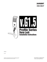
Installation Instructions For
Profile Series Hardwired Networked
v.S1 Cylindrical Lock

Table of Contents
This device complies with Part 15 of the FCC Rules. Operation is subject to the following two conditions: (1) this
device may not cause harmful interference, and (2) this device must accept any interference received, including
interference that may cause undesired operation.
Note: This equipment has been tested and found to comply with the limits for a Class B digital device, pursuant to
Part 15 of the FCC Rules. These limits are designed to provide reasonable protection against harmful interference in
a residential installation. This equipment generates, uses and can radiate radio frequency energy and if not installed
and used in accordance with the instructions, may cause harmful interference to radio communications. However,
there is no guarantee that the interference will not occur in a particular installation. If this equipment does cause
harmful interference to radio or television reception, which can be determined by turning the equipment off and on,
the user is encouraged to try to correct the interference by one or more of the following measures:
• Reorient or relocate the receiving antenna
• Increase the separation between the equipment and receiver
• Connect the equipment into an outlet on a circuit different from that to which the receiver is connected
• Consult the dealer or an experienced TV technician for help
This Class B digital apparatus complies with Canadian ICES-003.
Cet appareil numérique de la classe B est conforme avec la norme NMB-003 du Canada.
Warning
1
Warning: Changes or modifications to this unit not expressly approved by the party
responsible for compliance could void the user's authority to operate the equipment.
Warning
General Description.....................................................1
Specifications............................................................1
Features ..................................................................1
Parts Breakdown .......................................................2-3
Installation Instructions...............................................4-9
Operational Check......................................................10
1
2
3
4
5
6
7
Page
Warning
!
To comply with “Fire Listed” doors, battery operated units must be replaced with alkaline
batteries only.
For installation assistance, contact SARGENT at 800-810-WIRE (9473)

1
For installation assistance, contact SARGENT at 800-810-WIRE (9473)
The SARGENT Profile Series v.S1 Keypad Cylindrical Lock is designed for areas which require stand alone
authorized entry. It is a self-contained microprocessor-controlled keypad with non-volatile memory. The keypad will
hold a total of 2000 (S1-LU, S1-PK, S1-PA) different user codes.
This product is operated by six (6) “AA” alkaline batteries or by the SARGENT 3267 9VDC power supply.
General Description
2
Specifications
• Latch – 1/2" standard
3/4" throw fire-rated double doors
(optional) (41- prefix)
• Deadlocking latch
• Outside lever controlled by keypad,
or key retracts latch
• Inside lever retracts latch
• Locks furnished for 1-3/4" doors only
• U.L. Listed
Features
• Non volatile memory
• Motor driven, battery operated
• Battery operated with 6 “AA” alkaline batteries
• Low battery alert–4 chirps after code entry
• Optional external power, sargent 3267 9vdc
power supply
• External remote “request to enter”
• Master, Emergency or Supervisory code will unlock
door when low battery has expired
• 2000 (S1-LU, S1-PK, S1-PA) users
• Programming is done at a central computer for
monitoring and access control of each door via a
gateway and network wiring using TekControl™
software
• Pin Code, Proximity Card, Fob are optional
• Operates utilizing any two to six digits per code. Digits
may be repeated and codes may start with zero
• Cylinder override
• Entry of three wrong User Codes disables all codes
for ten seconds. Yellow LED on solid
• Piezo horn can be heard with each keystroke or
turned off by Master or Supervisory Code
3
4
Profile Series v. S1 Cylindrical Lock
TEKControl Software
Data (RS232)
TEKLock 4200
Access Control Server
(Gateway)
120VAC L/N/G
Ethernet LAN
Network
Interface
Card
Profile
Series
v. S1
1
2
3

2
Parts Breakdown
For installation assistance, contact SARGENT at 800-810-WIRE (9473)
5
Profile Series v. S1 Cylindrical Lock
1
17
21
Optional
21
21
10
11
13
15
6
2
7
12
18
16
9
14
7
21
3
25
23
5
24
19
4

3
For installation assistance, contact SARGENT at 800-810-WIRE (9473)
Profile Series v. S1 Cylindrical Lock
ITEM PART No. DESCRIPTION REQ’D
1 10-2000 2-3/4" Backset Latch (Standard) 1
10-2053 3-3/4" Backset Latch (23 Prefix) 1
10-2058 5" Backset Latch (25 Prefix) 1
10-2634 3/4" Throw (41 Prefix) 1
2 10-3136 Outside Escutcheon Key Pad, Key Pad/Prox (S1-LU, S1-PK) 1
10-3137 Outside Escutcheon Prox Only (S1-PA) 1
10-3016 Outside Escutcheon Housing Only 1
52-2432 Key Pad/Proximity Bezel Assembly w/ Harness (S1-LU, S1-PK) 1
52-2431 Prox Only Bezel Assembly w/ Harness/(S1-PA) 1
3 10-3132 Inside Escutcheon and 2000 User Controller (S1-LU) 1
10-3133 Inside Escutcheon and Key Pad/Prox or Prox Only Controller (S1-PA, S1-PK) 1
10-3015 Inside Escutcheon Housing Only 1
52-2891 2000 User Key Pad Controller Assembly (S1-LU) 1
52-2892 2000 User Prox Only or Prox Key Pad Controller Assy. (S1-PA, S1-PK) 1
4 10-0523 “B” Inside Lever/Passage 1
10-2204 “J” Inside Lever/Passage
NOTE: Coastal Levers & Cylinders other than Standard— See 10 Line Parts Pages
1
10-0501 “L” Inside Lever/Passage 1
10-0545 “P” Inside Lever/Passage 1
10-0534 “B” Inside Lever (75- Handicap Warning) 1
10-2245 “J” Inside Lever (75- Handicap Warning) 1
10-0512 “L” Inside Lever (75- Handicap Warning) 1
10-0556 “P” Inside Lever (75- Handicap Warning) 1
5 52-0170 Battery Cover Only 1
6 10-0019 Cylinder Spacer 1
7 10-0792 Spacer Bushing 2
9 10-3048 Inside Rose Spring Assembly 2
10 10-0524 “B” Outside Lever Standard Cylinder 1
10-2205 “J” Outside Lever Standard Cylinder 1
10-0502 “L” Outside Lever Standard Cylinder 1
10-0546 “P” Outside Lever Standard Cylinder 1
10-0525 “B” OutsideLever (30- To Accept Schlage Cylinder) 1
10-2206 “J” Outside Lever (30- To Accept Schlage Cylinder) 1
10-0503 “L” Outside Lever (30- To Accept Schlage Cylinder) 1
10-0547 “P” Outside Lever (30- To Accept Schlage Cylinder) 1
10-1535 “B” Outside Lever Standard Cylinder (76- Handicap Warning) 1
10-2246 “J” Outside Lever Standard Cylinder (76- Handicap Warning) 1
10-0513 “L” Outside Lever Standard Cylinder (76- Handicap Warning) 1
10-0557 “P” Outside Lever Standard Cylinder (76- Handicap Warning) 1
11 Key (Provided with Cylinder)
12 10-3049 Outside Rose Spring Assembly 1
13 13-3266 Cylinder (Standard) 1
13-3613 Schlage (SC) Cylinder (95-(SC)) 1
13-3614 Schlage (SE) Cylinder (95-(SE)) 1
10-0019 Schlage (SC, SE & Signature) Cylinder Spacer 1
13-3491 Cylinder (22-Construction) 1
13-3713 Cylinder (10-Signature) 1
13-3871 Cylinder (10-21 Signature Construction) 1
13-3944 Cylinder (21-Cylinder) 1
18-4020 Cylinder (VA-ASSA V10) 1
18-4063 Cylinder (VS-ASSA V10) 1
14 01-9170 Screws for Through-Bolts (#10-32 x 1-3/4") 1
15 10-0312 Cylinder Retainer - All Cylinders except Removeable and Interchangeable core 1
10-0313 Cylinder Retainer - Removeable Core or Interchangeable Core 1
16 10-2642 77 Lock Body (Std, 10, 21, 23, 30, SC, SE, VA & VS Prefixes only) 1
10-2643 77 Lockbody (60, 63, 64 Prefixes only) 1
10-2644 77 Lockbody (70, 72, 65-73, 65-73P Lockbody) 1
17 08-0312 #800 Strike 1
08-0066 #808 Strike (28-Prefix) 1
18 52-0033 Fire Stop Plate and Screws (2) 1
19 45-1340 Flat Head Screw (Security) 1
20 52-2300 Screw Pack (includes item #’s 18, 19, 24, 25) 1
01-0297 1/8" Security Socket Allen Wrench (item 24) 1
21 10-2052 Screw Pack – Specify Finish (Strike Screws, Latch Screws, Push Pin Tool, Strike Box) 1
23 52-0253 Battery Keeper 1
24 See Item # 20 Screw Pack
25 See Item # 20 Screw Pack
26 52-3010 Power/Data Cable (Not Shown) 1
27 52-3211 Door Position Harness (Not Shown) 1
28 52-2847 Weather Conduit (Not Shown) 1

Installation Instructions
6
Profile Series v. S1 Cylindrical Lock
4
For installation assistance, contact SARGENT at 800-810-WIRE (9473)
1. Verify Hand and Bevel of Door
Stand on outside/locked side of the door when determining the door hand
2. Door Preparation
Prepare door according to appropriate template
(see website www.sargentlock.com):
• For metal door template, see 4531 and 4532
• For wood door template, see A7456, A6719D and 4540A
• Prior to installation, all holes must be free of burrs, debris
and sharp edges
• If doors are not properly reinforced per ANSI115.2,
commercially available reinforcements
should be installed
Wood Door Preparation
1-1/2"
(2) 1/8" Dia. holes
required
7/8"
Through-bolt
hole (2)
C
L
of
1-1/2" Dia.
Lockbody
hole
Latchbolt
door prep
Pre-drilled
and/or tapped
holes 2 places
Inside
of door
Outside
of door
Hole for ribbon
cable from keypad
to controller

5
Profile Series v. S1 Cylindrical Lock
For installation assistance, contact SARGENT at 800-810-WIRE (9473)
3. Frame Preparation for Strike
Screws (2)
#8-32 x 3/4"
Centerline of
latch front and
strike
Non Fire Rated Exterior Doors–
Install Weather Conduit (P/N 52-2847)
as shown below
4. Latchbolt and Fire Stop Plate Installation
1. Install latch with beveled bolt facing the strike.
2. Attach with two screws but DO NOT tighten completely at this time.
3. Attach Fire Stop Plate with two screws.
Note: Required for all Fire Rated doors
1-1/2"
(2) 1/8" Dia. holes
required
7/8"
Fire
stop plate
Through-bolt
hole (2)
(2) Self tapping
screws #8 x 1/2"
long for wood
& metal doors
Slot
C
L
of
1-1/2" Dia.
IMPORTANT: Latch bevel must match door bevel and
deadlocking latch must stop on strike when door is closed
Fire Rated Doors– Install Fire
Stop Plate (P/N 52-0033)
as shown below
Strike
Deadlockin
g
latch

6
For installation assistance, contact SARGENT at 800-810-WIRE (9473)
Profile Series v. S1 Cylindrical Lock
Screws partially
tightened
For wood
door only
Inside
of door
1
2
Lock Preset to:
• Through-bolt location– 12 & 6 o'clock
• Door thickness– 1-3/4" thick- see below for other door conditions
Adjustment for different through-bolt and door thickness:
• Through-bolt location– rotate outside rose to match door
• Door thickness– rotate outside rose to align door thickness marking with lockbody edge
• Spacer bushing– remove and realign to fit into back of lever
5. Lock Installation
IMPORTANT:
Door must remain open
during installation.
Use door stop.
3
1-3/4" thick door
2" thick door
Through-bolt
holes
Rotate to match
through-bolt holes in d
o
Spacer b
u
1. Feed wires into the lock body hole, from outside of door.
2. Lock body into cross-bore hole from outside of the door (locked side).
3. Lock body must engage both the latch unit prongs and tail piece, as shown.
IMPORTANT:
Lockbody
must be centered
in the door

7
For installation assistance, contact SARGENT at 800-810-WIRE (9473)
Profile Series v. S1 Cylindrical Lock
1. Insert key, rotate 45° clockwise and hold.
2. Depress lever retainer with push pin tool (provided).
7. Remove Outside Lever Only
1. With outside lever in hand- use standard
pliers, pull out cylinder retainer.
2. Remove key and cylinder from lever.
3. Insert new cylinder.*
4. Secure by pressing cylinder retainer
flush with self.*
* NOT SHOWN
How to Change Cylinder
(if required)
Washers
(only 30- prefix)
Cylinder
retainer
Cylinder
Outside
lever
Key
Cylinder
spacer
45°
2
1
Feed wires and
connector if
wood door
Routed channel for
wood door only
Screws
partially
tightened
2
1A
1A. If wood door, feed wires up through the
routed channel as shown.
1B. If metal door, feed wire and connector
through inside of door and out hole on
outside of door. *
2. Attach inside rose assembly and
spacer bushing and secure with
screws shown.
6. Securing the Lock to Door

8
For installation assistance, contact SARGENT at 800-810-WIRE (9473)
Profile Series v. S1 Cylindrical Lock
NOTE: For exterior applications, use weather seal gasket part
# (10-0649) between escutcheon and outside door surface
1A. For fir
e rated doors only feed ribbon cable connector and
ground wire from outside of door through weather seal gasket
(if used) then fire stop plate.
1B. For non-fir
e rated doors only, feed ribbon cable connector
and ground wire from outside of door through weather seal
gasket (if used), then conduit sleeve in door (not shown).*
2. Slide the outside escutcheon over the lock, and hold
the escutcheon to the door surface.
3. Verify white plastic cylinder spacer is inserted into horizontal
slot of lockbody.*
4. Slide the outside lever onto tube with key horizontal (toward
latch). Rotate key 45 degress clockwise.
5. Push lever until lever catch is engaged.
Inside lever
Inside of
door
Inside rose
8-32 Flat head
screw
Lockbody
harness
Keypad
harness
Ground
wire
Outside of
door
Ground
wire
Weather
Seal
Gasket
Latch
screws
2
1A
5
8. Installation of Outside Escutcheon and Lever
9. Inside Escutcheon and Lever
1. Remove black battery cover from the escutcheon with security wrench (provided).
2. Connect ground wire to terminal E3 (Fig. 1), connect keypad harness (Fig. 2) to controller, and connect lock
body motor harness (Fig. 3) to motor connector.
3. Feed all excess wire through inside door hole and/into outside escutcheon cavity, being careful not to pinch wires.
NOTE: Connectors go on only one way, do not offset connector and be sure they are completely sealed.
4. Insert two #8-32 screws (Fig. 2) through top and bottom of inside escutcheon and thread into outside escutcheon.
Straighten escutcheons and tighten securely, being careful to avoid pinching wires.
5. Slide the Inside Lever onto the tube.
6. Tighten two latch screws completely.
Figure 1
Figure 3
Figure 2
* NOT SHOWN
4
/