Page is loading ...

Installation Instructions For
Persona Passport 1000 Mortise Lock
A7807H
www.sargentlock.com
© SARGENT Manufacturing Company 2006
7807A_A7454C Low Profile Mortise Lock.indd 1 9/26/18 2:54 PM

Table of Contents
Warning
General Description ............................................................ 1
Mortise Lockbody Specifications ........................................ 1
Electronics Specifications .................................................. 1
Parts Breakdown/Parts Table............................................2-3
Installation Instructions .....................................................4-10
Operational Check ............................................................. 10
Lockset Programming .....................................................11-12
Page
For installation assistance, contact SARGENT at 800-810-WIRE (9473)
1
2
3
4
5
6
7
8
This device complies with Part 15 of the FCC Rules. Operation is subject to the following two conditions: (1) this
device may not cause harmful interference, and (2) this device must accept any interference received, including
interference that may cause undesired operation.
Note: This equipment has been tested and found to comply with the limits for a Class B digital device, pursuant to
Part 15 of the FCC Rules. These limits are designed to provide reasonable protection against harmful interference in
a residential installation. This equipment generates, uses and can radiate radio frequency energy and if not installed
and used in accordance with the instructions, may cause harmful interference to radio communications. However,
there is no guarantee that the interference will not occur in a particular installation. If this equipment does cause
harmful interference to radio or television reception, which can be determined by turning the equipment off and on,
the user is encouraged to try to correct the interference by one or more of the following measures:
• Reorient or relocate the receiving antenna
• Increase the separation between the equipment and receiver
• Connect the equipment into an outlet on a circuit different from that to which the receiver is connected
• Consult the dealer or an experienced TV technician for help
This Class B digital apparatus complies with Canadian ICES-003.
Cet appareil numérique de la classe B est conforme avec la norme NMB-003 du Canada.
Warning
1
Warning: Changes or modifications to this unit not expressly approved by the party
responsible for compliance could void the user’s authority to operate the equipment.
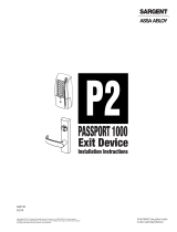
Warning
!
To comply with “Fire Listed” doors, the batteries must be replaced with alkaline batteries only.
7807A_A7454C Low Profile Mortise Lock.indd 2 9/26/18 2:54 PM

1
For installation assistance, contact SARGENT at 800-810-WIRE (9473)
Persona Passport 1000 Mortise Lock
The SARGENT Passport 1000 Mortise Lock is designed to accommodate the University market. The product is
available as an Offline stand alone unit. Available access interface is keypad and magstripe card. The lock may be
used in both indoor and outdoor applications. Note that a weather protective gasket is recommended for the outdoor
applications.
The Persona Passport 1000 Offline version is a new breed of electronic lock providing offline card access control.
This product is operated by six (6) “AA” alkaline batteries. SARGENT mortise locks are designed with quality
components to provide high security, performance and durability.
General Description
2
Mortise Lockbody Specifications
• Latch - Stainless steel
• Deadbolt - Stainless steel
• Guardbolt - Stainless steel, non handed
• Handed - Easily field reversible without
disassembling the lock body
• Case - 12 gauge heavy duty wrought steel
• Outside lever controlled by any combination of keypad
or proximity magstripe keypad, or mechanical cylinder
• Inside lever retracts latch and deadbolt
• Locks furnished for 1-3/4” doors. Can be
furnished for other door sizes upon request.
Consult factory
• U.L. Listed (3 hr.)
Electronics Specifications
Offline Electronics Specifications
• 1,048,576 programmable users
• 700 event transaction audit trail
• Multiple time zone and holiday access scheduling
• First-In unlock configuration, either by time or by valid
time or by user (selectable)
• Input Power: DC 9V, 1.5A (6 AA Alkaline Batteries or
Electrical Power)
3
4
7807A_A7454C Low Profile Mortise Lock.indd 1 9/26/18 2:54 PM

2
4
1
31
32
33
34
35
36
37
21
30
23
22
24
2
26
38
6
7
8
9
10
11
19
20
12
7
6
5
1718
28 29
13
14
25
16
15
3
39
27
For installation assistance, contact SARGENT at 800-810-WIRE (9473)
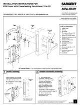
Persona Passport 1000 Mortise Lock
5
Parts Breakdown
7807A_A7454C Low Profile Mortise Lock.indd 2 9/26/18 2:54 PM

3
For installation assistance, contact SARGENT at 800-810-WIRE (9473)
Persona Passport 1000 Mortise Lock
5
Parts Breakdown Table
ITEM PART No. DESCRIPTION REQ’D
1 82-0642 Outside Escutcheon with Keypad and Card Reader 1
1 82-0643 Outside Escutcheon with Cylinder Hole, Keypad and Card Reader (Shown) 1
1 82-0644 Outside Escutcheon with Card Reader 1
1 82-0645 Outside Escutcheon with Card Reader and Cylinder Hole 1
2 82-4506 Inside Escutcheon Assembly with Turn Lever 1
2 82-0647 Inside Escutcheon Blank 1
2 82-4507 Inside Escutcheon Assembly with Turn Lever and RF Window (Shown) 1
2 82-0649 Inside Escutcheon with RF Window 1
3 Cylinder & Key Assembly 1
4 (Outside Lever) Reference Persona catalog for available lever handles 1
5 (Inside Lever) Reference Persona catalog for available lever handles 1
6 82-0347 Spindle Spring
7 82-0368 Spindle
8 81-0723 Mounting Post 2
9 01-0079 Washer 2
10 82-3082 Adapter & Plate Assembly 1
11 82-0184 Cap Nut 1
12 01-1028 Face Plate Screws Machine 8-32 x 1/4” 2
13 82-0578 Face Plate with Latchbolts/Auxiliary Windows 1
14 82-0579 Face Plate with Latchbolt/Deadbolt/Auxiliary Windows (Shown) 1
15 01-2299 Lock Body Screws/Wood Door #12 x 1-1/4” 2
16 01-1019 Lock Body Screws/Metal Door 12-24 x 1/2” 2
17 82-4467 Lock Body Assembly (with deadbolt) (82276 & 82277) (Shown) 1
18 82-4468 Lock Body Assembly (without deadbolt) (82278 & 82279) 1
19 82-3088 Inside Spindle Adapter & Plate Assembly 1
20 01-1495 Screw #8-32 x 1/2” 2
21 52-3125 Battery Pack Assembly P1-Prefix 1
21 52-3126 Battery Pack Assembly P2-Prefix 1
21 52-3127 Battery Pack Assembly PG-Prefix 1
22 01-1119 Screw #8-32 x 1-1/2” Phillips Flat Head MS 2
23 01-1141 Screw #8-32 x 3/8” Phillips Flat Head 1
24 01-9214 Screw #4-40 x 1/8” Phillips Pan Head MS 4
25 52-0530 RF Escutcheon Cover 1
26 01-1428 Security Screw #8-32 x 3/8” Pinhead TORX FL HD Machine Screw
27 01-1371 Screw #8-32 x 1 7/8” Pinhead TORX FL HD Machine Screw
28 01-1426 Lever Handle Set Screw TORX Pinhead 1/4-28 x .1875”
29 01-4405 Lever Handle Set Screw TORX Pinhead 1/4-28 x .25”
30 52-0634 Retaining Ring 1
31 52-0653 Gasket
31 52-3069 Keypad Assembly 1
32 01-9221 4-40 x 5/16 PH PAN HD Machine Screw 4
33 52-3071 Card Reader Assembly 1
34 01-1142 8-32 x 1/4 PH HD Machine Screw 1
35 01-9213 4-40 x 5/16 PH FL HD Machine Screw 2
36 52-3093 Outside Fixed Plate Assembly 1
37 01-4402 8-32 x 7/16 PH FL HD Machine Screw 4
38 01-0297 TORX Pin HD Socket Key 1
39 52-0634 Grounding Assembly 1
40 52-0653 Gasket (Not Shown, See Page ?) 1
7807A_A7454C Low Profile Mortise Lock.indd 3 9/26/18 2:54 PM

4
For installation assistance, contact SARGENT at 800-810-WIRE (9473)
Persona Passport 1000 Mortise Lock
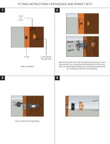
Left Hand
Hinges Left.
Open inward.
“LH”
Left Hand
Reverse Bevel
Hinges Left.
Open Outward
“LHRB”
Right Hand
Hinges Right
Open Inward.
“RH”
Right Hand
Reverse Bevel
Hinges Right.
Open Outward.
“RHRB”
View lock body from top and from the outside (as shown above)
Bevel
Latchbolt
Right Hand
Right Hand
Reverse Bevel
Left Hand
Reverse Bevel
Lock Body
Verify hand and bevel of door
Connector and Wires
Deadbolt
Guardbolt
Latchbolt
Front
Top
Lock w/cylinder
Override
(Shown)
End Cap
Installation Instructions
6
Verify Hand and Bevel of Door
Wood door - A7800
Metal door - 4576
Step #1 – Door
Preparation
Inside of Door
Hole for cable
from keypad to
controller
Left Hand
Hinges Left.
Open Inward.
“LH”
Right Hand
Hinges Right.
Open Inward.
“RH”
Left Hand
Reverse Bevel
Hinges Left.
Open Outward
“LHRB”
Right Hand
Reverse Bevel
Hinges Right.
Open Outward
“RHRB”
Thru-bolt hole
Thru-bolt hole
Thru-bolt hole
Mortised
area
Outside cylinder
hole
Lever handle hole
Inside cylinder hole
Thumb turn lever hole
Lever handle hole
Outside of Door
7807A_A7454C Low Profile Mortise Lock.indd 4 9/26/18 2:54 PM

5
For installation assistance, contact SARGENT at 800-810-WIRE (9473)
Persona Passport 1000 Mortise Lock
Step #2 – How to Reverse Lock
Hand
Note: Beveled surface of latch must face strike. The deadlatch is self adjusting.
To change hand of latch:
1. Insert screwdriver blade into the spade shaped slot
2. Rotate screwdriver 90º to push latch out until back of latch clears lock front.
Then rotate latch 180º. Latch will then re-enter lockbody.
(Note: Latch can not be unscrewed)
Note: Red surface of locking piece must face secure side of door.
To rotate locking piece:
1. Position lockbody with red surface of locking piece visible
2. Insert blade type screwdriver into locking piece slot to rotate locking piece
3. Push locking piece toward back of lock body and rotate 180° until RED
surface shows on opposite side
4. Red indicates locked (outside) side.
5. Wire harness MUST exit thru non-cylinder side.
Locking guide
slot
Connector
End cap
RED color
locking piece
indicates locked
side
Connector and
wires
Front
Deadbolt
Latchbolt
Dead latch
Outside of Door
End cap
Latchbolt
Triangular slot
Rotate
Push in
Right Hand
Shown
7807A_A7454C Low Profile Mortise Lock.indd 5 9/26/18 2:54 PM

6
For installation assistance, contact SARGENT at 800-810-WIRE (9473)
Persona Passport 1000 Mortise Lock
Step #3 – Lockbody Installation
Wires and connector go into the mortised area and out of the inside cylinder hole
Step #4 – Gasket Installation
Note: Optional (Non-fire rated)
1. For non-fire rated door applications,
an optional gasket may be used as a
weather seal between the escutcheon
and the outside door surface.
2. Feed keypad/card reader connector
cable, programming connector cable, and
the grounding harness through gasket
then through hole in door.
Inside of Door
Must feed
connector &
wires through
non-cylinder
side
Insert lockbody in mortised cutout
Hold loosely in place with (2) lockbody screws
DO NOT COMPLETELY TIGHTEN SCREWS
AT THIS TIME
(2) #12 X 1-1/4” long flat
head wood screw for wood
doors
Mortise lockbody
connector & wire
(2) #12-24 X 1/2”
long flat head
screw for metal
doors
7807A_A7454C Low Profile Mortise Lock.indd 6 9/26/18 2:54 PM

7
For installation assistance, contact SARGENT at 800-810-WIRE (9473)
Persona Passport 1000 Mortise Lock
Step #5 – Installation of Outside Escutcheon & Inside Spindle Adapter
1. With outside lever horizontal, insert
mounting posts through door and lock
body. Make certain the lever spindle is
properly engaged in lock.
2. Insert spindle into square hole of
mortise lockbody.
3. Slide plate assembly over spindle and
secure to the door using thru-bolt posts
with (2) #8-32 screws. Do not tighten
completely, cylinder should be installed
prior to tightening.
Keypad/card reader
connector
Programming connector
Keypad/card reader
connector
Plate
Assembly
Grounding Harness
Grounding Harness
Programming connector
Outside of Door Inside of Door
Outside spindle
Inside
spindle
Screw
(2) #8-32 X 1/2”
Mortise Lockbody Connector
Step #6 – Installation of Cylinder
1. Align cylinder (as shown in Fig. 1).
2. Screw cylinder into lockbody unit (Ref. Fig. 3 for cylinder orientation).
3. Test key in the cylinder to make certain that the locking mechanism functions
correctly. If not, unscrew cylinder 1 full turn and retest.
4. Tighten the set screw to prevent unscrewing of the cylinder (Ref. Fig. 2).
5. Tighten lockbody screws completely at this point followed by the #8-32
thru-bolting screws.
Fig. 1
Fig. 3
Fig. 2
Inside of
door
•
Set
screw
Inside lever
Outside of door
Type 43 Mortise
cylinder ONLY
Key
SARGENT
SARGENT
Note: Key and
cylinder must be
rotated as shown
Correct Incorrect
Phillips
screwdriver
Set screw
Spindle
Key
Type 43 Mortise
cylinder ONLY
Phillips
Screwdriver
#8-32 Thru-bolting
screws on other side
Lockbody
screw
Set Screw
Outside of Door
Note: Key and cylinder
must be rotated as
shown
Correct Incorrect
Note: Cylinder
must turn without
interference.
7807A_A7454C Low Profile Mortise Lock.indd 7 9/26/18 2:54 PM

8
For installation assistance, contact SARGENT at 800-810-WIRE (9473)
Persona Passport 1000 Mortise Lock
Secure the following connectors onto the circuit board as shown in Fig. 1. Mate keys on connectors such that
connector inserts into header with proper orientation.
1. Secure the mortise lockbody assembly connector (10 Pin)
(as shown in Fig. 2).
2. Secure the mortise keypad/card reader connector (24 Pin)
(as shown in Fig. 3).
3. Secure the programming connector (8 Pin)
(as shown in Fig. 4).
NOTE: Connectors go on only one way, do not offset
connector and be sure they are completely seated.
Keypad/card
reader connector
Programming
connector
Mortise
lockbody
connector
Step #8 – Installation of Connectors
Fig. 1
Fig. 2
Fig. 4Fig. 3
Step #7 – Installation of Fixed Hinge Plate
Battery pack
assembly
Screw #8-32 x
1-1/2”
Fixed hinge plate
Attach the fixed hinge plate to the outside escutcheon using (2) #8-32 X 1-1/2” screw.
Straighten escutcheon and tighten securely.
Caution: Be careful not to damage harnesses or pinch wires while attaching fixed hinge plate.
7807A_A7454C Low Profile Mortise Lock.indd 8 9/26/18 2:54 PM

9
For installation assistance, contact SARGENT at 800-810-WIRE (9473)
Persona Passport 1000 Mortise Lock
(6) 1.5 V “AA”
Alkaline battery
Screw #6-32 X 3/8”
Battery pack assembly
Grounding
Harness
Retaining
Ring
(-) Polarity
(+) Polarity
Place (6) “AA” batteries into the
compartment being careful to align
polarity properly
1. Fold the battery pack assembly upright and use a
#6-32 X 3/8” screw to attach to the fixed hinge plate.
2. Be sure to attach the grounding harness and retaining
ring through the screw (#6-32 X 3/8”).
Note: Place extra wire inside door hole.
Step #9 - Battery Installation/Battery Pack Assembly Attachment
Security screw
#8-32 X 3/8”
Security tool
Inside of Door
Screw #8-32 X 2”
Inside Escutcheon
1. Insert #8-32 X 2” screw through inside escutcheon and thread into outside escutcheon. Straighten escutcheon and
tighten securely.
2. Be sure to align the turn lever into the mortise lockbody until fully seated.
3. Insert the #8-32 X 3/8” screw using security tool through inside escutcheon and thread into the fixed hinge plate.
Note: All wires should be placed inside to avoid being pinched
Step #10 - Installation of Inside Escutcheon
7807A_A7454C Low Profile Mortise Lock.indd 9 9/26/18 2:54 PM

10
For installation assistance, contact SARGENT at 800-810-WIRE (9473)
Persona Passport 1000 Mortise Lock
Step #12 – Application of Front Plate
1. Attach front plate with (2) #8-32 X 1/4” flat head screws.
Outside of Door
Lockbody
screws
Front plate
(2) Screw #8-32 X 1/4”
Operational Check
7
For devices with cylinders:
1. Insert key into cylinder and rotate (There should be no friction against lock case,
wire harness or any other obstructions – refer to Section 6, Step 10 if harness
friction exists.
2. The key will retract the latch, key should rotate freely
3. If the deadbolt is thrown, the key will retract both the deadbolt and the latch
4. Inside lever retracts latch and deadbolt (if provided)
After programming the new lockset, verify operation by inserting the mag strip card or
by pressing the keys.
CARD READER INSERTION VIEW
Step #11 – Installation of Inside Lever
1. Put the turn lever in the horizontal position
(Ref. Fig. 1).
2. Slide lever handle onto spindle until fully seated (as
shown in Fig. 2). Be sure handle is horizontal and
facing to the rear of the door.
3. Tighten the set screw securely with 1/8” hex wrench.
Fig. 1
Fig. 2
Inside of Door
Inside lever
Lever handle
screw
Spindle
7807A_A7454C Low Profile Mortise Lock.indd 10 9/26/18 2:54 PM

11
For installation assistance, contact SARGENT at 800-810-WIRE (9473)
Persona Passport 1000 Mortise Lock
Step #1 – Lockset Programming
1. Starting the Pocket PC LockLink™ Software
• Touch the “Start” button on the Pocket PC Screen:
2. Logging into the LockLink™
• Select your username from the list that appears
• If visible, select “PERSONA Locklink” to launch the
program.
• Otherwise, click “Programs” to launch the Programs list
and then select the PERSONA LockLink™ icon:
7807A_A7454C Low Profile Mortise Lock.indd 11 9/26/18 2:54 PM

12
For installation assistance, contact SARGENT at 800-810-WIRE (9473)
Persona Passport 1000 Mortise Lock
Type in your password. You can use the Windows keyboard or the full
screen applet provided. To access the full screen keyboard, tap on the
three dots next to the password field, as shown:
3. Once you have entered your password, you will begin
on the “Upload” screen. This is the proper place to be for
programming locks.
4. Tap on the lock’s name that you wish to program and
highlight it. Tap the button: to completely initialize the lock. If
the list of locks is very long, you can use the button to search
for a particular lock.
5. You will be prompted to insert the Contact Card into the lock.
You will be prompted twice more to remove and then reinsert
the Contact Card. Simply follow the directions shown on the
screen.
6. When the data has finished copying, remove the Contact
Card from the lock. (An asterisk will appear before each lock
name that has been programmed along with the date and
time that the lock was programmed).
7. Repeat this procedure for each lock to be programmed with
lock data.
7807A_A7454C Low Profile Mortise Lock.indd 12 9/26/18 2:54 PM
/