Page is loading ...

General Safety Instructions
1) Work area safety
a) Keep work area clean and well lit. Cluttered or dark areas invite accidents.
b) Don’t use power tools in a dangerous environment. Don’t use power tools in
damp or wet locations, or expose them to rain.
c) Do not operate power tools in explosive atmospheres, such as in the presence
ofammableliquids,gasesordust. Power tools create sparks that can ignite the
fumes or dust.
d) Keepchildrenandbystandersawaywhileoperatingapowertool.Distractions c
an cause you to lose control.
e) Make your workshop child proof. Use padlocks, master switches, or remove
starter keys.
2) Electrical safety
a) Groundelectrictools.Ifthetoolisequippedwithathree-prongplug,itmust
bepluggedintoagroundedthree-holeelectricaloutlet. If the proper outlet is not
available,haveoneinstalledbyaqualiedelectrician.Neverremovethethirdprongor
modify the provided plug in any way.
b) Do not expose power tools to rain or wet conditions. Water entering a power tool
increases the risk of electric shock.
c) Donotabusethecord.Neverusethecordforcarrying,pullingorunpluggingthe
power tool. Keep cord away from heat, oil, sharp edges or moving parts. Damaged
or entangled cords increase the risk of electric shock.
d) Use a proper extension cord and make sure it is in good condition. When
using an extension cord, be sure to use one heavy enough to carry the current your
power tool draws. An undersized cord causes a drop in line voltage resulting in loss of
power and overheating. Table1 on the following page shows the correct cord gauge to
use depending on cord length and tool nameplate ampere rating. If in doubt, use the
next heavier gage. The smaller the gauge number, the heavier the cord.
e) Whenoperatingelectrictools,avoidbodycontactwithgroundedorearthed
surfaces such as pipes, radiators, kitchen ranges, and refrigerators. Contact with a
grounded surface increases the risk of electric shock.
3) Personal safety
a) Stay alert, watch what you are doing and use common sense when operating
apowertool.Donotuseapowertoolwhileyouaretiredorundertheinuence
of drugs, alcohol or medication. A moment of inattention while operating power tools
can result in serious personal injury.
b) Always wear safety glasses. Everyday eyeglasses are not safety glasses. Safety
glasses have specially constructed lenses, frames, and side shields.
c) Usesafetyequipment. Use a face or dust mask when the cutting operation is
dusty. Safety equipment such as a dust mask, non-skid safety shoes, hard hat, or
hearing protection used for appropriate conditions reduces personal injuries.
d) Avoidaccidentalstarting.Makesuretheswitchisintheoff-positionbefore
plugging in.Carryingpowertoolswithyourngerontheswitchorplugginginpower
tools that have the switch on invites accidents.
e) Removeanyadjustingkeyorwrenchbeforeturningthepowertoolon.A
wrench or a key left attached to a rotating part of the power tool can result in personal
injury.
f) Donotoverreach.Keepproperfootingandbalanceatalltimes. This enables
better control of the power tool in unexpected situations.
g) Secure workpieces. Use clamps or a vise to hold work when practical. This is safer
than using your hand and it frees both hands to operate the tool.
h) Neverstandonthemachine. Serious injury can occur if the tool tips or if the cutting
tool is unintentionally contacted.
i) Dress properly. Do not wear loose clothing or jewelry. Keep your hair, clothing
and gloves away from moving parts. Loose clothes, jewelry or long hair can be
caught in moving parts. Roll up long sleeves to the elbow. Wear protective hair covering
to contain long hair.
j) If devices are provided for the connection of dust extraction and collection
equipment,ensuretheseareconnectedandproperlyused.Use of these devices
reduces dust-related hazards.
4) Power tool use and care
a) Keep guards in place and in working order.
b) Do not force the power tool. Use the correct power tool for your application.
The correct power tool will do the job better and safer at the rate for which it was
designed.
c) Use the right tool. Don’t force a tool or attachment to do a job for which it was not
designed.
d) Do not use the power tool if the switch does not turn it on and off. Any power
tool that cannot be controlled with the switch is dangerous and must be repaired.
e) Disconnecttheplugfromthepowersourceand/orthebatterypackfromthe
powertoolbeforemakinganyadjustments,changingaccessories,orstoring
power tools. Such preventive safety measures reduce the risk of starting the power
tool accidentally.
f) Neverleaveatoolrunningunattended.Turnpoweroff. Don’t leave the tool until it
comes to a complete stop.
g) Store idle power tools out of the reach of children and do not allow persons
unfamiliar with the power tool and these instructions to operate the power tool.
Power tools are dangerous in the hands of untrained users.
h) Maintainpowertools.Checkformisalignmentorbindingofmovingparts,
brokenparts,andanyotherconditionthatcanaffectpowertooloperation.If
damaged,havethepowertoolrepairedbeforeuse. Many accidents are caused by
poorly maintained power tools.
i) Keep cutting tools sharp and clean. Properly maintained cutting tools with sharp
cutting edges are less likely to bind and are easier to control.
j) Use the recommended speed for the cutting tool or accessory and workpiece
material.
k) Onlyusepartsandaccessoriesrecommendedbythemanufacturer.Consult
the owner’s manual for recommended accessories. Using improper accessories can
cause personal injury.
l) Usethepowertool,accessories,andtoolbitsinaccordancewiththese
instructions and in the manner intended for the particular type of power tool,
takingintoaccounttheworkingconditionsandtheworktobeperformed. Use
of the power tool for operations different from those intended can result in a hazardous
situation.
5) Service
a) Haveyourpowertoolservicedbyaqualiedrepairpersonusingonlyidentical
replacement parts. This ensures that the safety of the power tool is maintained.
6) Safety instructions specic to using a router table tted with the
Precision Router Table Fence
a) Read, understand, and follow your router manufacturer’s safety warnings
and instructions.
b) Disconnecttherouterfrompowerbeforemakingadjustments.Neveradjust
the fence, plate, reducing rings, or any part of the router or router table while the
router is running.
c) Placetheroutertableonaatsurfacetopreventtippingorsliding.Never
stand on the router table.
d) Donotattempttoroutwarped,twisted,orbowedworkpieces.All
workpiecesmusthaveatfacesandsquareedges.
e) Donotattempttoroutverylargeworkpiecesonaroutertable. Very large
workpiecescanbedifculttocontrolandcancausetheroutertabletotipover.
f) Onlyuserouterbitsinyourrouter.Neverusetoolssuchascarvingburrs,
mounted abrasives, wire wheels, or drill pits, even if the shanks match the
diameter of the router collet.
g) Weargloveswhenhandlingrouterbits. Cutting edges are sharp.
h) Neverusedirty,dull,ordamagedrouterbits. Remove wood-resin build-up
withacleanerspecicallyformulatedforcuttingtools.Havedullbitssharpenedby
aqualiedperson.Discarddamagedbits.
i) Makesureatleast75%oftherouter-bitshanklengthissecurelyheldinthe
router collet. To ensure a secure hold, leave
1
⁄16” to
1
⁄8” (2mm-3mm) between
the end of the bit shanks and the bottom of the collet.
j) Usetheinsert-platereducingringwiththesmallestopeningthatallowsthe
bittopassthroughit. A large gap around the bit can allow the workpiece to tip
!
WARNING When using electric tools, always follow the safety precautions belowtoreduceriskofre,electricshock,andpersonalinjury.Read
all these instructions before attempting to operate this product. SAVETHESEINSTRUCTIONS.

Nameplate
Amperes
@120 V
Extension Cord Length
Recommended Wire Gauge
0 -5 16 16 16 14 12 12
5.1 - 8 16 16 14 12 10 NR
8.1 -12 14 14 12 10 NR NR
12.1 - 16 12 12 NR NR NR NR
NR–NotRecommended
TABLE 1
General Safety Instructions
into the bit and kick back.
k) Positionthefencefacesascloseaspossibletothebit. Turn the bit by
hand to check for interference. Firmly tighten the fence-face T-knobs before
routing.
l) Adjustrouterspeedtomatchthediameterofthebit. Reduce router speed
when using large-diameter bits. See Table2 for recommended router speeds.
m) Makesuretheroutermotorissecurelyclampedinthebasebefore
starting the router.
n) Always support the workpiece with the fence or start pin. Only use the
starter in with router bits that have a guide bearing.
o) Whenusingthefence,alwayspositionthebitguardovertherouterbit
andasclosetotheworkpiecesurfaceaspossible.
p) Neverremovealargequantityofstockinonecut.Make several
progressively deeper cuts, adjusting the router bit or fence position between cuts.
q)Keephandsawayfromtherotatingbitandyourbodyoutofthepathof
the cut. Always use the bit guard, Use push sticks, push blocks, and feather
boards whenever possible, especially when routing narrow workpieces. Turn off
the router before clearing parts of scrap.
r) Avoid awkward hand positions, where a sudden slip could cause contact
withtherotatingbit.Neveroverreach.
s) Avoid routing small parts.Routtheproleonalargeworkpieceandthencut
theparttonalsizefromthelargeworkpiece.Ifyoumustroutasmallpart,build
an appropriate jig or hold the part with a wood handscrew clamp.
t) Makesuretheworkpieceisclearofthebitandthebitcomestoa
completestopbeforeadjustingtheworkpieceposition.Neverstarttherouter
with the workpiece in contact with the bit.
u) Avoidkickbacks.Kickbacksoccurwhentheworkpiecebindsorliftsoff
thetablewhilebeingrouted,causingittobethrownbacktowardthe
operator. To avoid kickbacks and potential injury, use sharp bits, keep the
machine aligned and maintained properly, and adequately support the workpiece.
Do not attempt to rout workpieces that are twisted, warped, or bowed, or that
have loose knots.
v) Feedtheworkpieceagainst(notwith)thebitrotation. The bit can grab a
workpiece fed with the rotation of the bit, violently eject it from the router table,
and can cause your hand to contact the bit.
w) Nevertrapaworkpiecebetweenthebitandthefence. When forming a
proleonthestraightedgeofaworkpiece,alwaysroutwiththebithousedinthe
fence and the edge of the workpiece against the fence.
x) Wheneverroutingaproleinwhichmaterialisnotbeingremovedbelow
aprotrudingportionofthebit,orapartoftheproleistrappedbetween
cuttersaboveandbelow,takeextraprecautionstopreventtheworkpiece
fromliftingoffthetablesurfaceduringrouting.A workpiece lifting off the table
cankickbackandcauseseriouspersonalinjury.Whenroutingtheseproles,itis
especiallyimportanttousestraight,atstockandavoidwarped,bowed,ortwisted
stock.
y) Periodically check the tightness of fasteners and adjustment and locking
knobsandthealignmentofthefence.Loose fasteners and knobs and a
misaligned fence can cause personal injury.
z) Thisroutertablefenceisdesignedforaspecicapplication.Donot
modify and or use it for any other application. If you have questions relative to
theapplicationoftheroutertable,DONOTuseituntilyouhavecontactedKreg
Tool Company and have been advised accordingly.
Guidelines for extension cord use
Extension cords are only to be used for temporary purposes. They do not replace the
need for installation of outlets and proper wiring where necessary.
In the shop and on construction sites:
1. Extension cords with an equipment grounding conductor must be used at all times.
2. Extension cords must be protected from damage, and not run through doorways
or windows where the doors or windows can close, causing damage to the cord.
3. Extension cords must be a minimum of 16 AWG and be rated for the equipment
in use.
4. Extension cords must be periodically inspected to ensure that the insulation and
conductivity of the wires are not compromised.
5. Extension cords should not be run through water or allowed to have connections
that may be exposed to accumulated water.
Always follow bit manufacturer’s speed recommendations. Some bit designs require
specicspeedsforsafetyorperformance.
TABLE 2
Recommended Router Bit Speeds
Bit Diameter Maximum Speed (RPM)
24,000
(32mm-51mm)
18,000
(57mm-64mm)
16,000
(76mm-89mm)
12,000
WARNING:
!
This product can expose you to chemicals including Acrylonitrile
and other chemicals, which are known to the State of California to cause cancer and
reproductive harm. For more information go to www.P65Warnings.ca.gov.
WARNING:
!
Drilling, sawing, sanding or machining wood products can expose
you to wood dust, a substance known to the State of California to cause cancer. Avoid
inhaling wood dust or use a dust mask or other safeguards for personal protection.
For more information go to www.P65Warnings.ca.gov/wood.

Item# Description Kreg Part# Quantity
Parts
1
CLAMP BLOCK ASSEMBLY NK8300 1
Handle 1
Nylonsetscrews 2
Clamp block 1
Pin (not shown) 1
Glides 6
Lens cursor 1
Nylonmachinescrew 1
MOUNTINGRAIL NK8320 1
HARDWARE PACK #1 NK8328 1
1Coarse-threadscrews 10
#2 square driver bit 1
8SCALE RT10139 1
FENCEEXTRUSION NK8313 1
HARDWARE PACK #2 NK8342 1
¼x.210”-longspacers 4
¼atwashers 4
¼-20x⅝ hex-head machine screws 4
HARDWARE PACK #3 NK8337 1
¼-20x2½ Phillips panhead machine screw 1
Fence-lock handle 1
Fence-lock base 1
Fence-lock anchor 1
Lock nut 1
Nylonsetscrews 2
VACUUMPORT NK8309 1
48CENTER-READINGTAPE RT10140 1
FENCEFACES NK9206 2
HARDWARE PACK #4 NK8350 1
¼-20x1½atheadbolts 4
¼brassatwashers 4
T-knobs 4
BITGUARD RT10133 1
HARDWARE PACK #5 NK8353 1
¼-20x1¼ T-bolts 2
Spacers 2
¼brassatwashers 2
T-knobs 2
JOINTINGRODS RT10131 2
HARDWARE PACK #6 NK8361 1
¼-20x1¾ T-slot bolt 1
Micro-adjuster base 1
1
⁄4brassatwasher 1
T-knob 1
Micro-adjuster dial 1
Item# Description Kreg Part# Quantity
2
3
4
5
6
7
8
9
10
11
12
13
14
15
16
17
18
19
20
36
35
34
33
32
31
30
29
28
27
26
25
24
23
22
21
24
31
28
33
26
19
23
32
25
14
29
12
21
27
16
17
18
22
15
9
34
38
37
35
11
8
5
7
3
13
2
1
6
30
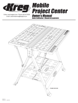
Exploded View
10
37
20
38
36

Nylonsetscrews 2
VACUUMPORT NK8309 1
48CENTER-READINGTAPE RT10140 1
FENCEFACES NK9206 2
HARDWARE PACK #4 NK8350 1
¼-20x1½atheadbolts 4
¼brassatwashers 4
T-knobs 4
BITGUARD RT10133 1
HARDWARE PACK #5 NK8353 1
¼-20x1¼ T-bolts 2
Spacers 2
¼brassatwashers 2
T-knobs 2
JOINTINGRODS RT10131 2
HARDWARE PACK #6 NK8361 1
¼-20x1¾ T-slot bolt 1
Micro-adjuster base 1
1
⁄4brassatwasher 1
T-knob 1
Micro-adjuster dial 1
1
Hardware for this section is in HARDWARE PACK #1.
To mount the fence to the Kreg Precision Router Table PRS1025,
raise the handle (1) to release the clamp-block assembly (Parts 1-7)
from the mounting rail (8). Position the rail on the bottom of the table top
at the right rear corner, aligning the holes in the rail with the holes in the
table top. Fasten the rail with the screws (9).
Attach the mounting rail
2
This router-table fence is designed to be mounted on the Kreg
Precision Router Table Top PRS1025, which is 1
1
16
thickness between the mounting rail (8) and the router table top to
1
16
the shim or rout the recess on the bottom of the router table top at
the rear right corner. Raise the handle (1) to release the clamp-block
assembly (Parts 1-7) from the mounting rail (8). Position the rail on the
bottom of the table top with the rear end of the rail and the rear edge of
and fasten the rail to the top with the screws (9).
1
Position the clamp block assembly on the mounting rail. Adjust the
nylon set screws (2) in the front of the clamp block (3) so they just
graze the mounting rail. The clamp block should move easily but not
wobble.
Install the clamp block
2
(11) into the clamp block slot. The rib centered
position. (See Indexing the fence under the section Using Your Router
Table Fence.)
Assembly
3
For table tops other than the Kreg Precision Router Table Top
PRS1025, drill and rout the keyhole slot for the ¼-turn fence lock.
The length of the slot should allow the face of the fence to be positioned
3
2
11
See
Step 3
at left
13
⁄32
1
⁄2
1 Diameter
30
3
⁄4
To right hand edge
10
8
9
bottom
rear-edge
Installing the clamp block tape
!
ATTENTION To mount this fence to the Kreg Precision Router
Table PRS1025, see Step 1. To mount the fence to other router tables,
see Steps 2 and 3.

Assembly
1
Hardware for this section is in HARDWARE PACK #2.
Place four spacers (13) over the mounting holes in the clamp block
(3). Fasten the extrusion (12) to the clamp block with washers (14) and
machine screws (15). Finger-tighten the screws.
Add the fence extrusion
2
Hardware for this section is in HARDWARE PACK #3.
Slip the machine screw (16) through the fence-lock handle (17) and
fence-lock base (18). Drop the handle/base/machine screw assembly
(12) and
faces the back of the fence and the handle points away from the back
of the fence. Slide the fence-lock anchor (19) onto the machine screw
Thread the lock nut (20) onto the machine screw. Make sure the nylon
insert in the lock nut faces down. Lower the fence-lock anchor onto the
lock nut, housing the nut in the tapered hexagonal recess in the anchor.
Use a screw driver to draw the lock nut into the fence-lock anchor. Once
the nut is fully seated in the anchor, it will not drop out.
3
Position the fence-lock handle (17) pointing away from the fence
and angled 45 degrees to the left [viewed from the back of the
fence]. This is the locked position for the handle. To adjust fence-lock
tension, tighten the machine screw with a screw driver until the clamp
is tight enough to hold the fence in place. Rotate the handle ¼-turn
counterclockwise to release the fence.
4
Thread two set screws (21)
handle. You’ll use these screws to square the fence. (See the
section Align and square the fence.)
15
12
14
21
13
3
12
19
18
17
16
!
ATTENTION When using the fence with a table top thinner than
1
1
16
out in the fence-lock base.
20
!
WARNING Periodically check the fence lock to make sure it has
not loosened with use. Tighten the machine screw (16) as needed.

Assembly
5
Insert the tabs at the bottom of the vacuum port (22) into the groove
in the base of the fence extrusion. Align the two interior pegs on the
dust port with the inside edges of the router-bit cutout. Push down on the
spring-lock tabs at the top of the port and snap them into the groove in
the back of the extrusion.
6
Mark the center of the top edge of the fence extrusion. Position the
zero mark of the self-adhesive tape (23) at the mark and remove
the protective backing as you adhere the tape to the extrusion. Trim the
7
Hardware for this section is in HARDWARE PACK #4.
Install the fence faces (24)(25) inserted through
washers (26) and T-knobs (27).
26
25
27
24
23
22

Assembly
8
Hardware for this section is in HARDWARE PACK #5.
Assemble the bit guard (28) with T-bolts (29), spacers (30), brass
(31), and T-knobs (32). Slide the T-bolt heads into the T-slot
at the top front edge of the fence extrusion, center the guard on the
router-bit cutout, and tighten the knobs.
Align and square the fence
9
To store the jointing rods (33), slide them into the round channel at
Jointing
under the section Using Your Router Table Fence.)
1
Using a combination square as a gauge, align the fence parallel to
the miter-gauge slot. Lock the clamp block and tighten the ¼-turn
fence lock. Re-check the parallel alignment and then tighten the hex-
head machine screws that secure the fence extrusion to the clamp block
assembly. Release the fence, slide it back and forth on the mounting rail,
and lock it in place. Verify the parallel adjustment.
30
31
33
28
29
32

Assembly
2
Industry standards allow a slight amount of end-to-end twist in
aluminum extrusions. To eliminate any twist, secure the fence with
the clamp block and ¼-turn fence lock. Place a square against the fence
face at the left end of the fence. Use the set screws (21)
¼-turn handle to align the fence face with the square.
2
Slide the head of the T-slot bolt into the mounting rail slot from
the front end and tighten the knob. The micro-adjuster can be
stored at the front of the mounting rail without interfering with router-
table operation. (See Micro-Adjustment under the section Using Your
Router Table Fence.)
1
Hardware for this section is in HARDWARE PACK #6.
Slide the T-slot bolt (34) through the base (35) and the washer (36).
Thread on the T-knob (37). Insert this assembly into the dial (38).
Install the micro-adjuster
2121
34
38
35
37
36

a) Read, understand, and follow your router manufacturer’s safety warnings
and instructions.
b) Disconnecttherouterfrompowerbeforemakingadjustments.Neveradjust
the fence, plate, reducing rings, or any part of the router or router table while the
router is running.
c) Placetheroutertableonaatsurfacetopreventtippingorsliding.Never
stand on the router table.
d) Donotattempttoroutwarped,twisted,orbowedworkpieces.All
workpiecesmusthaveatfacesandsquareedges.
e) Donotattempttoroutverylargeworkpiecesonaroutertable. Very large
workpiecescanbedifculttocontrolandcancausetheroutertabletotipover.
f) Onlyuserouterbitsinyourrouter.Neverusetoolssuchascarvingburrs,
mounted abrasives, wire wheels, or drill pits, even if the shanks match the
diameter of the router collet.
g) Weargloveswhenhandlingrouterbits. Cutting edges are sharp.
h) Neverusedirty,dull,ordamagedrouterbits. Remove wood-resin build-up
withacleanerspecicallyformulatedforcuttingtools.Havedullbitssharpenedby
aqualiedperson.Discarddamagedbits.
i) Makesureatleast75%oftherouter-bitshanklengthissecurelyheldinthe
router collet. To ensure a secure hold, leave
1
⁄16” to
1
⁄8” (2mm-3mm) between
the end of the bit shanks and the bottom of the collet.
j) Usetheinsert-platereducingringwiththesmallestopeningthatallowsthe
bittopassthroughit. A large gap around the bit can allow the workpiece to tip
into the bit and kick back.
k) Positionthefencefacesascloseaspossibletothebit. Turn the bit by
hand to check for interference. Firmly tighten the fence-face T-knobs before
routing.
l) Adjustrouterspeedtomatchthediameterofthebit. Reduce router speed
when using large-diameter bits. See Table2 for recommended router speeds.
m) Makesuretheroutermotorissecurelyclampedinthebasebefore
starting the router.
n) Always support the workpiece with the fence or start pin. Only use the
starter in with router bits that have a guide bearing.
o) Whenusingthefence,alwayspositionthebitguardovertherouterbit
andasclosetotheworkpiecesurfaceaspossible.
p) Neverremovealargequantityofstockinonecut.Make several
progressively deeper cuts, adjusting the router bit or fence position between cuts.
q)Keephandsawayfromtherotatingbitandyourbodyoutofthepathof
the cut. Always use the bit guard, Use push sticks, push blocks, and feather
boards whenever possible, especially when routing narrow workpieces. Turn off
the router before clearing parts of scrap.
r) Avoid awkward hand positions, where a sudden slip could cause contact
withtherotatingbit.Neveroverreach.
s) Avoid routing small parts.Routtheproleonalargeworkpieceandthencut
theparttonalsizefromthelargeworkpiece.Ifyoumustroutasmallpart,build
an appropriate jig or hold the part with a wood handscrew clamp.
t) Makesuretheworkpieceisclearofthebitandthebitcomestoa
completestopbeforeadjustingtheworkpieceposition.Neverstarttherouter
with the workpiece in contact with the bit.
u) Avoidkickbacks.Kickbacksoccurwhentheworkpiecebindsorliftsoff
thetablewhilebeingrouted,causingittobethrownbacktowardthe
operator. To avoid kickbacks and potential injury, use sharp bits, keep the
machine aligned and maintained properly, and adequately support the workpiece.
Do not attempt to rout workpieces that are twisted, warped, or bowed, or that
have loose knots.
v) Feedtheworkpieceagainst(notwith)thebitrotation. The bit can grab a
workpiece fed with the rotation of the bit, violently eject it from the router table,
and can cause your hand to contact the bit.
w) Nevertrapaworkpiecebetweenthebitandthefence. When forming a
proleonthestraightedgeofaworkpiece,alwaysroutwiththebithousedinthe
fence and the edge of the workpiece against the fence.
x) Wheneverroutingaproleinwhichmaterialisnotbeingremovedbelow
aprotrudingportionofthebit,orapartoftheproleistrappedbetween
cuttersaboveandbelow,takeextraprecautionstopreventtheworkpiece
fromliftingoffthetablesurfaceduringrouting.A workpiece lifting off the table
cankickbackandcauseseriouspersonalinjury.Whenroutingtheseproles,itis
especiallyimportanttousestraight,atstockandavoidwarped,bowed,ortwisted
stock.
y) Periodically check the tightness of fasteners and adjustment and locking
knobsandthealignmentofthefence.Loose fasteners and knobs and a
misaligned fence can cause personal injury.
z) Thisroutertablefenceisdesignedforaspecicapplication.Donot
modify and or use it for any other application. If you have questions relative to
theapplicationoftheroutertable,DONOTuseituntilyouhavecontactedKreg
Tool Company and have been advised accordingly.
Guidelines for extension cord use
Extension cords are only to be used for temporary purposes. They do not replace the
need for installation of outlets and proper wiring where necessary.
In the shop and on construction sites:
1. Extension cords with an equipment grounding conductor must be used at all
times.
2. Extension cords must be protected from damage, and not run through doorways
or windows where the doors or windows can close, causing damage to the cord.
3. Extension cords must be a minimum of 16 AWG and be rated for the equipment
in use.
4. Extension cords must be periodically inspected to ensure that the insulation and
conductivity of the wires are not compromised.
5. Extension cords should not be run through water or allowed to have connections
that may be exposed to accumulated water.
Always follow bit manufacturer’s speed recommendations. Some bit designs require
speeds for safety or performance.
Nameplate
Amperes
@120 V
Extension Cord Length
25’ 50’ 75' 100' 150' 200'
Recommended Wire Gauge
0 -5 16 16 16 14 12 12
5.1 - 8 16 16 14 12 10 NR
8.1 -12 14 14 12 10 NR NR
12.1 - 16 12 12 NR NR NR NR
NR–NotRecommended
TABLE 1
TABLE 2
Recommended Router Bit Speeds
Bit Diameter Maximum Speed (RPM)
24,000
18,000
16,000
12,000
Safety Instructions specic to using a Router Table tted with the Precision Router Table Fence
WARNING:
!
This product can expose you to chemicals including Acrylonitrile
and other chemicals, which are known to the State of California to cause cancer and
reproductive harm. For more information go to www.P65Warnings.ca.gov.
WARNING:
!
Drilling, sawing, sanding or machining wood products can expose
you to wood dust, a substance known to the State of California to cause cancer. Avoid
inhaling wood dust or use a dust mask or other safeguards for personal protection.
For more information go to www.P65Warnings.ca.gov/wood.

Using Your Router Table Fence
Indexing the fence
(A) and clamp block lens cursor (B) provide an easy
way to index the fence to a router bit, allowing you to accurately rout
perform a two-step routing task and return the fence to the initial position.
General Routing
(A) Use the insert-plate reducing ring with the smallest opening that
allows the bit to pass through it. (B) Position the fence faces as close as
possible to the bit. Turn the bit by hand to check for interference. Firmly
tighten the fence-face T-knobs before routing. (C) Position the bit guard
over the router bit and as close to the workpiece surface as possible. (D)
Feed the workpiece against (not with) the (E) the bit rotation.
Micro-Adjustment
Start with the fence locked in position. Slide the adjuster against the
end of the clamp block, turning the dial so the zero mark aligns with the
bottom edge of the clamp block. Tighten the knob. When adjusting the
fence away from the micro-adjuster, release the fence and turn the dial
to the desired increment. The dial pushes the fence to the new position.
Lock the fence. When adjusting the fence toward the micro-adjuster, turn
the dial to the desired increment and tighten the knob. Unlock the fence,
push it against the micro-adjuster, and re-lock the fence.
Jointing
Remove the jointing rods (33) stored in the fence extrusion. Loosen the
outfeed fence face knobs. There are two shallow and two deep round
channels in the fence extrusion behind the fence faces. For a
1
16
slide the rods into the shallow recesses. For a
1
32
into the deep recesses. With the rods in place, tighten the outfeed fence-
face knobs.
A
E
B
C
D
A
B

Using Your Router Table Fence
Use a scrap piece of wood to test the setup. If you feed the scrap past
the bit and it runs into the leading end of the outfeed fence face, the
fence is too far forward and you’re not removing enough material. Use
the micro-adjuster to move the fence back.
If the bit gouges the scrap at the trailing edge, the fence is too far back,
and you’re removing too much material. Use the micro-adjuster to move
the fence forward.
Move fence back
Workpiece
hits outfeed
fence face
Move fence forward
Starting Pin
To use the starting pin, begin with your workpiece touching the pin, but
not in contact with the router bit. Slowly pivot the workpiece into the bit
until the workpiece makes contact with the bit guide bearing. Always
feed the workpiece so the router bit rotates against (not with) the feed
direction. With the workpiece in solid contact with the guide bearing,
ease the workpiece off of the starting pin and feed the workpice along
the guide bearing.
T-Slots
The fence extrusion features two T-slots, one on the top and one on the
front face. Use T-bolts to attach feather boards and stops.
Center-Reading Tape Rule
Center the fence on the router bit and use the tape rule to position stops
for routing stopped cuts.
!
WARNING Use the starting pin when routing along curved edges
and only with router bits that have a guide bearing. When routing along
straight edges, always use the fence.
Install a straight bit in the router. Place a steel ruler against the outfeed
fence face and position the fence so the bit just grazes the ruler.

For assistance with any Kreg product, contact us through our Web site or call Customer Service.
Si vous avez besoin d’aide concernant les articles Kreg, communiquez avec nous sur notre site Web ou appelez notre service à la clientèle.
Si requiere asistencia con cualquier producto Kreg, póngase en contacto con nosotros a través del sitio web o llame al Servicio al Cliente.
www.kregtool.com • 800.447.8638
/