Page is loading ...

CRAFTSMAN
ROUTER

-1-
CRT MK2
Contents
Items Enclosed _______________________2
Description of Parts ___________________2
Safety Precautions
- Cutter Care _________________________3
- Useful Advice ________________________3
Assembly _________________________4-13
- Identification of Router Mounting Holes ____6
- Fitting router to fixing plates ___________6-7
CRT/Mk2 Fixing Plates _______________8-9
Adjustment
- Fence Adjustments ___________________14
- Workpiece Support ___________________14
- Cutting Depth/Cutting Height ___________14
Optional Accessories ______________15-19
Operation
- Edge Moulding with the Back Fence _____20
- Grooving with the Back Fence __________21
- Full Edge Moulding ___________________21
- Across the grain routing with Mitre Fence _22
- Stopped Moulding ____________________22
- Tenon Cutting _______________________23
- Routing without a Back fence ___________24
- Mounting a Lead-On Pin_______________24
- Profile Working Procedure___________24-25
Producing a Shield ________________26-27
Spare Parts
- Spare Parts List ___________________28-30
- Spare Parts Diagram _______________31-34
Maintenance and Cleaning_____________35
Please read the operating instructions
carefully and keep them together with
your router table.
If you require further technical information or spare parts for this router table,
please call our technical support department on 01923 224681 or your agent.
☎
The following symbols are used throughout this
manual:
IMPORTANT!
Denotes possible risk of personal injury, or
damage to the tool in case of non-
observance of the instructions in this
manual.
1030mm
359mm
367mm
605mm
Specification
Working height with floor stand accessory
- 1000mm
Back fence height
- 100mm
Back fence extraction point diameter
- 58mm
Table top aperture diameter
- 57mm
Push block max. tenon thickness - 110mm
Weight (without accessories)
approximately 10kg
Intended use
The unit is intended for stationary operation of
routers.
Please remember to return your
guarantee card within 14 days of
purchase.

1
23
4
5
6
7
8
9
10
12
13
11
12
-2-
CRT MK2
DESCRIPTION OF PARTS
1 Legs
2 Fixing plate
3 Table top
4 Back fence
5 Workpiece support
6 Guard
7 Tenon push block
8 Lead-on pin
9 Mitre fence
10 Switch
11 Pushstick
12 Table extensions
13 Insert rings
ITEMS ENCLOSED
1 x Table top
4 x Legs
1 x Back fence and fittings
1 x Workpiece Support and fittings
1 x Tenon Block and fittings
1 x Top guard and fittings
1 x Mitre fence
1 x No-Volt Release Switch
3 x Insert rings
2 x Table extensions
1 x Lead-on Pin
1 x Spanner (9.5mm A/F)
1 x Screw and Fittings Pack
1 x Pushstick
1 x Instructions
1 x Guarantee card

-3-
CRT MK2
SAFETY PRECAUTIONS
■ Always switch off the power and unplug the
router when changing cutters or when making
adjustments.
■ Always wear protective goggles when routing.
■ Wear sound protective ear muffs when routing
for long periods of time.
■ Always wear a dust mask. Use dust extraction
equipment whenever possible.
■ Do not wear loose clothing. Make sure baggy
sleeves are rolled up and ties are removed.
■ Always remove spanners and hex keys from
the workpiece before switching router on.
■ Keep hands well clear of the router cutter
when routing.
■ Avoid accidental starting of the router. Make
sure the power switch is in the ‘Off’ position
before plugging in and connecting to the
electrical supply.
■ Never leave the router unattended when
running. Always wait until the router comes to
a complete stop before making adjustments.
■ Do not switch the router on with the cutter
touching the workpiece.
■ Mount the router table securely to a work
bench.
■ Periodically check all nuts and bolts to make
sure they are tight and secure.
Cutter Care
■ Do not drop cutters or knock them against
hard objects.
■ Cutters should be kept clean. Resin build-up
should be removed at regular intervals with
Resin Cleaner
®
. The use of a dry lubricant will
act as a preventative such as Trendicote
®
PTFE spray. Do not use PTFE spray on
plastic components.
■ Cutter shanks should be inserted into the
collet at least 3/4 of shank length to prevent
distortion. A distorted collet should be
discarded, as it can cause vibration and
damage the shank.
■ Do not over-tighten collet as this will score the
shank and create a weakness there.
■ It is also advisable to periodically check the
router collet nut for wear.
Useful Advice
■ Judge your feed rate by the sound of the
motor. In time, the operator will acquire a ‘feel’
for the router, and a feed speed relative to the
work will come naturally. Too slow a feed will
result in burning.
■ Apply the normal precautions as with any
electric power tool.
■ The main abuse of routing machines is the
inclination for operators to overload them. The
motto is ‘Keep the revs up’. The drop in
revolutions should not exceed, if possible,
more than 20% of full running speed.
■ The motor of a router is susceptible to the
accumulation of sawdust and wood chips, and
should be blown out, or ‘vacuumed’,
frequently to prevent interference with normal
motor ventilation.
■ Refer to the Instruction Manual supplied with
your router for full details of it’s features and
safety information.
■ Trial cuts should be made on waste material
before starting any project.
■ Do not store the router on the floor, as
chippings, pins or dirt can drop into the air
intake of the router.
IMPORTANT:
To move table with leg stand
fitted, please lift. Do not drag.

-4-
CRT MK2
ASSEMBLY
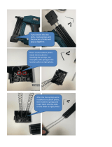
Assemble the parts as show in A to N.
For identification all fixings are
illustrated as actual size.
x16
x16
x18
A
B
ACTUAL SIZE
x18

-5-
CRT MK2
x2 x2
x2
x2
C
D
E
x2
PLEASE NOTE
Nut is fitted reversed
x1
x1
x1
x2

Special note for Bosch POF routers
For the Bosch POF range of DIY routers a
packing piece must be made in 3mm to 6mm
thick plywood or MDF. This is then placed
between the underside of the plate in the table
and the underside of the router base. The
fixing screws can then be used. Enlarging the
aperture in the base of the router is also
advised if large diameter tooling is to be used.
-6-
CRT MK2
Identification of Router Mounting
Holes and Screws (see pages 8 & 9).
■ Identify the mounting holes and fixing screws
(including washers & nuts if router base
requires re-drilling) which will be required to
suit your router.
■ Identify whether your router or the fixing plate
requires re-drilling.
■ Bolt the router onto the fixing plate first with
the operating controls to the front, before
fitting to the table.
■ The fixing plate is symmetrical therefore once
the router is mounted to it, it can be fitted to
the router table in four different positions. The
orientation of the plate depends on which
router is fitted. It is advisable to position the
plate so that controls for speed or height are
easily accessible.
IMPORTANT!
Some routers may require the
removal of the plastic base
slider to allow fitting to plate.
IMPORTANT!
Carry out the following re-
drilling only if required.
Re-drilling Router Base Only
■ Invert and stand your router onto a suitable
surface.
■ Place the fixing plate facing upwards onto
the base of your router.
■ Identify holes 1 and 2, or holes 3 on fixing
plate (Ref. CRT/FP/A see page 8).
■ Fit a large diameter cutter (max. 53mm Ø)
into your router and tighten collet.
■ Retract plunge mechanism and lock off
allowing cutter to protrude through the base.
■ Adjust position of the fixing plate to
centralise the cutter within the centre hole.
Take care not to damage cutter or to touch
sharp edges.
■ Ensure that the holes you are about to drill in
the base do not interfere with any of the
features on the router or any webbings in the
casting of the router base. A slight turning of
the plate may be required to miss such
obstructions.
■ Mark the centre of the holes onto the base.
■ Remove plate and mark the centre of the
holes with a centre punch.
■ Drill a hole at these points with a 6mm
diameter drill bit.
■ Clean up edges of holes if required.
Re-drilling Fixing Plate Only
■ Remove the plastic base of the router.
Alternatively a photocopy or an outline of the
base can be made of the plastic base
instead.
■ Draw cross lines onto the plastic base of the
router.
■ Draw cross lines on the fixing plate with a
pencil. These cross lines should bisect the
plate on both sides.
Packing
piece

-7-
CRT MK2
■ Align the lines on the fixing plate with those
on the plastic base and secure the fixing
plate to the plastic base.
■ Using a centre punch, mark the centres of
holes.
■ Drill the required hole size with a suitable
metal cutting drill bit. Best results will be
obtained if your power drill is mounted in a
drill stand.
■ Countersink the hole with a countersink bit
to a depth so the heads of the screws are
slightly below the top surface. Clean off any
burrs created.
IMPORTANT!
If you do not have the
necessary equipment to carry
out these operations, then a
local engineering shop will be
able to carry them out
accurately for you.
Re-drilling both Fixing Plate and
Router Base
■ Invert the router and lay the
fixing plate onto the upturned base.
■ Clamp the fixing plate and router base
together with two cramps.
■ Ensuring that the drill bit will not foul any
webbing or fixtures on the router base, drill
with a 6mm diameter metal cutting drill bit
into the fixing plate and through the router
base two holes approximately 75mm apart.
■ Unclamp the router base and fixing plate.
■ Countersink the fixing plate holes with a
countersink bit to a depth so the screw heads
are slightly below the top surface. Clean off
any burrs created on both the fixing plate and
router base.
CL
CL

-8-
CRT MK2
44
4
3
3
11
5
5
5
5
2
8
8
66
6
77
7
TREND T5 1 E x 2
TREND T9 1 & 2 E x 3
AEG OF4505, OF500S, OFE710 3 ● G x 2
ATLAS COPCO OFS720, OFSE850, OFS50
OFSE1000, OF500S 3 ● G x 2
B&D KW779, 780(E), 800(E)
BD780(E) 4 A x 3
B&D SR100, DN67, BD66 3 ● G x 2
BOSCH POF400, 500A, 600ACE 3 F x 2
BOSCH GOF1600A, 1700ACE 1 & 2 F x 3
DEWALT DW613 1 E x 2
DEWALT DW620, 621 1 E x 2
DEWALT DW625EK 1 & 2 F x 3
EINHELL EOF850SP 3 ● G x 2
ELU MOF96(E) MK1 3 ● G x 2
ELU MOF96(E) MK2 1 E x 2
ELU OF97(E) 1 E x 2
ELU MOF131, 177(E) 1 & 2 F x 3
FELISATTI R346EC 1 & 2 F x 3
FELISATTI TP246(E) ■● G x 2
FERM FBF-6E, FBF-8E 3 ● G x 2
FESTO OF900(E), 1000(E),
1010EBC, 2000(E) 1 & 2 ● H x 3
HITACHI M8(V) 5 B x 4
HITACHI FM8, ZK2008 3 ● H x 2
HOLZHER 2335, 2355, 2356 ■● G x 2
KANGO R8550S 3 ● G x 2
KINZO 250C44 ■ F x 2
KRESS FM6955 3 ● G x 2
LYNX RT-800-A 3 ● G x 2
MAFELL LO50E, 65E 1 & 2 ● H x 3
MAKITA RP0910, 1110C 1 E x 2
METABO OF528 3 ● G x 2
METABO OF1028, OFE1229 ■● G x 2
METABO OF1612, OFE1812 ■● G x 2
NUTOOL NPT850 3 ● G x 2
PERLES OF808(E) pre 1999 3 ● G x 2
PERLES OF808(E) post 1999 1 E x 2
PERFORMANCE POWER 1020W 3 ● G x 2
POWER DEVIL PDW5026 3 ● G x 2
ORTER CABLE 100, 690, 693 3 ● H x 2
POWER DEVIL PDW5027 3 ● G x 2
RYOBI R500, R502 1 & 2 ● H x 3
SPARKY X52E 3 ● G x 2
STAYER PR50 3 ● G x 2
VIRUTEX FR77C, 78C, 66F 3 ● H x 2
WADKIN R500 1 & 2 ● H x 3
WICKES 900W 3 ● G x 2
BOSCH GOF900A, 900ACE, POF800ACE 6 H x 3
BOSCH GOF1300ACE 7 H x 3
RYOBI RE600N, R600N,RE601,R601 8 I x 2
CRT/FP/A
CRT/FP/B
● Re-drilling of router base by user required
■ Re-drilling of insert plate by user required
* Requires 3mm packing piece
CRT/MK2
FIXING
PLATES
C
UNF10-32
x3/8"
B
M5x10mm
A
M4x12mm
IMPORTANT!
Some routers may require the
removal of their plastic base
slider to allow fitting to the plate.
*
**

-9-
CRT MK2
11
11
9
9
10
10
11
11
13
13
13
12
12
12
13
14
14
MAKITA 3620 10 D x 2
MAKITA 3612(C) 9 D x 2
11 A x 4
MAKITA 3612BR 10 D x 2
11 A x 4
MAKITA 3600B ■ D x 2
■ A x 4
CRT/FP/C CRT/FP/D
G
M6x25mm
F
M6x12mm
E
M6x10mm
I
M8x20mm
H
M6x35mm
D
M5x16mm
ATLAS COPCO OFSE2000 12 F x 3
CASALS FT750, 1000E, FT2000VCE 12 F x 3
DRAPER R1900V 12 F x 3
FREUD FT1000E, FT2000E 12 F x 3
HITACHI M12SA, M12V 13 B x 4
HITACHI TR12 ■ B x 4
RYOBI RE120, R150, R151, RE155K 14 D x 2
PEUGEOT DF55E, DEF570E 14 B x 2
SKIL 1835, 1875U1 ■ C x 3

-10-
CRT MK2
x4
x1
The fixing plate must be fitted to the router
base before installation into the router
table.
F
G
x1
Mounting Table to Workbench or
Workboard
The router table must be mounted onto either
the optional floor stand or onto a suitable
workbench or workboard.
Each table leg has four holes at the bottom
mounting. Firmly secure the table assembly to a
workbench or workboard, using self-tapping
screws (not provided).
If a workboard is used, this will allow quick
mounting and removal from a workbench by
using cramps. If a Workmate
®
is to be used
then a batten can be fitted to allow securing in
the Workmate’s
®
jaws.
Workboard 575mm x 450mm
Batten 560mm x 100mm
IMPORTANT:
Please tighten
screws across
the diagonals,
to ensure the
plate remains
flat. Tighten all
screws evenly.

-11-
CRT MK2
x1
x1
x1
x1
x1
x1
x1
x1
x2
x4
x2
J
K
L

-12-
CRT MK2
Mounting the No-Volt Release Switch
■ The no-volt release switch serves as start-up
protection. When the router is plugged in and
its on/off switch depressed, the router starts
only after the green switch is pressed.
■ Switch off the router using the red button.
■ Attach the no-volt release switch to the table
leg with the screws provided.
■ Plug the router into the socket.
IMPORTANT:
Always remove the plug of the
No-Volt Release Switch from the
power source before making any
adjustments.
Ø
Ø
Insert Rings
■ For router cutter diameters up to 50mm,
insert rings can be fitted. They serve to keep
the opening between the tool and the routing
table as small as possible.
■ The diameter of the insert ring should be
approximately 4mm larger than the cutter
diameter.
Max. router cutter
size without insert
rings:
- 53mm Ø max
Max. router cutter
sizes with insert
rings:
32mm
= 28mm Ø max.
48mm
= 44mm Ø max.
54mm
= 50mm Ø max.
Ø
M

-13-
CRT MK2
Guard Operation
When routing with the top guard, never reach
under the guard or swing the guard away. The
guard should not be removed from the back
fence and should always be used in the lowered
position.
Cutter Rotation
Feed Direction
Feed Direction
■ Always work with constant, medium rate.
Feeding too slow will results in burn marks
and excessive heat build up of the cutter.
■ Good results will be obtained by removing
small amounts of material in several passes.
■ Always feed work in the opposite direction to
the direction of rotation of the router cutter.

-14-
CRT MK2
ADJUSTMENT
Fence Adjustments
To make adjustment to the lateral movement of
the back fence:
■ Release the back fence knob.
■ Loosen the two screws that secure
the adjustable wedge.
■ Adjust position and re-tighten screws.
■ Re-tighten the back fence knob.
The back fence can be adjusted forwards and
backwards, using the graduated scales to gauge
the depth of mould.
For edge moulding, position the back fence with
the fastening bolts towards the front of the slot.
For panel grooving (i.e. routing of grooves away
from the edge of the workpiece) the fastening
bolts should be to the rear of the holes and slots.
Workpiece Support
The workpiece support provides safe guiding of
the workpiece when routing the complete edge
of the surface.
Adjustment range from:
0 to 12.7mm (1/2”)
Cutting Depth/Cutting Height
Before starting to work:
■ Adjust the cutting depth (A) by adjusting the
position of the back fence.
■ Adjust the cutting height (B) by raising or
lowering the cutter using a fine height
adjuster (if fitted). Alternatively rapid height
adjustment can be made if a PlungeBar is
fitted.
max.
58mm
32mm

-15-
CRT MK2
OPTIONAL ACCESSORIES
Hose and Connector - CRT/3 & CRT/4
The back fence is provided with an extraction
point for connection to suitable vacuum
extractors. The internal hole diameter is 58mm
(2 1/4"). Suitable fittings with 58mm outside
diameter are available for most extractor units.
■ Only a vacuum extractor unit recommended
for use in the workshop should be used.
■ A suitable adaptor and extraction hose can
be purchased as optional accessories.
The hose (Ref. CRT/4) has an outside diameter
of 39mm and inside diameter of 32mm. The
hose adaptor (Ref. CRT/3) is a three piece
design that allows the hose to swivel freely.
■ Assemble the hose adaptor onto the end of
the hose as shown and insert into back
fence.
■ Fit the other end of the extraction hose to
your dust extractor.
39mm
x 3metre
Large capacity extraction hose - T30/22
A larger 58mm diameter hose 1.5 metres long
with integral connector is available (Ref. T30/22)
for fitting to the CRT and the Trend T30A vacuum
extractor. This hose will provide an increased rate
of air flow to improve extraction effectiveness.
■ The hose is simply inserted into the back fence
extraction point.
58mm x 1.5metre
T30/22
CRT/3
CRT/4

-16-
CRT MK2
Profiling Top Guard - CRT/2
■ Remove the back fence and assemble the
profiling top guard as shown.
The use of the optional profiling top guard is
recommended when profiling of workpieces
workpieces with a pin or ball bearing guided
cutter. It will prevent the operator's fingers
inadvertently contacting the cutter while
providing good visibility.
Pages 26 and 27 describe a typical application
involving using ball bearing guided cutters with
to make a shield.
Spring Pressure Clamps - CRT/10
The optional spring pressure clamps can be
mounted to the back fence. When adjusted to
suit the width and thickness of the workpiece,
they ensure the workpiece is held down onto
the surface to obtain accurate machining of
the workpiece.
■ Remove back fence from table surface
and assemble as shown.
Adjustment
■ The spring pressure clamps will require
adjusting to suit the height and width of
workpiece being routed.
■ The pressure strips should provide enough
pressure to prevent the workpiece lifting
from the table surface, but not too much
as to create friction which would prevent
the workpiece from sliding freely.
■ The horizontal bar with pressure strip fitted
can be removed from the vertical pillars
when not required. The vertical pillars can
be left in position and will not impede the
tenon push bock system.
CRT/10
CRT/2

-17-
CRT MK2
Vertical Routing Support - CRT/5
For safe routing of narrow panels a vertical
routing support is available.
■ Assemble the support as shown.
■ Adjust the depth of cut and router cutter
height making sure the router is unplugged
when making these adjustments.
■ The vertical routing support should be
positioned to guide the workpiece but allow it
to slide freely.
■ It is important to check that the entire length
of the workpiece will travel between the fence
and the support without binding. This is done
simply by holding the workpiece up to clear
the router cutter and passing it through the
cutting area to ensure no binding occurs.
■ Once the vertical routing support is
positioned correctly lock it into place securely
by tightening both knobs so that the vertical
routing support will not move.
IMPORTANT:
Do not overtighten the knobs as
this may result in damage.
CRT/5

-18-
CRT MK2
x4
x44
x44
To adjust for
uneven floors,
loosen screws,
raise or lower
foot and re-
tighten.
Floor Stand - CRT/FS
Always mount the routing table on a
work table, bench or on the optional
floor stand.
IMPORTANT:
Please do not fit top screws
until CRT/MK2 is fitted to
the floor stand. Once
CRT/MK2 is placed onto
floor stand, the screws can
be fitted.
IMPORTANT:
Do not drag unit along floor. Please lift to move.

-19-
CRT MK2
Enclosure Kit - CRT/EK
x32
x32
x1
x1
x1
+
-
/