Page is loading ...

Band Saw Fence
Precision
OWNER’S MANUAL
Item# KMS7200
Tools Required:
•
7
⁄16" or 10mm wrench
• Electric drill,
11
⁄32" drill bit, le (if necessary)
• Combination square (optional)
•
1
⁄2" wrench
• Phillips screwdriver
•
5
⁄32" and
3
⁄16" hex wrenches
www.kregtool.com • 800.447.8638
FT4177
Version 4 - 01/2018

Table of Contents
1.
Read all instructions and safety warnings before using this tool.
SAFETY 2
PARTS DIAGRAM 3
CHECK THE RAIL SLOTS AND MOUNTING BOLTS 4
DRILL THE MOUNTING RAIL (When Necessary) 4
INSTALL THE MOUNTING RAIL 5
ASSEMBLE THE CLAMP BLOCK 6
ATTACH THE FENCE EXTRUSION 6
ADHERE THE MEASURING TAPE 7
PARALLEL ADJUSTMENT 7
BLADE DRIFT ADJUSTMENT 8
FEATURES 9
ACCESSORIES 10
WARRANTY 11

Safety Guidelines
2.
!
General Safety Rules
WARNING! To reduce the risk of injury, user must read the instruction manual.
WARNING! Read all instructions. Failure to follow all instructions listed below may result in electric shock, re and/or serious injury. The term
“power tool” in all of the warnings listed below refers to your mains-operated (corded) power tool or battery-operated (cordless) power tool.
SAVE THESE INSTRUCTIONS
1) Work area safety
a) Keep work area clean and well lit. Cluttered or dark areas invite accidents.
b) Do not operate power tools in explosive atmospheres, such as in the presence of ammable liquids, gases or dust. Power tools create sparks which may ignite the dust or fumes.
c) Keep children and bystanders away while operating a power tool. Distractions can cause you to lose control.
2) Electrical safety
a) Power tool plugs must match the outlet. Never modify the plug in any way. Do not use any adapter plugs with earthed (grounded) power tools. Unmodied plugs and matching outlets
will reduce risk of electric shock.
b) Avoid body contact with earthed or grounded surfaces such as pipes, radiators, ranges and refrigerators. There is an increased risk of electric shock if your body is earthed or grounded.
c) Do not expose power tools to rain or wet conditions. Water entering a power tool will increase the risk of electric shock.
d) Do not abuse the cord. Never use the cord for carrying, pulling or unplugging the power tool. Keep cord away from heat, oil, sharp edges or moving parts. Damaged or
entangled cords increase the risk of electric shock.
e) When operating a power tool outdoors, use an extension cord suitable for outdoor use. Use of a cord suitable for outdoor use reduces the risk of electric shock.
3) Personal safety
a) Stay alert, watch what you are doing and use common sense when operating a power tool. Do not use a power tool while you are tired or under the inuence of drugs, alcohol or medication.
A moment of inattention while operating power tools may result in serious personal injury.
b) Do not allow familiarity gained from frequent use of a tool to replace safe work practices. A moment of carelessness is sufcient to cause severe injury.
c) Use safety equipment. Always wear eye protection. Safety equipment such as dust mask, non-skid safety shoes, hard hat, or hearing protection used for appropriate conditions
will reduce personal injuries.
d) Avoid accidental starting. Ensure the switch is in the off-position before plugging in. Carrying power tools with your nger on the switch or plugging in power tools that have the
switch on invites accidents.
e) Remove any adjusting key or wrench before turning the power tool on. A wrench or a key left attached to a rotating part of the power tool may result in personal injury.
f) Do not overreach. Keep proper footing and balance at all times. This enables better control of the power tool in unexpected situations.
g) Dress properly. Do not wear loose clothing or jewelry. Keep your hair, clothing and gloves away from moving parts. Loose clothes, jewelry or long hair can be caught in moving parts.
h) If devices are provided for the connection of dust extraction and collection facilities, ensure these are connected and properly used. Use of these devices can reduce
dust-related hazards.
4) Power tool use and care
a) Do not force the power tool. Use the correct power tool for your application. The correct power tool will do the job better and safer at the rate for which it was designed.
b) Do not use the power tool if the switch does not turn it on and off. Any power tool that cannot be controlled with the switch is dangerous and must be repaired.
c) Disconnect the plug from the power source and/or the battery pack from the power tool before making any adjustments, changing accessories, or storing power tools.
Such preventive safety measures reduce the risk of starting the power tool accidentally.
d) Store idle power tools out of the reach of children and do not allow persons unfamiliar with the power tool or these instructions to operate the power tool. Power tools are
dangerous in the hands of untrained users.
e) Maintain power tools. Check for misalignment or binding of moving parts, breakage of parts and any other condition that may affect power tool operation. If damaged,
have the power tool repaired before use. Many accidents are caused by poorly maintained power tools.
f) Keep all guards and safety devices in place, properly adjusted, and in good working order.
g) Keep cutting tools sharp and clean. Properly maintained cutting tools with sharp cutting edges are less likely to bind and are easier to control.
h) Use the power tool, accessories, bits, and blades in accordance with these instructions and in the manner intended for the particular type of power tool, taking into account the
working conditions and the work to be performed. Use of the power tool for operations different from those intended could result in a hazardous situation.
i) Never stand on the tool. Serious injury could occur if the tool tips or if cutting edges are accidentally contacted.
j) Never leave a running tool unattended. Turn off the power and do not leave the tool until moving parts come to a complete stop.
5) Service
a) Have your power tool serviced by a qualied repair person using only identical replacement parts. This will ensure that the safety of the power tool is maintained.
6) Additional Safety Rules for the Precision Band Saw Fence
a) Read this manual and these safety guidelines. Follow the saw manufacturer’s safety guidelines. Learn the applications and limitations of the tool as well as the hazards
specic to it. Operating the tool before understanding safe and proper use could result in personal injury.
b) Ensure that the lock knob is tight and the fence extrusion T-knobs are secure prior to starting the band saw.
c) Keep hands away from the moving blade when operating the machine. Never reach behind the moving blade to clear debris.
d) Always support long boards on both the infeed and the outfeed end of the blade.
e) Always securely hold workpieces against the table and fence.
f) This fence system is designed for a specic application. Do not modify and/or use it for any other application. If you have questions about the band saw fence,
DO NOT use it until you contact Kreg Tool Company and receive advice.
!
WARNING:
!
This product can expose you to chemicals including
Acrylonitrile and other chemicals, which are known to the State of California
to cause cancer and reproductive harm. For more information go to
www.P65Warnings.ca.gov.
WARNING:
!
Drilling, sawing, sanding or machining wood products can
expose you to wood dust, a substance known to the State of California to cause
cancer. Avoid inhaling wood dust or use a dust mask or other safeguards for
personal protection. For more information go to www.P65Warnings.ca.gov/wood.

Assembly
3.
DK1313 2 T-knobs
DK1504 4
1
⁄4" brass washers
FT4025 2
1
⁄4"-20 x
3
⁄4" nylon socket head screws
FT4047 1 Right-to-left reading self-adhesive tape
FT4063 1 Lens cursor
FT4064 1 #10-32 x
1
⁄4" nylon screw
FT4136 1 Fence extrusion
FT4137 2
5
⁄16" brass washers
FT4138 2
1
⁄4"-20 x 2
1
⁄2" hex head bolts
FT4140 2 #10-32 x
3
⁄8" nylon set screws
FT4159 1 Mounting rail
FT4143 1 Clamp block
FT4144 1 Fence bracket
FT4185 2
1
⁄4"-28 x 1
1
⁄4" hex head bolts (Delta)
FT4146 2 M6-1 x 30mm hex head bolts
(Jet, Craftsman, Ridgid, and other imports)
FT4175 2
5
⁄16" x
3
⁄4" hex head bolts
FT4176 1 Lock knob
Part Number Quantity Description
DK1313
FT4047
FT4063
FT4136
FT4176
FT4159
FT4143
FT4144
FT4064
DK1504
FT4137
FT4138
FT4175
FT4025
FT4185 (Delta)
FT4146 (Jet, Craftsman, Ridgid, Import)
FT4140
DK1504
Band Saw Fence
Parts Diagram

Assembly
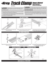
4.
For band saws with a left-hand table hole that does not align with
a left-hand slot in the mounting rail, mark the left-hand table hole
centerline on the saw table with a pencil. Mount the rail by inserting a
mounting bolt through the right-hand rail slot and threading it into the
right-hand saw-table hole. Snug, but do not tighten the bolt. Mark the
left-hand slot centerline on the rail.
Remove the mounting rail from the saw table and transfer the
centerline onto the back of the mounting rail. Mark hole centers on the
rail with a center punch. Drill overlapping
11
⁄32" holes and use a le to
nish forming the slot.
The positions of the slots in the mounting rail match the threaded holes in
the front edge of the tables of most band saws. The drawing shows slot
locations that match several popular brands. Other manufacturers use the
same locations. For brands not shown, align the right-hand mounting-rail
slot with the right-hand saw-table hole to see which left-hand rail slot aligns
with the left-hand table hole. If a left-hand slot does not align with the table
hole, see the section, Drill the Mounting Rail.
Two sets of mounting bolts are included with the Precision Band Saw
Fence:
1
⁄4"-28 x 1
1
⁄4" hex head bolts for some Delta saws and M6-1 x 30mm
hex head bolts for Jet, Craftsman, Ridgid, and others. You’ll need a 7/16"
wrench for the
1
⁄4"-28 bolts and a 10mm wrench for the M6-1 bolts. Test-t
the bolts in the saw-table holes to determine which ones to use.
Tip
The threaded mounting holes in your band saw table may contain debris
that make it difcult to drive the mounting bolts. To clear the debris,
thread-in and back-out the bolts several times, clearing loosened debris
with compressed air or a shop vacuum. If the bolts do not thread fully, you
may need to clean the threads with a tap. Consult your band-saw owner’s
manual or contact the saw manufacturer for the correct thread size.
Hold the left-hand end of the mounting rail in position
and transfer the saw-table hole centerline onto the rail.
Check the Rail Slots and Mounting Bolts
Drill the Mounting Rail (when necessary)
Disconnect the band saw from the power supply when installing the Precision Band Saw Fence.
Jet, Ridgid
Delta
Craftsman
top edge of mounting rail
remove area with le
11/32” hole
5/8" 1/8"

Assembly
5.
Slip a washer over one mounting bolt, insert the bolt through the right-
hand rail slot, and thread it into the right-hand saw-table hole. Snug, but
do not tighten the bolt. Slip a washer over the other bolt. Holding the rail
in position, insert the bolt into the appropriate rail slot and thread it into
the saw-table hole. Snug the bolt. Align the rail parallel to top surface of
the saw table and with the top edge of the rail
1
⁄16" below the bottom of
the miter-gauge slot. Tighten the bolts.
Tip
Set the blade of your combination square to the miter gauge slot depth
plus
1
⁄16". Then use the square to position the top edge of the mounting
rail at each mounting bolt.
Loosely fasten the rail at the right-hand end, then rotate
the rail into position and secure the left-hand end.
Install the Mounting Rail
1
⁄16"

Assembly
6.
Insert the T-shaped stem of the lens cursor into the clamp block, letting
the entire lens body protrude beyond the edge of the clamp block.
Secure the lens cursor with the #10-32 x
1
⁄4" nylon screw.
Thread two #10-32 x
3
⁄8" nylon set screws into the the rear corner
holes in the clamp block. Adjust the set screws to protrude
1
⁄16" below
the bottom surface of the block. These screws act as glides to provide
smooth fence movement.
Thread two
1
⁄4"-20 x
3
⁄4" nylon socket head screws into the front corner
holes in the clamp block until the ends of the screws are ush with the
bottom surface of the block.
Slip a
5
⁄16" brass washer on each of the
5
⁄16" x
3
⁄4" hex head bolts, insert
them through the fence bracket, and thread them into the clamp block.
Make sure the large hole in the fence bracket aligns with the rear hole
in the clamp block. Align the fence bracket square with the clamp block
and tighten both bolts.
Thread the lock knob into the front face of the clamp block until the
swivel pad protrudes
1
⁄16" beyond the inside surface. Position the clamp
block assembly on the mounting rail and lightly tighten the lock knob to
hold the assembly in place.
Assemble the Clamp Block
Insert the head of each
1
⁄4"-20 x 2
1
⁄2" hex head bolt into the T-slot in
the back of the fence extrusion. With one bolt in each U-shaped fence
bracket upright, position the fence extrusion against the bracket with
the bottom edge resting on the saw table. Slip a
1
⁄4" brass washer onto
each bolt and thread on a T-knob.
Test the operation of the Precision Band Saw Fence by sliding it from
side to side along the mounting rail.
Tip
To obtain smooth right-to-left fence movement, tighten the lock knob to
square the clamp block with the mounting rail. Then loosen the knob
just enough to allow the fence to slide.
Attach the Fence Extrusion
Lens cursor
Fence bracket
#10-32 x 1/4"
Nylon screw
#10-32 x 3/8"
Nylon set screw
Lock knob
1/4"-20 x 3/4"
Nylon socket
head screw
5/16" Brass washer
5/16 x 3/4" Hex head bolt
Clamp block
T-knob
Fence extrusion
Fence bracket
Lock knob
1/4" Brass washer
1/4" - 20 x 2-1/4"
Hex head bolt

Assembly
7.
Position the fence extrusion against, but not deecting, the blade and
tighten the lock knob. With a pencil, mark a line on the mounting rail in
front of and behind the red line on the lens cursor. Loosen the lock knob
and remove the fence from the mounting rail.
Peel the backing from the zero end of the self-adhesive measuring
tape, exposing about one inch of the adhesive. Align the tape zero mark
with the pencil lines on the mounting rail and press the tape into the
shallow groove in the rail. With the rst inch of tape adhered, pull the
remaining backing from under the tape, rmly pressing the tape into the
groove as you proceed.
Reinstall the fence assembly on the mounting rail and check the
position of the red cursor line against the zero mark on the measuring
tape. Re-zero the red line as necessary by loosening the screw that
holds the lens cursor in place, readjusting the cursor position, and
retightening the screw.
Tip
To make the measuring-tape backing easy to remove, fold the rst inch
of backing so it protrudes from the tape at an angle. With the rst inch
of tape adhered, pull the backing from under the tape, pressing the tape
into the mounting rail groove as you continue to remove the backing.
Adhere the Measuring Tape
Mark the position of the red cursor line on the mounting rail.
Align the measuring tape zero mark with the pencil
marks, peel away the backing, and adhere the tape.
To ensure that the face of the fence extrusion is parallel to the blade, rst
make sure your band saw table is perpendicular to the blade. See your
band saw owner’s manual for instructions on making this adjustment.
With the band saw table properly adjusted, position the fence assembly on
the mounting rail and lightly tighten the lock knob to hold the assembly in
place. Thread in the nylon screws at the front corners of the clamp block
until the tips contact the surface of the mounting rail. Check the alignment
of the face of the fence extrusion and the saw table with a square. To
adjust the alignment, loosen the lock knob and turn the right hand or left
hand screw to tilt the fence as needed. With the fence square to the saw
table, tighten the lock knob and adjust the nylon set screws at the back
corners of the clamp block so the tips contact the mounting rail.
Tip
Parallel adjustment is particularly important for cuts in which even a
small difference between the top and bottom of the cut will give poor
results, such as when cutting tenons, dovetails, and thin veneers.
Adjust either the left or right screw to align the face of
the fence extrusion perpendicular to the saw table.
Parallel Adjustment
Pencil marks

Assembly
8.
Sometimes when using the fence, a band saw will make a cut that does
not track parallel to the fence, either wedging the workpiece between
the fence and the blade or pulling the workpiece away from the fence.
This “drift angle” often is caused by a blade with teeth that are not set
evenly or that have become dull on one side.
To adjust your fence to compensate for the drift angle, remove the
fence assembly from your band saw and set it aside. Mark a line down
the center of a scrap board about 2" wide and 30" long. Cut on the line
to the middle of the scrap board. Hold the board rmly in place, shut off
the band saw and wait for the blade to come to a complete stop. The
angle at which you fed the board in order to keep the blade cutting on
the line is the drift angle. Use a pencil to trace a line onto the band saw
table along one edge of the board. Remove the board.
Remount the fence assembly on your band saw and loosen the bolts
that attach the fence bracket to the clamp block.
Align the fence with the pencil line on the table surface. Tighten the
lock knob, recheck the fence alignment, and tighten the fence bracket
bolts. Make a test cut to ensure that the workpiece tracks parallel to the
fence.
Tip
If you are not able to adjust the fence to the angle necessary to
compensate for blade drift, either your saw geometry is out of
adjustment or it is time to replace the blade. You can minimize the
amount of blade drift by adjusting the tracking and the tension on the
band saw. Refer to your band saw manufacturer’s instructions.
Blade Drift Adjustment
Loosen the fence bracket bolts to allow the fence
extrusion to pivot.
With the blade stopped, trace a line along the edge
of the board onto the saw table
The fence extrusion/fence bracket assembly pivots
for alignment with the blade drift angle.
Pencil line

Features
9.
•
The fence can be used on either side of the blade simply by switching
the fence extrusion from one side of the fence bracket to the other.
•
Position the fence extrusion anywhere along the fence bracket by
loosening the T-knobs and sliding the extrusion along the face of the
bracket. For example, to use the fence as a cutoff guide, position
the end of the extrusion slightly in front of the blade and feed the
workpiece with a miter gauge. The piece will be clear of the blade
when cut free and will not be caught between the blade and fence.
•
Switch the fence extrusion orientation from vertical to horizontal for
optimum upper blade guide support. Simply loosen the T-knobs, slide
the fence extrusion off the bolts, ip it over and slide the bolt heads
into the T-slot on the top of the extrusion.
With the blade close to the fence, the vertical orientation allows
lowering the upper blade guide only to the top of the fence extrusion.
The horizontal fence position allows the blade guard to be lowered
to within
1
⁄2” of the saw table.
•
The clamp block features a threaded insert that accepts the optional
Micro-Adjuster accessory.

Optional Accessories for your Precision Band Saw Fence
10.
Precision Micro-Adjuster , KMS7215
Dial-in precise adjustments to your Precision Band
Saw Fence. This accessory installs without tools or
modications.
Re-Saw Guide , 4 ½" - KMS7213, 7" - KMS7214
Increase vertical support and compensate for blade drift
or stock irregularities on the y when resawing. Available
in 4
1
⁄2"-tall and 7"-tall sizes.

WARRANTY
11.
WARRANTY
KREG PRECISION BAND SAW FENCE
Kreg Tool Company products are warranted
to be free of defects in materials and
workmanship for a period of one (1) year
from the date of delivery to the original
purchaser. This warranty is extended only to
the original purchaser and covers only Kreg
products purchased directly from Kreg Tool
Company and its authorized distributors.
During the warranty period, Kreg Tool
Company, at its option, will repair or replace
any product or component part thereof
proving defective. This warranty applies
only to products used in accordance with
proper operation, maintenance and safety
procedures set forth in catalogs, manuals,
and other instructional materials furnished by
Kreg Tool Company.
This warranty is in effect only if the warranty
registration card included with the product is
fully and properly completed and returned to
Kreg Tool Company within ten (10) days from
the date of delivery to the original purchaser.
This warranty is null and void if the product
has been subjected to (1) neglect, improper
service, or improper storage; (2) misuse,
abuse, accident, or other circumstances
beyond Kreg Tool Company control; and
(3) modication, alteration, tampering,
disassembly, or repairs executed outside
of the Kreg Tool Company factory or not
authorized by Kreg Tool Company. This
warranty does not cover normal wear and
tear, corrosion, abrasion, or damage due to
natural causes or acts of God.
To obtain warranty service, contact the
distributor from whom you purchased your
Kreg product or contact Kreg Tool Company
directly. Proof of purchase is required to
secure remedy under the terms of this
warranty. Kreg Tool Company assumes no
responsibility for products returned without
prior authorization. Kreg Tool Company
obligations under this warranty shall be
exclusively limited to repairing or replacing
products determined to be defective upon
delivery to and inspection by Kreg Tool
Company. Under no circumstance shall
Kreg Tool Company be liable for incidental
or consequential damages resulting from
defective products, nor shall Kreg Tool
Company liability exceed the purchase price
of the product.
This constitutes Kreg Tool Company’s
sole warranty. Any and all other warranties
implied by law, including any warranties for
merchantability or tness for a particular
purpose, are hereby limited to the duration of
this warranty. Kreg Tool Company shall not
be liable for any loss, damage or expense
directly or indirectly related to the use of
Kreg products or from any other cause or for
consequential damages including without
limitation, loss of time, inconvenience, and
loss of production. The warranty contained
herein may not be modied and no other
warranty, expressed or implied, shall be
made by or on behalf of Kreg Tool Company.
The following information will be useful in the event warranty service is required.
Date of Purchase: ____/____/____
Purchased From: ____________________________________________
Kreg Tool Company 201 Campus Drive Huxley, IA 50124

Índice
1.
Lea todas las advertencias de seguridad e instrucciones antes de utilizar esta herramienta.
SEGURIDAD 2
DIAGRAMA DE LAS PIEZAS 3
REVISE LAS RANURAS DEL RIEL Y LOS PERNOS DE MONTAJE 4
TALADRE EL RIEL DE MONTAJE (cuando sea necesario) 4
INSTALE EL RIEL DE MONTAJE 5
ENSAMBLE EL BLOQUE DE SUJECIÓN 6
FIJE LA EXTRUSIÓN DE LA GUÍA 6
ADHIERA LA CINTA MÉTRICA 7
AJUSTE PARALELO 7
AJUSTE DEL RECORRIDO DE LA HOJA 8
CARACTERÍSTICAS 9
ACCESORIOS 10
GARANTÍA 11
/