
OPERATING INSTRUCTIONS
TELEMATIC DATA COLLECTOR
Gateway systems

2
8021804/2017-11-27|SICK
TRANSLATION OF THE ORIGINAL INSTRUCTIONS | Telematic Data Collector
Subject to change without notice
Product described
Product name: Telematic Data Collector
Document identification
Title: Telematic Data Collector operating instructions
Part number: 8021804
Status: 2017-11-27
Manufacturer
SICK AG
Erwin-Sick-Str. 1 · 79183 Waldkirch · Germany
Trademarks
IBM is a trademark of the International Business Machine Corporation.
MS-DOS is a trademark of the Microsoft Corporation.
Windows is a trademark of the Microsoft Corporation.
Other product names in this document may also be trademarks and are
only used here for identification purposes.
Original documents
The German version 8021803 of this document is an original document of
SICK AG.
SICK AG does not assume liability for the correctness of a non-authorized
translation.
In case of doubt, contact SICK AG or your local dealer.
Legal notes
Subject to change without notice
© SICK AG. All rights reserved

ABOUT THESE OPERATING INSTRUCTIONS 1
3
8021804/2017-11-27|SICK
Subject to change without notice
TRANSLATION OF THE ORIGINAL INSTRUCTIONS | Telematic Data Collector
Contents
1 About these operating instructions ................................................................................ 6
1.1 Described software versions ............................................................................... 6
1.2 Purpose of this document .................................................................................... 6
1.3 Target group ......................................................................................................... 6
1.4 Information depth ................................................................................................ 7
1.5 Abbreviations used............................................................................................... 7
1.6 Symbols used ....................................................................................................... 8
2 Safety ................................................................................................................................. 9
2.1 Qualified personnel .............................................................................................. 9
2.2 Applications of the system ................................................................................... 9
2.3 Intended use ......................................................................................................... 9
2.4 General safety notes and protective measures .............................................. 10
2.4.1 Safety notes and symbols ................................................................. 10
2.4.2 General safety notes .......................................................................... 11
2.4.3 Potential sources of danger .............................................................. 12
2.5 Protecting the environment .............................................................................. 13
3 System description ........................................................................................................ 14
3.1 Scope of delivery ............................................................................................... 14
3.2 System components.......................................................................................... 18
3.2.1 TDC devices – collecting and transmitting sensor data .................. 18
3.2.1.1 The TDC device as a receiver ........................................... 18
3.2.1.2 The TDC device as a sender ............................................. 19
3.2.2 Processing and visualizing sensor data on the SICK online
portal ................................................................................................... 21
3.2.2.1 Components of the SICK online portal ............................. 21
3.2.2.2 Multi-client capability and access rights .......................... 21
3.2.2.3 Visualization and monitoring ............................................ 22
3.3 Interfaces for integration into customer applications ..................................... 23
3.4 Status indicators for the TDC devices .............................................................. 25
3.4.1 TDC-B100/TDC-B200 ........................................................................ 25
3.4.2 TDC-M100 .......................................................................................... 26
4 Mounting ........................................................................................................................ 27
4.1 Inserting the SIM card (not EU countries or for MQTT operation) .................. 27
4.2 Mounting the TDC-B100/200 .......................................................................... 30
4.3 Mounting the TDC-M100 .................................................................................. 30
5 Electrical installation .................................................................................................... 31
5.1 Connecting TDC devices ................................................................................... 31
5.1.1 Connectors on the TDC devices ........................................................ 31
5.1.2 Connecting the TDC device to the voltage supply ............................ 32
5.1.3 Connecting the TDC device to the ignition system ........................... 34
5.1.4 Connecting the TDC device to SICK sensors .................................... 35
5.1.5 Connecting fuel level sensors ........................................................... 38
5.2 Screwing on the GSM antenna ......................................................................... 39
5.3 Connecting the GPS antenna ........................................................................... 39
6 Commissioning .............................................................................................................. 40
6.1 Launching the TDC devices .............................................................................. 40
6.2 Preparing the configuration PC ........................................................................ 40

1 ABOUT THESE OPERATING INSTRUCTIONS
4
8021804/2017-11-27|SICK
TRANSLATION OF THE ORIGINAL INSTRUCTIONS | Telematic Data Collector
Subject to change without notice
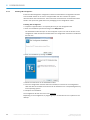
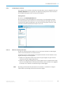
6.3 General notes .....................................................................................................40
6.3.1 Establishing a connection with the configuration PC .......................41
6.3.2 Installing TDC Configurator ................................................................42
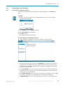
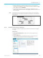
6.4 Connecting to the TDC device ...........................................................................43
6.4.1 Launching the configuration software ...............................................43
6.4.2 Establishing a connection to the TDC device ....................................44
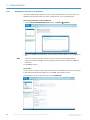
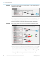
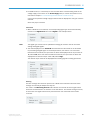
6.5 Adjusting the standard parameters and configuring the interfaces ...............46
6.5.1 General settings ..................................................................................46
6.5.1.1 General ...............................................................................46
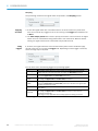
6.5.1.2 GPRS connection data .......................................................48
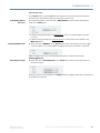
6.5.1.3 Tracking ..............................................................................51
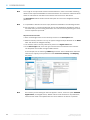
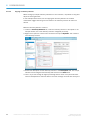
6.5.2 Configuring the interfaces ..................................................................53
6.5.2.1 What are telemetry elements? ..........................................53
6.5.2.2 Configuring a telemetry element for a digital signal ........55
6.5.2.3 Copying a telemetry element.............................................60
6.5.2.4 Configuring a telemetry element for a motor signal ........61
6.5.2.5 Configuring a telemetry element for a fuel level sensor ..62
6.5.3 Configuring the internal sensors ........................................................63
6.5.4 Transferring the configuration to the TDC device .............................64
6.5.5 Saving the configuration on the PC ...................................................64
6.5.6 Recording ............................................................................................64
6.5.7 Displaying system information ...........................................................65
7 Monitoring .......................................................................................................................66
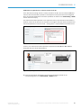
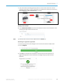
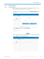
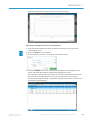
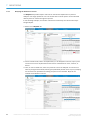
7.1 Setting up a customer account for the SICK online portal ..............................66
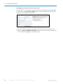
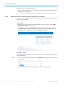
7.1.1 Applying for a customer account .......................................................66
7.1.2 Notification about your customer account ........................................70
7.2 Configuring the TDC Management System.......................................................71
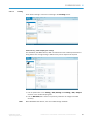
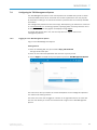
7.2.1 Logging in to the TDC Management System .....................................71
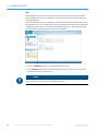
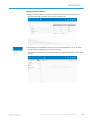
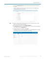
7.2.2 Registering additional TDC devices ...................................................72
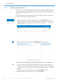
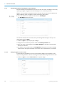
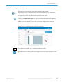
7.2.3 Configuring a dashboard ....................................................................73
7.2.3.1 Creating a dashboard ........................................................73
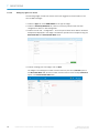
7.2.3.2 Defining the structure for displaying telemetry
elements on the dashboard ..............................................74
7.2.4 Visualizing key figures using widgets on the dashboard ..................76
7.2.4.1 Adding key figures for sensor data ...................................76
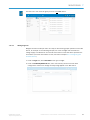
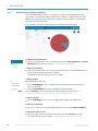
7.2.4.2 Adding key figures for alarms ............................................78
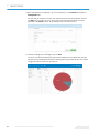
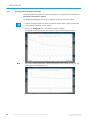
7.2.4.3 Adding diagrams ................................................................79
7.2.5 Analyzing sensor data in detail ..........................................................81
7.2.6 Administering the management platform .........................................82
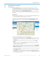
7.3 Working with fleet management .......................................................................83
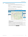
7.3.1 Position display ...................................................................................83
7.3.2 Displaying the vehicle list with detailed information ........................84
7.3.3 Displaying current vehicle fuel levels ................................................84
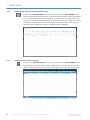
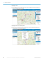
7.3.4 Accessing information about a specific vehicle ................................85
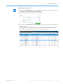
7.3.5 Accessing fuel consumption information ..........................................88
7.3.6 Analyzing the kilometers covered ......................................................90
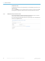
7.4 Transferring data to a customer application using an API interface ..............92
7.4.1 Input parameter ..................................................................................92
7.4.2 Example for API call ............................................................................93
7.5 Accessing data from the TDC device via the MQTT interface ..........................94
7.5.1 Description of the MQTT interface structure .....................................94
7.5.2 Description of the MQTT protocol ......................................................95

ABOUT THESE OPERATING INSTRUCTIONS 1
5
8021804/2017-11-27|SICK
Subject to change without notice
TRANSLATION OF THE ORIGINAL INSTRUCTIONS | Telematic Data Collector
8 Maintenance .................................................................................................................. 97
8.1 Maintenance during operation ......................................................................... 97
8.1.1 Visual inspection ................................................................................ 97
8.1.2 Cleaning .............................................................................................. 98
8.2 Replacing components ................................................................................... 100
8.2.1 Basic procedure ............................................................................... 100
8.2.2 Replacing the GPS antenna ............................................................ 100
8.2.3 Replacing the TDC device overcurrent protection device .............. 101
8.2.4 Replacing the TDC device ................................................................ 102
9 Annex ............................................................................................................................ 103
9.1 Technical data ................................................................................................. 103
9.1.1 TDC-B100 data sheet ...................................................................... 103
9.1.2 TDC-B200 data sheet ...................................................................... 105
9.1.3 TDC-M100 data sheet ..................................................................... 108
9.2 Dimensional drawings ..................................................................................... 110
9.2.1 TDC-B100 dimensional drawing...................................................... 110
9.2.2 TDC-B200 dimensional drawing...................................................... 110
9.2.3 TDC-M100 dimensional drawing ..................................................... 110
10 Figures and tables ....................................................................................................... 111
10.1 List of tables .................................................................................................... 111
10.2 List of figures ................................................................................................... 112

1 ABOUT THESE OPERATING INSTRUCTIONS
6
8021804/2017-11-27|SICK
TRANSLATION OF THE ORIGINAL INSTRUCTIONS | Telematic Data Collector
Subject to change without notice
1 About these operating instructions
Please read this chapter carefully before you begin working with this documentation and
the Telematic Data Collector (TDC for short) gateway system.
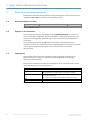
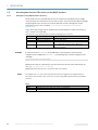
1.1 Described software versions
Software
Function
Status
TDC Configurator
Configuring the TDC devices
≥ V 1.0-0-0
Tab. 1: Software versions
1.2 Purpose of this document
These operating instructions are designed to give technical personnel instructions on
the safe mounting, configuration, electrical installation, commissioning, operation, and
maintenance of the gateway system as well as on the connection and configuration of
the sensors.
These operating instructions do not provide information on operating vehicles or
machines into which the individual devices of the gateway system have been or are going
to be integrated. Additional information on this can be found in the customer
documentation.
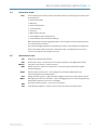
1.3 Target group
These operating instructions are intended for people integrating the devices of the
gateway system into a vehicle or machine and performing initial commissioning,
operation, and maintenance.
They are also intended for the planners and integrators of the customer system, as well
as the operating entity with responsibility for it.
Target group
Tasks
Entity operating the customer system
System user
Operating the system:
The system user reports faults to the system manager.
System manager
Mounting, electrical installation, maintenance, and replacement
of system components:
The system manager submits support requests to SICK.
SICK
SICK service technician
Commissioning, configuration, and support.
Tab. 2: Target group

ABOUT THESE OPERATING INSTRUCTIONS 1
7
8021804/2017-11-27|SICK
Subject to change without notice
TRANSLATION OF THE ORIGINAL INSTRUCTIONS | Telematic Data Collector
1.4 Information depth
These operating instructions contain information about the following topics related to the
profiling system:
• System description
• Mounting
• Electrical installation
• Commissioning
• Operation
• Maintenance and care
• Fault diagnosis and troubleshooting
• Technical data and dimensional drawings
When planning and using the gateway system, technical skills are also required that are
not covered by this document.
The official and legal regulations for operating the system must always be complied with.
Further information about the device components used in the gateway system can be
found in the respective operating instructions.
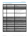
1.5 Abbreviations used
Application programming interface
Access point name = access point of the network operator in the GPRS data network
Controller area network = serial bus system
Global system for mobile communications = technical wireless standard for digital
wireless telephony
General packet radio service = the name given to the packet-based service for
transmitting data within GSM networks
Global positioning system = global satellite navigation system for position determination
Message queue telemetry transport = open messaging protocol for transmitting telemetry
data between devices in the form of messages
Subscriber identity module = chip card for cell phones
Telematic Data Collector = system used to collect and transmit telemetry data
Note
API
APN
CAN bus
GSM
GPRS
GPS
MQTT
SIM
TDC

1 ABOUT THESE OPERATING INSTRUCTIONS
8
8021804/2017-11-27|SICK
TRANSLATION OF THE ORIGINAL INSTRUCTIONS | Telematic Data Collector
Subject to change without notice
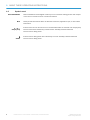
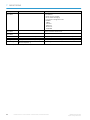
1.6 Symbols used
Recommendations are designed to assist you in the decision-making process with respect
to the use of a certain function or technical measure.
Notes provide information about the features of a device, application tips, or other useful
information.
Instructions that must be carried out in the described order are referred to as step-by-step
instructions and are indicated by numbered lists. Carefully read and follow the
instructions for taking action.
Instructions for taking action are indicated by an arrow. Carefully read and follow the
instructions for taking action.
Recommendation
Note
1. / 2. ...
Step by step
Action

SAFETY 2
9
8021804/2017-11-27|SICK
Subject to change without notice
TRANSLATION OF THE ORIGINAL INSTRUCTIONS | Telematic Data Collector
2 Safety
This chapter concerns your own safety and the safety of the system operator.
▸
Please read this chapter carefully before you begin working with the gateway system.
2.1 Qualified personnel
The gateway system must only be commissioned and maintained by properly qualified
personnel.
A qualified person
• has sufficient skills in the field of the respective equipment based on their technical
training and experience and
• has been instructed by the manufacturer in system operation and all applicable safety
guidelines and
• is familiar with all relevant country-specific occupational safety regulations, work safety
regulations, guidelines, and generally accepted technical rules and standards
(e.g., DIN standards, VDE regulations, country-specific rules) to such an extent that
they are able to evaluate the safe condition of the power-driven machinery, and
• has access to and has read the operating instructions.
2.2 Applications of the system
The Telematic Data Collector (TDC) gateway system is a system used to receive and
transmit telemetry data on a cloud server. It is, for example, ideal for sensor-controlled
monitoring tasks, vehicle tracking, working hours management, and access control as
well as for remote measurement.
The gateway system uses one or more TDC devices to collect data. The TDC devices
feature all of the standard interfaces that are required to integrate sensors and other
devices.
The sensor data received is transmitted to the cloud via the mobile network through either
the SICK online portal or a customer server.
The SICK online portal is a platform that can be used to visualize sensor data on a web-
based user interface, allowing for convenient monitoring.
The TDC gateway system also supports the integration of recorded sensor data into all
leading business applications. Integration is an option when using either the SICK online
portal or a cloud-based customer server via an API included as part of the scope of
delivery or via the MQTT protocol in a defined topic structure.
2.3 Intended use
The gateway system may only be used by qualified personnel in the environment in which
it was mounted and initially commissioned by qualified personnel in accordance with
these operating instructions.
If used in any other way or if alterations are made to the gateway system – including
in the context of mounting and installation – this will render void any warranty claims
directed to SICK AG.
Note

2 SAFETY
10
8021804/2017-11-27|SICK
TRANSLATION OF THE ORIGINAL INSTRUCTIONS | Telematic Data Collector
Subject to change without notice
2.4 General safety notes and protective measures
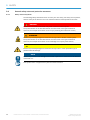
2.4.1 Safety notes and symbols
The following safety and hazard notes concern your own safety, the safety of third parties,
and the safety of the devices. You must therefore observe these symbols at all times.
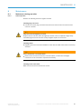
HAZARD
Denotes an immediate hazard that may result in severe to fatal injuries.
The symbol shown on the left-hand side of the note refers to the type of hazard in
question (the example here shows a risk of injury resulting from electrical current).
WARNING
Denotes a potentially dangerous situation that may result in severe to fatal injuries.
The symbol shown on the left-hand side of the note refers to the type of hazard in
question (the example here shows a risk of damage to the eye by laser beams).
WARNING
Denotes a potentially dangerous situation that may result in minor personal injury or
possible material damage.
NOTE
Denotes a potential risk of damage or functional impairment of the device or the devices
connected to it.
This symbol refers to supplementary technical documentation.

SAFETY 2
11
8021804/2017-11-27|SICK
Subject to change without notice
TRANSLATION OF THE ORIGINAL INSTRUCTIONS | Telematic Data Collector
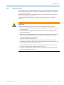
2.4.2 General safety notes
The gateway system has been designed such that it can be operated safely. Protective
devices reduce potential risks to the maximum possible extent. However, a certain level
of risk will always remain.
Awareness of potential sources of danger in the system will help you to work in a safer
manner and thus prevent accidents.
To avoid risks, please also observe the special warnings in each of the individual
chapters.
WARNING
Safety notes
Observe the following to ensure the safe use of the gateway system as intended.
• The notes in these operating instructions (e.g., regarding use, mounting, or installation)
must be observed.
• All official and statutory regulations governing the operation of the gateway system
must be complied with.
• National and international legal specifications apply to the installation and use of the
system, to its commissioning, and to recurring technical inspections, in particular:
- Work safety regulations and safety rules
- Any other relevant safety provisions
• All checks must be carried out by qualified personnel or specially authorized and
commissioned personnel, and must be recorded and documented to ensure that they
can be reconstructed and retraced at any time.
• These operating instructions must be made available to the operator of the system
in which the components of the gateway system are used.
• The operator of the gateway system must be instructed by qualified personnel and
must read the operating instructions.

2 SAFETY
12
8021804/2017-11-27|SICK
TRANSLATION OF THE ORIGINAL INSTRUCTIONS | Telematic Data Collector
Subject to change without notice
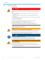
2.4.3 Potential sources of danger
Electrical current
HAZARD
Risk of injury and damage caused by electrical current
Improper handling of live devices may lead to severe personal injury or death by electric
shock.
▸
Electrical installation and maintenance work must only be carried out by personnel
authorized to do so.
▸
The power supply must be disconnected when attaching and detaching electrical
connections.
▸
Select and implement wire cross-sections and their correct fuse protection in accordance
with the applicable standards.
▸
Do not touch any live parts.
▸
In the event of danger, immediately disconnect the device from the grid.
▸
Always use original fuses with the specified current rating.
▸
Report any damaged cables to the maintenance team without delay.
▸
Observe the up-to-date safety regulations when working on electrical systems.
Commissioning/operation/maintenance
WARNING
Risk resulting from incorrect commissioning and configuration
Do not commission until a thorough check has been performed by qualified personnel.
Before carrying out initial commissioning of the devices of the gateway system, you must
have the system checked and approved by qualified personnel.
NOTE
Claims under the warranty rendered void
The housings of the devices must not be opened. The devices are sealed.
If the device is opened, any warranty claims against SICK AG will be void.
WARNING
Risk resulting from faults
Cease operation if the cause of the malfunction has not been clearly identified.
▸
Immediately deactivate the TDC device if you cannot clearly identify the fault and if you
cannot safely remedy the problem.

SAFETY 2
13
8021804/2017-11-27|SICK
Subject to change without notice
TRANSLATION OF THE ORIGINAL INSTRUCTIONS | Telematic Data Collector
2.5 Protecting the environment
The components of the gateway system have been designed to minimize their impact on
the environment. They consume only little energy.
Always act in an environmentally responsible manner at work. For this reason, please note
the following information regarding disposal.
Disposal after final decommissioning
▸
Always dispose of unusable or irreparable devices in accordance with the applicable
waste disposal regulations specific to your country.
▸
Remove the plastic parts and recycle the aluminum housing of the TDC device.
▸
Dispose of all electronic assemblies as hazardous waste. The electronic assemblies are
easy to dismantle.
SICK AG does not take back devices that are unusable or irreparable.
Note

3 SYSTEM DESCRIPTION
14
8021804/2017-11-27|SICK
TRANSLATION OF THE ORIGINAL INSTRUCTIONS | Telematic Data Collector
Subject to change without notice
3 System description
This chapter describes the layout and operating principle of the gateway system, in
particular the interaction of the different components.
Always read this chapter before you mount, install, and commission the components of
the gateway system.
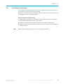
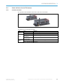
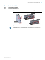
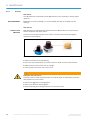
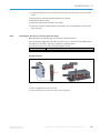
3.1 Scope of delivery
Depending on the installation conditions and number of interfaces required, the gateway
system uses the TDC-B100, TDC-B200 or TDC-M100 device variants. The different TDC
devices are suitable for different installation conditions and numbers of interfaces.
Fig. 1: TDC gateway system device variants
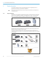
All TDC devices come with a GSM antenna, installed overcurrent protection device, and
SIM card inserted for operation in EU countries.
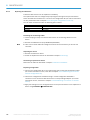
The scope of delivery for TDC devices in the B series also includes a GPS antenna, a
voltage supply cable, and cables for connecting sensors. Additional cables can be ordered
as accessories.
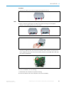
Fig. 2: TDC gateway system scope of delivery
Note

SYSTEM DESCRIPTION 3
15
8021804/2017-11-27|SICK
Subject to change without notice
TRANSLATION OF THE ORIGINAL INSTRUCTIONS | Telematic Data Collector
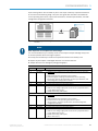
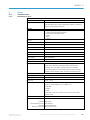
A quick start guide is also included as part of the scope of delivery to provide assistance
at the initial commissioning stage. The quick start guide also includes a download link
for the operating instructions, system documentation, interface specifications, and TDC
Configurator configuration software.
Fig. 3: Quick start guide including download link for the documentation and configuration
software
NOTE
Basic inspection for completeness and damage
It is recommended that you carefully check for and report transport damage of any kind
as soon as possible after receiving the system.
Also verify that the delivery includes all components listed on the delivery note.
▸
Report any incomplete or damaged deliveries to Customer Service.
▸
Always document the damage by taking photographs.
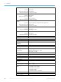
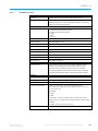
Number
Part No.
Description
1 TDC gateway system consisting of:
n
6064656
TDC-B100 with GSM antenna and installed overcurrent protection
device
SIM card inserted for operation in EU countries
Quick start guide including a download link for the operating
instructions, system documentation, interface specifications, and
TDC Configurator configuration software
n
6067023
GPS antenna
n
6067024
3-A back-up overcurrent protection device
n
6067018
1 cable set consisting of:
Cable for the voltage supply and connection of a peripheral device
to two digital inputs (6-pin)
RS485 connecting cable (4-pin)
and/or
n
6064657
TDC-B200 with GSM antenna and installed overcurrent protection
device
SIM card inserted for operation in EU countries
Download link for the operating instructions, system
documentation, interface specifications, and TDC Configurator
configuration software
n
6067023
GPS antenna
n
6067024
3-A back-up overcurrent protection device
n
6067019
1 cable set consisting of:
Cable for the voltage supply and connection of a peripheral device
to two digital inputs (6-pin)
RS485 connecting cable (4-pin)
INPUT cable (6-pin)

3 SYSTEM DESCRIPTION
16
8021804/2017-11-27|SICK
TRANSLATION OF THE ORIGINAL INSTRUCTIONS | Telematic Data Collector
Subject to change without notice
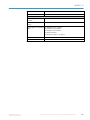
Number
Part No.
Description
and/or
n
6065413
TDC-M100 with GSM antenna and installed overcurrent protection
device
SIM card inserted for operation in EU countries
Quick start guide including a download link for the operating
instructions, system documentation, interface specifications, and
TDC Configurator configuration software
n
6067024
3-A back-up overcurrent protection device
Tab. 3: TDC gateway system scope of delivery
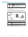
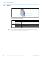
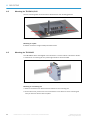
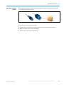
Configuration cables (optional)
There is an optional configuration cable available for all device types that can be used to
connect the TDC device to a configuration PC. The label on the packaging also includes
the link with the access data for the documentation and configuration software.
Fig. 4: Configuration cables (optional)
Part No.
Description
TDC-B100 / TDC-B200
6066259
Cable for connecting the TDC-B100 to a configuration PC, Micro-Fit USB
(6-pin)
Drivers are included in the configuration software
TDC-M100
6066258
Cable for connecting the TDC-M100 to a configuration PC, Micro-Fit USB
Drivers are included in the configuration software
Tab. 4: Configuration cables (optional) – part numbers

SYSTEM DESCRIPTION 3
17
8021804/2017-11-27|SICK
Subject to change without notice
TRANSLATION OF THE ORIGINAL INSTRUCTIONS | Telematic Data Collector
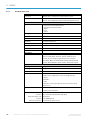
Additional cables (optional)
Preconfigured cables can be obtained for connecting sensors and devices to TDC devices
in the B series.
Part No.
Description
TDC-B100
6067018
1 cable set consisting of:
TDC PWR+2IN – 90 cm, Micro-Fit 4-pin, open ends
TDC RS485 – 30 cm, Micro-Fit 4-pin, open ends
(included in delivery)
6067022
1 cable set with 3 cables (UART/USB, CAN1, DIAG)
TDC-B200
1 cable set consisting of:
TDC PWR+2IN – 90 cm, Micro-Fit 4-pin, open ends
TDC RS485 – 30 cm, Micro-Fit 4-pin, open ends
TDC INPUTS – 30 cm, Micro-Fit 6-pin, open ends
(included in delivery)
6066260
1 cable set with 9 cables (UART, CAN1, DIAG, RS-232, OUTPUTS,
1Wire, USB, CAN2, FULL RS-232)
Tab. 5: Additional connecting cables (optional) – part numbers
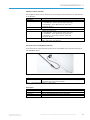
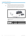
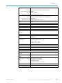
Fuel level sensor for TDC-B200 (optional)
A fuel level sensor manufactured by Omnicomm is available as an optional accessory for
the TDC-B200 device.
Fig. 5: Fuel level sensor (optional)
Part No.
Description
6066264
LLS30160-700mm-RS232/485 fuel level sensor with mounting kits,
connecting cable, and quick start guide.
Tab. 6: Fuel level sensor (optional) – part number
Spare parts
Part No.
Description
5337537
SIM card (for operation in EU countries)
6067024
MINI ATO overcurrent protection device, 32 V, 3 A, 0297003. L
5337536
EAD PST2100SMA RA GSM antenna, penta band
6067023
GPS antenna (only TDC-B100/TDC-B200)
Tab. 7: Spare parts – part numbers

3 SYSTEM DESCRIPTION
18
8021804/2017-11-27|SICK
TRANSLATION OF THE ORIGINAL INSTRUCTIONS | Telematic Data Collector
Subject to change without notice
3.2 System components
3.2.1 TDC devices – collecting and transmitting sensor data
The gateway system uses TDC devices to receive and transmit sensor data.
• As a receiver, the TDC device collects data from connected sensors and devices.
• As a sender, the TDC device transmits the sensor data received to the cloud via the
mobile network.
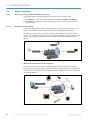
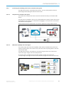
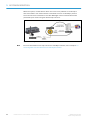
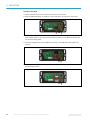
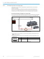
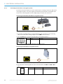
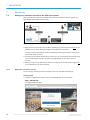
3.2.1.1 The TDC device as a receiver
A TDC device will generally receive sensor data from a vehicle or a machine. For this to
happen, the sensors are connected to the TDC device via appropriate interfaces.
The TDC device also has built-in sensors that are used to detect the movement of the
vehicle. This movement data can be output along with GPS data (this only applies to TDC
devices of the B series). A GPS antenna is included in the scope of delivery for these
devices.
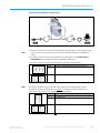
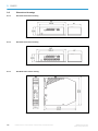
Fig. 6: The TDC device as a sensor data receiver
Which sensors and devices can be integrated?
The TDC device features all of the standard interfaces that are required to integrate
sensors and other devices. Digital, analog, and CAN bus-based signals can be processed.
The interfaces are configured via the TDC Configurator configuration software included in
the scope of delivery.
Fig. 7: TDC device interfaces for the integration of sensors

SYSTEM DESCRIPTION 3
19
8021804/2017-11-27|SICK
Subject to change without notice
TRANSLATION OF THE ORIGINAL INSTRUCTIONS | Telematic Data Collector
• SICK sensors of the TiM series detect the presence of an object within a specified area
(detection). They are ideally suited for monitoring the area around a vehicle, for
instance. If an object is detected in the monitored area, the result is output via the
digital output.
• Capacitive level sensors (such as those from the company Omnicomm) are used for
the level measurement of fuels and oils. When using a capacitive measuring method,
an insulated measurement electrode forms an electric capacitor with the medium
surrounding it. As the level and in turn the capacitance decreases, the latter is analyzed
by electronics and communicated by an electrical signal.
• Capacitive proximity sensors, such as SICK sensors of the CM series, can detect all
kinds of materials beyond a surface. This allows a minimum level to be detected, for
example.
• A TDC device can also process signals from other devices or motors. Vehicle activities
can be traced upon connection to the ignition system.
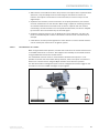
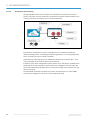
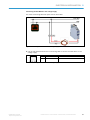
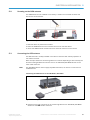
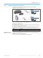
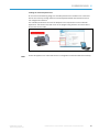
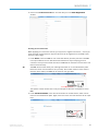
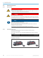
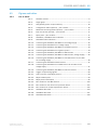
3.2.1.2 The TDC device as a sender
When using the SICK online platform, the TDC device transmits the sensor data received
to the SICK cloud server in real time. This happens automatically via the mobile network
using the SIM card inserted into the TDC device.
If a cloud-based customer server is used instead of the SICK online portal, it is not
possible to transmit the sensor data directly. However, there is the option to access the
data on the customer server using the MQTT interface of the device in question.
The TDC device alarm management system can be configured and used to trigger a real-
time alarm in the form of SMS messages via input signals.
Fig. 8: The TDC device as a sensor data sender

3 SYSTEM DESCRIPTION
20
8021804/2017-11-27|SICK
TRANSLATION OF THE ORIGINAL INSTRUCTIONS | Telematic Data Collector
Subject to change without notice
Permanent data transmission in online mode
The TDC device is connected to a voltage supply and permanently supplied with voltage.
It is also always connected to the mobile network via the SIM card. The GPRS access data
for the SICK online portal is shared with the device through the TDC Configurator
configuration software.
This means that the TDC device is always online, regardless of whether the vehicle or
machine into which the TDC is installed has been started up or not. Sensor data is
therefore always transmitted in real time – even when the motor is not running. Given an
appropriate connection to the TDC device, starting up a motor or machine would therefore
constitute a signal in itself, which could then be transmitted and analyzed.
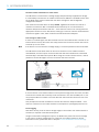
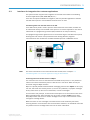
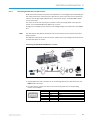
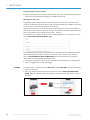
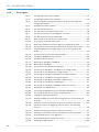
Data storage in offline mode
If there is no mobile signal, the data received from the connected sensors is stored on the
internal device memory. No matter how many sensors are connected, sensor data can be
stored for up to one month.
If the device is not connected to a voltage supply, it will not be possible to save sensor data.
The TDC device will be back online as soon as a connection to the mobile network is
reestablished, and at this point the sensor data that has been saved will be transmitted
automatically to the SICK online portal. When using an internal customer server, it will be
possible to access data again once the connection has been restored.
Fig. 9: Data storage on the TDC device in offline mode
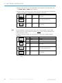
If the connection to the mobile network is interrupted for longer than one month, the data
stored on the internal device memory will be overwritten in line with the FIFO (first in, first
out) principle. What this means is that the data that was stored first will be the first to be
overwritten.
This principle ensures that the data from the last four weeks is always available – even
when the connection to the mobile network is interrupted for a prolonged period of time.
Device logging
TDC device activity, such as when a voltage supply is connected or the mobile network is
accessed, is reported to the SICK online portal.
Using the notification management system, the SICK online portal can issue a message
in the event of a mains voltage failure or a failure of the mobile network (for further
information on this, please also refer to Chapter 3.2.2.3 Visualization and monitoring).
Note
Page is loading ...
Page is loading ...
Page is loading ...
Page is loading ...
Page is loading ...
Page is loading ...
Page is loading ...
Page is loading ...
Page is loading ...
Page is loading ...
Page is loading ...
Page is loading ...
Page is loading ...
Page is loading ...
Page is loading ...
Page is loading ...
Page is loading ...
Page is loading ...
Page is loading ...
Page is loading ...
Page is loading ...
Page is loading ...
Page is loading ...
Page is loading ...
Page is loading ...
Page is loading ...
Page is loading ...
Page is loading ...
Page is loading ...
Page is loading ...
Page is loading ...
Page is loading ...
Page is loading ...
Page is loading ...
Page is loading ...
Page is loading ...
Page is loading ...
Page is loading ...
Page is loading ...
Page is loading ...
Page is loading ...
Page is loading ...
Page is loading ...
Page is loading ...
Page is loading ...
Page is loading ...
Page is loading ...
Page is loading ...
Page is loading ...
Page is loading ...
Page is loading ...
Page is loading ...
Page is loading ...
Page is loading ...
Page is loading ...
Page is loading ...
Page is loading ...
Page is loading ...
Page is loading ...
Page is loading ...
Page is loading ...
Page is loading ...
Page is loading ...
Page is loading ...
Page is loading ...
Page is loading ...
Page is loading ...
Page is loading ...
Page is loading ...
Page is loading ...
Page is loading ...
Page is loading ...
Page is loading ...
Page is loading ...
Page is loading ...
Page is loading ...
Page is loading ...
Page is loading ...
Page is loading ...
Page is loading ...
Page is loading ...
Page is loading ...
Page is loading ...
Page is loading ...
Page is loading ...
Page is loading ...
Page is loading ...
Page is loading ...
Page is loading ...
Page is loading ...
Page is loading ...
Page is loading ...
Page is loading ...
Page is loading ...
Page is loading ...
Page is loading ...
-
 1
1
-
 2
2
-
 3
3
-
 4
4
-
 5
5
-
 6
6
-
 7
7
-
 8
8
-
 9
9
-
 10
10
-
 11
11
-
 12
12
-
 13
13
-
 14
14
-
 15
15
-
 16
16
-
 17
17
-
 18
18
-
 19
19
-
 20
20
-
 21
21
-
 22
22
-
 23
23
-
 24
24
-
 25
25
-
 26
26
-
 27
27
-
 28
28
-
 29
29
-
 30
30
-
 31
31
-
 32
32
-
 33
33
-
 34
34
-
 35
35
-
 36
36
-
 37
37
-
 38
38
-
 39
39
-
 40
40
-
 41
41
-
 42
42
-
 43
43
-
 44
44
-
 45
45
-
 46
46
-
 47
47
-
 48
48
-
 49
49
-
 50
50
-
 51
51
-
 52
52
-
 53
53
-
 54
54
-
 55
55
-
 56
56
-
 57
57
-
 58
58
-
 59
59
-
 60
60
-
 61
61
-
 62
62
-
 63
63
-
 64
64
-
 65
65
-
 66
66
-
 67
67
-
 68
68
-
 69
69
-
 70
70
-
 71
71
-
 72
72
-
 73
73
-
 74
74
-
 75
75
-
 76
76
-
 77
77
-
 78
78
-
 79
79
-
 80
80
-
 81
81
-
 82
82
-
 83
83
-
 84
84
-
 85
85
-
 86
86
-
 87
87
-
 88
88
-
 89
89
-
 90
90
-
 91
91
-
 92
92
-
 93
93
-
 94
94
-
 95
95
-
 96
96
-
 97
97
-
 98
98
-
 99
99
-
 100
100
-
 101
101
-
 102
102
-
 103
103
-
 104
104
-
 105
105
-
 106
106
-
 107
107
-
 108
108
-
 109
109
-
 110
110
-
 111
111
-
 112
112
-
 113
113
-
 114
114
-
 115
115
-
 116
116


SICK TDC Operating instructions
- Category
- Motor vehicle electronics
- Type
- Operating instructions
Ask a question and I''ll find the answer in the document
Finding information in a document is now easier with AI
Related papers
-
SICK TDC-E (TELEMATIC DATA COLLECTOR) Operating instructions
-
-
-
-
-
-
-
-
-
Other documents
-
Siemens MQTT Industrial Edge Connector Connector HurBtor V1.5 User manual
-
Johnson Controls MAP Series Installation Instructions Manual
-
KWorld M100 FAQ
-
Danfoss WS103 User guide
-
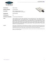 Origin Storage TOS-80/5-NB30 Datasheet
-
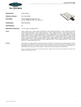 Origin Storage TOS-120/5-NB30 Datasheet
-
Renkforce GSM Alarm System Owner's manual
-
-
Ampire FLEET300 Owner's manual
-
 STRIDE MQTT User manual


